Version 2.0NS022219 6
65
* solid state relay output type factory is set to ,
the relay contact output type factory set to .
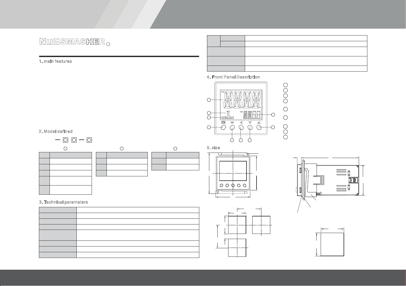
8. default settings.
Control
mode
onoF: on-off control. For situation not requiring high precision.
FPId: advanced artificial intelligence ”FUZZY PID“ control.
onoF
FPId
onr: Reverse acting. Increase in measured variable causes a
decrease in the output, such as heating control.
ond: Direct acting. Increase in measured variable causes an
increase in the output, such as refrigerating control.
Selection of
heating
refrigeration
CntL
orEv onr
ond
Proportional
band
1~32000
Proportional band in PID and APID control. Instead of percentage
of the measurement range, the unit is the same as PV.
Generally, optimal P, I, D and CP can obtained by auto tuning. They
can also be manually inputted if you already know the correct
values.
P
CP Control cycle CP reflect the instrument operator to adjust the speed, the size of
the CP that affect the control accuracy.
With SSR, SCR output control cycle preferable to shorter, usually
0.5-3.0 Seconds. The relay switch output is generally in 15-40 sec.
When the output relay switches , the CP will be limited to
3 seconds, And self-tuning At will automatically set the CP as the
appropriate value, taking into account the control accuracy And
mechanical switch life.
When the control mode CntL = onoF, the action of the CP as an
output disconnect or power-on output ON Delay time.
0.2~
300.0
Int Input Signal Input spec:
K、E、J、N、Pt(Pt100)
dp Decimal
point
0 (no decimal), 0.0 (one decimal place).
InF
dU
SvL
SvH
-999~
+3200
SC Input Shift
Adjustment
Sc is used to shift input to compensate the error caused by
transducer, input signal, or auto cold junction compensation of
thermocouple.
PV after compensation=PV before compensation + Sc It is generally
set to 0. The incorrect setting will cause measurement inaccurate.
-199.9~
+400.0
PV
input filter
The value of InF will determine the ability of filtering noise.
When a large value is set, the measurement input is stabilized but
the response speed is slow. Generally, it can be set to 1 to 3.
If great interference exists, then you can increase parameter “InF”
gradually to make momentary fluctuation of measured value less
than 2 to 5.
When the instrument is being metrological verified, “InF” s can be
set to 0 or 1 to shorten the response time.
Temperature
unit selection
°C:
°F:fahenheit equals
celsius equals
Low limit
of SV
Minimum value that SV is allowed to be.
Upper limit
of SV
Maximum value that SV is allowed to be.
0~40
°C
°F
HYS Control
hysteresis
0~200.0
HYS is used for on-off control to avoid frequent on-off action of relay.
For a reverse acting (heating) system, when PV > SV, output turns
off; when PV<SV-HYS, output turns on.
For a direct acting (cooling) system, when PV<SV, output turns off;
when PV>SV+HYS, output turns on.
Differential
time
No derivative effect when d=0 0~3200
seconds
d
0
0.0
Integration
time
No integral effect when I=0 1~9999
seconds
I
*
Parameter code factory setting Parameter code Parameter code
factory setting factory setting
9. Wiring diagram.
+
ABB
-
1 2
109876
11
12
13
345
AL1
-
+
OUT
COM
N/O
AL2
N/O
N/OCOM N/C
POWE R
COM
10. Note
( )
( )
( )
1 Can not normally display measured values in the display window alternating show:
"orAL" character, indicating that the input of the measurement signal abnormalities or Out of
range; check Int parameter settings, and then the input sensor signals are the same category,
if it is determined the same, check the input sensing Signal not pick the wrong line, if it is
determined to not pick the wrong line, check whether the sensor problem, replace another
sensor to try.
2
heat dissipation, instrument internal temperature rise due to thermal radiation will lead to a
result of the measurement accuracy and service life of the affected. In this Case, to be taken
to a forced cooling fan or other measures to reduce the ambient temperature.
3 the extension or connection then the thermocouple leads should be used with the
thermocouple type to match the compensation conductor; extend or connect the
thermoelectric Resistance of the lead, you should use the minimal resistance of the wire and
cable away from power lines and load connection, in order to avoid signal interference.
The instrument used by the local environmental temperature and humidity can not
exceed the scope of the provisions, the instrument around should allow sufficient space for
R
SMASHER