@)
HITACHI
©
SERVICE
MANUAL
No.
236EGF
HT-60S
CONTENTS
OY
SPECIFICATIONS
1
SERVICE
POINTS
.........2ccsccsessescscescessssaeessenes
Sic
Sunibaamcrld
ciety
ails
wang
Save
Uap
iawnitese
cies
6
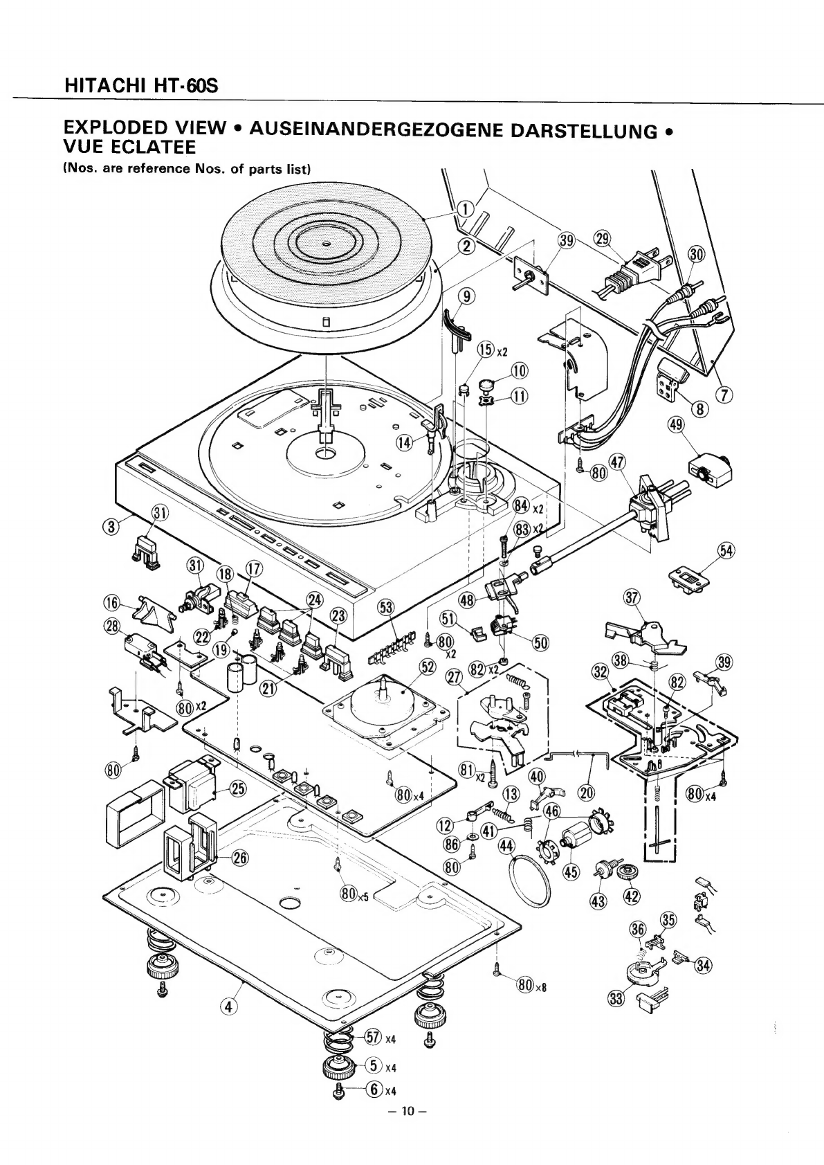
EXPLODED
VIEW
........:ccccccesescessesseeeesvaceneens
10
REPLACEMENT
PARTS
LIST
..........0.:000c0000-
11.145
BLOCK
DIAGRAM
...........cscssescsecsessesesecseeeene
"2
CIRCUIT
DIAGRAM
........cccceccccccesescscseestaeens
13
PRINTED
WIRING
BOARD
.............c000cc0c0000
14
TROUBLESHOOTING
........ccsscssseesescseseeseseens
17
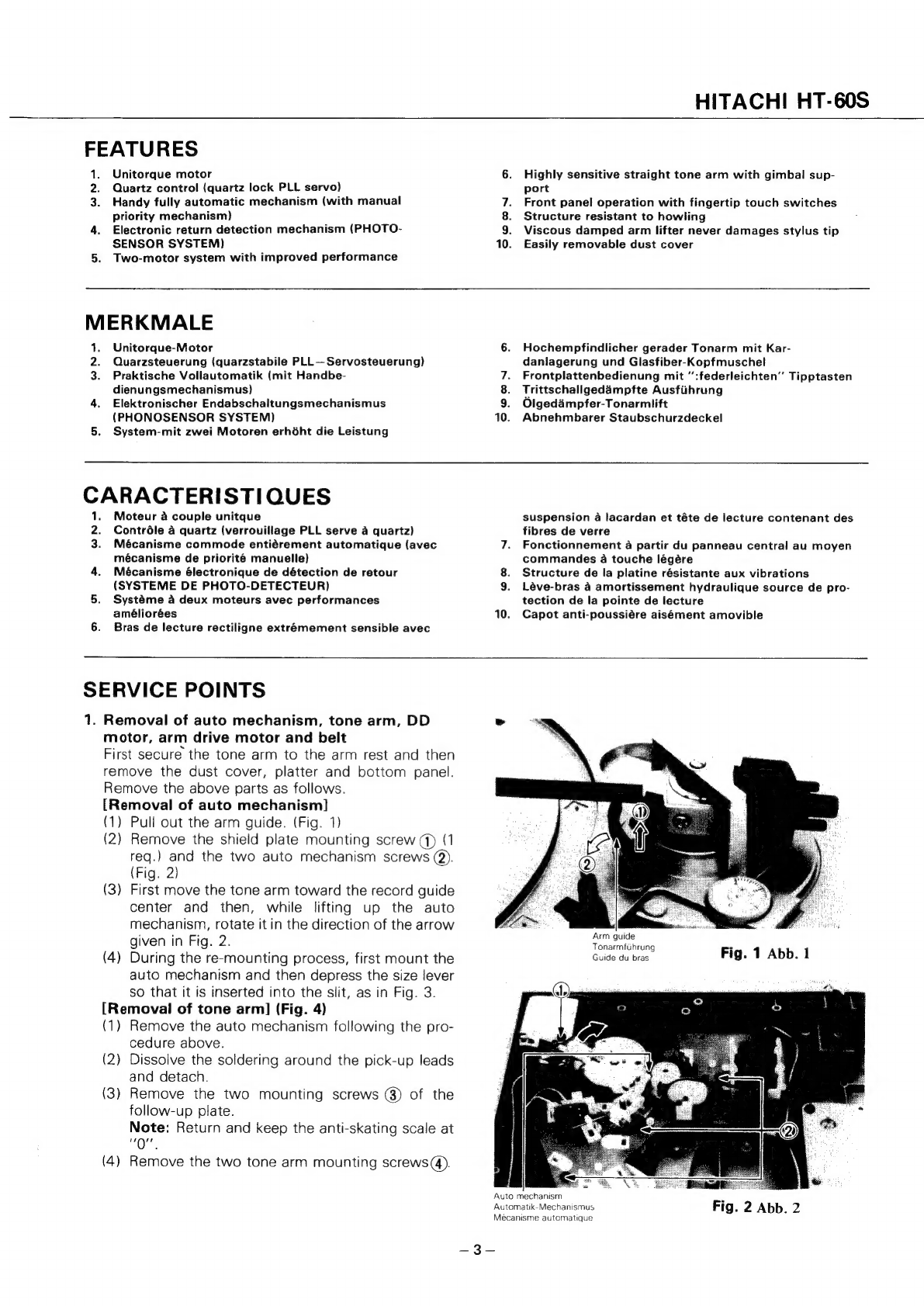
Refer
to
the
HT
—464
Service
Manual
(No.
194)
for
the
operation
of
this
unit's
auto
mechanism
since
it
is
exactly
the
same.
Einzelheiten
Uber
die
Arbeitsweise
der
Automatik
dieses
Gerats
kann
man
dem
Service-Handbuch
fiir
das
Modell
HT
—464
(Nr.
194)
entenehmen,
da
beide
identisch
sind.
En
ce
qui
concerne
le
fonctionnement
du
mécanisme
automatique
de
cet
appareil,
se
reporter
au
Manuel
d’entretien
(N°
194)
du
HT
—464,
car
ils
sont
exactement
identiques.
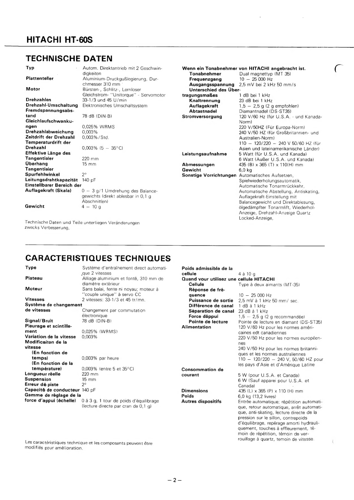
SPECIFICATIONS
Type
2-speed
direct
drive
automatic
system
Platter
Aluminum
alloy
die-cast,
310
mm
outer
diameter
Motor
Brushless,
slotless,
coreless
DC
servo
“Unitorque’”’
motor
Speed
2-speeds;
33-1/3
and
45
rpm
Speed
change
system
Electronic
change-over
system
S/N
78
dB
(DIN-B)
Wow
and
Flutter
0.025%
WRMS
Speed
deviation
0.003%
0.003%
hour
0.003%
(5
—
35°C)
Speed
drift
(for
time)
(for
temperature)
Effective
length
220
mm
Overhang
15
mm
Tracking
error
2°
Lead
wire
capacitance
140
pF
Adfustable
force
range
(scale)
0
—
3/1
turn
of
the
tabalce
weight
{directly
readable
in
0.1
g
steps)
Acceptable
cartridge
weight
4—
10g
When
a
HITACHI
cartridge
is
attached.
Cartridge
Duai
magnet
type
(MT-35)
Frequency
response
10
—
25,000
Hz
2.5
mV
at
1
kHz
500
mm/sec.
1
dB
at
1
kHz
23
dB
at
1
kHz
1.5
—
2.5
g
(recommended
2g)
Diamond
stylus
(DS-ST35)
120
V
60
Hz
for
U.S.A.
and
Canada
standard
220
V
50
Hz
for
Europe
standard
240
V
50
Hz
for
U.K.
and
Australia
standard
110
—
120/220
~
240
V
50/60
Hz
for
Asian
and
Latin
American
countries
5
watts
(for
U.S.A.
and
Canada)
6
watts
(
except
U.S.A.
and
Canada)
435
x
365
x
110
mm
(17-1/8"
x
14-3/8"
x
4-5/16")
6.0
kg
(13.2
Ibs.)
Auto-in,
auto-repeat,
auto-return,
auto-
Cut,
anti-skating,
tracking
force
direct-
reading
balance
weight,
viscous
damped
cueing,
repeat
indicator,
speed
in-
dicator,
quartz
locked
indicator
Output
voltage
Channel
difference
Channel
separation
Tracking
force
Stylus
tip
Power
source
Power
consumption
Dimensions
Weight
Other
devices
Specifications
and
Parts
are
subiect
to
change
for
improvement.
DIRECT
DRIVE
AUTOMATIC
TURNTABLE
October
1980
TOYOKAWA
WORKS