December 2018 4
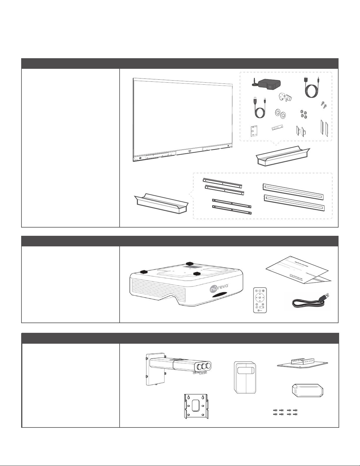
What’s in the box
V
Box 1: Touch panel
Box 3: Wall mount
TWall mount
UWall mount covers
VWall plate
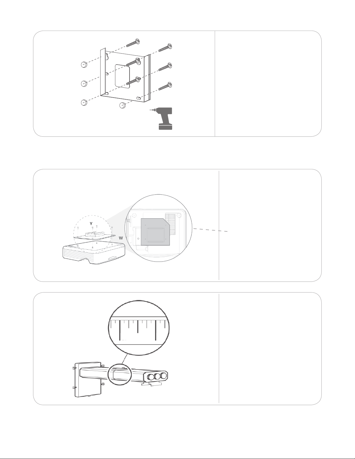
WProjector plate
XMount end-cap
YScrews to attach plate to projector
(x4) and screws to attach projector
to mount (x4).
-- Warranty and warnings documents
ATouch panel
BWall brackets
CWall spacers
DFront covers
EPower supply
FPower adapters (x4)
GRS232 to 3.5mm cable
HUSB A-B cable
I Washers
JBottom end-cap nuts
KTop end-cap screws
LBottom end-caps
MBottom connector plate
NTop connector plate
OTop end-caps
-- Warranty and warnings documents
Box 2: Projector
A
PInteractive projector
QProjector remote control
R Country-specic power cable
SInstallation template
-- Warranty, warnings, Quick start
guide, installation drawing and
outline drawing documents
1
BOX 2 – PROJECTOR
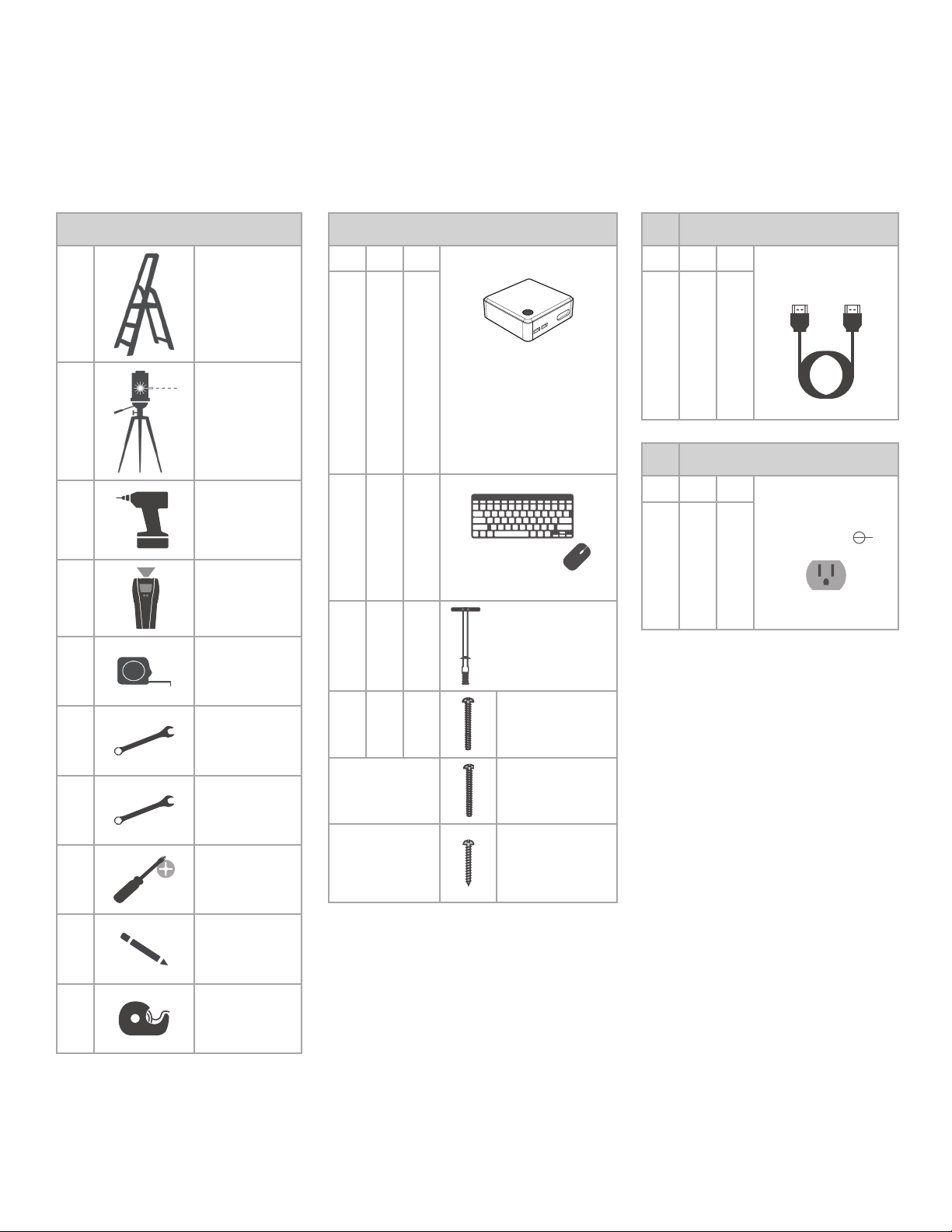
YOU WILL NEED
BOX 1 – TOUCH PANEL
1.2
Z - Toggler™ snaptoggle
Model BB
or
a similar anchor
A - Touch panel
B - Covers
C - Wall brackets
D - Wall spacers
E - Power supply
F - Power adaptors (x4)
G - RS232 to 3.5mm cable
H - USB A-B cable
I - Washers
L - Bottom end caps
M - Bottom connector plate
N - Top connector plate
O - Top end caps
AA - HDMI cable
T - Projector wall
mount
U - Wall mount cover (L/R) V - Wall mount plate
W - Projector plate
X - Adjustment cover Y - Screws to attach plate to
projector and screws to
attach projector to mount
Install according to manufacturer instructions
Installez conformément aux instructions du fabricant
Instalar según las instrucciones del fabricante
Instalaci je nutné provést v souladu s pokyny výrobce
Installer i henhold til producentens instruktioner
Installeren volgens de instructies van de fabrikant
Bitte gemäß den Herstellerangaben montieren
Effettua l'installazione seguendo le istruzioni del
produttore
Installer etter produsentens anvisninger
Установите согласно инструкциям производителя
Installera enligt tillverkarens instruktioner
EN
FR
ES
CS
DA
NL
DE
IT
NO
RU
SV
P - Projector Q - Projector remote control R - Power cable
BOX 3 – WALL MOUNT
K - Top end cap screws
J - Bottom end cap nuts
S - Installation template
Nureva Wall – WM408i
QUICK START GUIDE
© 2018 Nureva Inc. All rights reserved. Nureva and the Nureva logo are trademarks of Nureva Inc. in the United States, Canada and other countries.
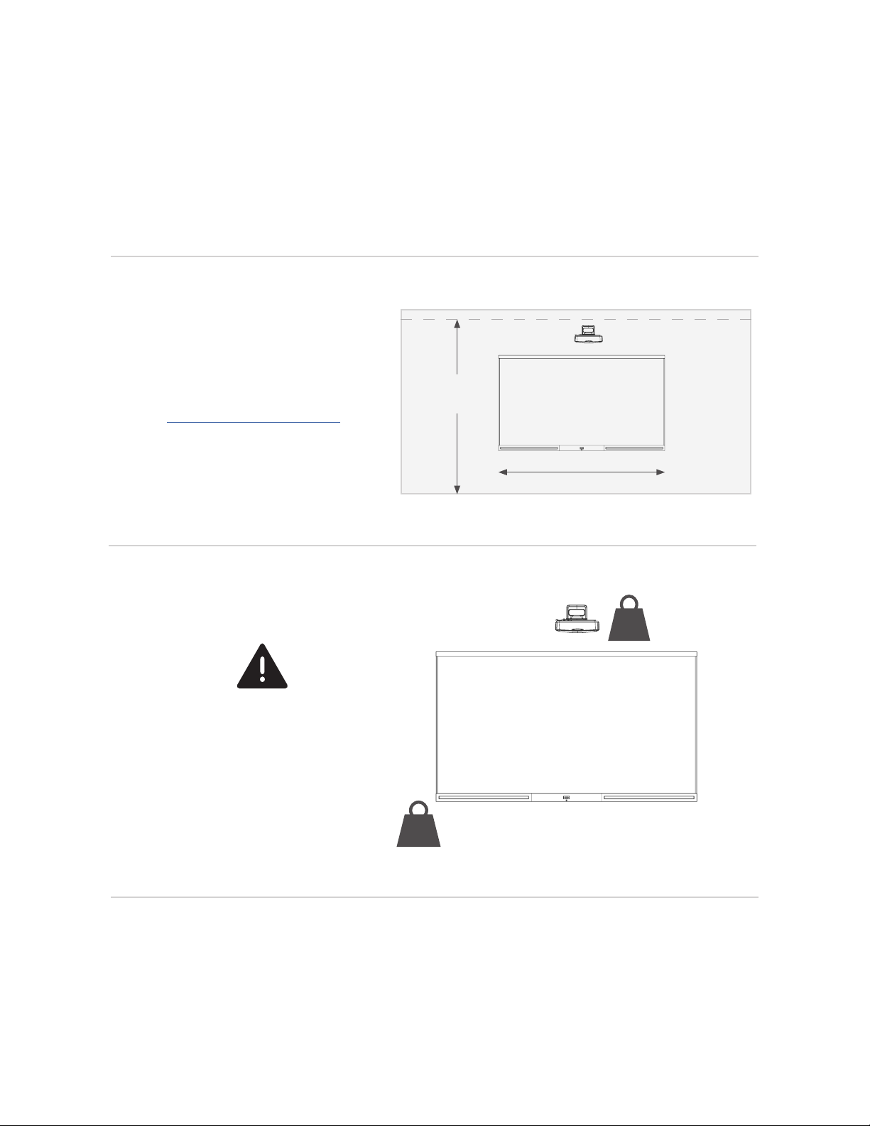
81¼”
(206.4 cm)
SYSTEM / IMAGE CENTER
PROJECTOR MOUNTING PLATE
1
4
3
16
A
B
C
D
2
E
F
M
P
QR
T
UV
WX Y
H
L
I
G
AA
Z
Z
J
K
O
N
8mm
10mm
S
S
44 ½”
(113.5 cm)
Page 1 of 4
101402-02
44 ½”
(113.5 cm)
min 3 ½”
(8.9 cm)
V
Z
1
BOX 2 – PROJECTOR
YOU WILL NEED
BOX 1 – TOUCH PANEL
1.2
Z - Toggler™ snaptoggle
Model BB
or
a similar anchor
A - Touch panel
B - Covers
C - Wall brackets
D - Wall spacers
E - Power supply
F - Power adaptors (x4)
G - RS232 to 3.5mm cable
H - USB A-B cable
I - Washers
L - Bottom end caps
M - Bottom connector plate
N - Top connector plate
O - Top end caps
AA - HDMI cable
T - Projector wall
mount
U - Wall mount cover (L/R) V - Wall mount plate
W - Projector plate
X - Adjustment cover Y - Screws to attach plate to
projector and screws to
attach projector to mount
Install according to manufacturer instructions
Installez conformément aux instructions du fabricant
Instalar según las instrucciones del fabricante
Instalaci je nutné provést v souladu s pokyny výrobce
Installer i henhold til producentens instruktioner
Installeren volgens de instructies van de fabrikant
Bitte gemäß den Herstellerangaben montieren
Effettua l'installazione seguendo le istruzioni del
produttore
Installer etter produsentens anvisninger
Установите согласно инструкциям производителя
Installera enligt tillverkarens instruktioner
EN
FR
ES
CS
DA
NL
DE
IT
NO
RU
SV
P - Projector Q - Projector remote control R - Power cable
BOX 3 – WALL MOUNT
K - Top end cap screws
J - Bottom end cap nuts
S - Installation template
Nureva Wall – WM408i
QUICK START GUIDE
© 2018 Nureva Inc. All rights reserved. Nureva and the Nureva logo are trademarks of Nureva Inc. in the United States, Canada and other countries.
81¼”
(206.4 cm)
SYSTEM / IMAGE CENTER
PROJECTOR MOUNTING PLATE
1
4
3
16
A
B
C
D
2
E
F
M
P
QR
T
UV
WX Y
H
L
I
G
AA
Z
Z
J
K
O
N
8mm
10mm
S
S
44 ½”
(113.5 cm)
Page 1 of 4
101402-02
44 ½”
(113.5 cm)
min 3 ½”
(8.9 cm)
V
Z
B
C
D
P
S
QR
TU
W
X
Y