NUVE EN 032 User manual

NÜVE SANAYİ MALZEMELERİ İMALAT VE TİCARET A.Ş.
EN 032 / EN 055 / EN 120
INCUBATORS
USER’S MANUAL
Z14.K25 096 Rev.No: 04 Rev.Date: 03/2018

2
Dear Nüve User,
We would like to take this opportunity to thank you for preferring this Nüve product. Please
read the operating instructions carefully and keep them handy for future reference.
Please detain the packing material until you see that the unit is in good condition and it is
operating properly. If an external or internal damage is observed, contact the transportation
company immediately and report the damage. According to ICC regulations, this responsibility
belongs to the customer.
While you are operating the instrument please;
1. obey all warning labels,
2. do not remove warning labels,
3. do not operate damaged instrument,
4. do not operate instrument with a damaged cable,
5. do not move instrument during operation.
In case of a problem contact your Nüve agent for an authorized service or maintenance.
The validity of the guarantee is subject to compliance with the instructions and precautions
described in this manual.
Nüve reserves the right to improve or change the design of its products without any obligation
to modify previously manufactured products.
Information contained in this document is the property of Nüve. It may not be duplicated or
distributed without our permission.
NÜVE
SANAYİ MALZEMELERİ
İMALAT VE TİCARET A.Ş.
Saracalar Mahallesi, Saracalar Kümeevleri No:4/2 Akyurt 06750
Ankara / TURKEY
Tel : (90.312) 399 28 30 (pbx)
Fax : (90.312) 399 21 97

3
WARRANTY CERTIFICATE
1. Nüve warrants that the equipment delivered is free from defects in material and
workmanship. This warranty is given for a period of two years. The warranty period begins
from the delivery date.
2. Warranty does not apply to parts normally consumed during operation or general
maintenance or any adjustments described in the operating instructions provided with the
instrument.
3. Nüve does not accept any liability in case where the goods are not used in accordance with
their proper intent.
4. The warranty may not be claimed for damages incurred during the shipment, for damages
resulting from improper handling or use, abuse, fire, liquid spillage, tampering or
unauthorized repairs by any persons, use of defective or incompatible accessories, exposure
to abnormally corrosive conditions, use of the product in non-standard environmental
conditions, including but not limited to failure to meet requirements of ambient
temperature, lubrication, humidity or magnetic field influences, from the defects in
maintenance, negligence, bad functioning of auxiliary equipment, in the case of force
majeure or accident and incorrect power supply.
5. Any injury, loss or damage caused; due to a failure resulting from negligence of the
instructions given in this manual; is beyond the scope of the warranty conditions.
BEFORE OPERATING THE INSTRUMENT THIS MANUAL SHOULD BE READ CAREFULLY.
THE VALIDITY OF THE GUARANTEE IS SUBJECT TO THE OBSERVATION OF THE
INSTRUCTIONS AND PRECAUTIONS DESCRIBED IN THIS MANUAL.
INFORMATION CONTAINED IN THIS DOCUMENT IS THE PROPERTY OF NÜVE. IT MAY
NOT BE DUPLICATED OR DISTRIBUTED WITHOUT PERMISSION.
PLEASE REGISTER ONLINE TO VALIDATE YOUR WARRANTY:
To register your warranty online, please visit our webpage www.nuve.com.tr and fill in the
“Warranty Registration Form”.

4
CONTENT
Page
CONTENT................................................................................................................................................................ 4
1. INTRODUCTION............................................................................................................................................. 5
1.1. USE AND FUNCTION .................................................................................................................................... 5
2. TECHNICAL SPECIFICATIONS.......................................................................................................................... 6
2.1. TECHNICAL SPECIFICATIONS TABLE............................................................................................................. 6
2.2. OPTIONAL ACCESSORIES ............................................................................................................................. 6
3. PRECAUTIONS AND LIMITATIONS ON USE .................................................................................................... 7
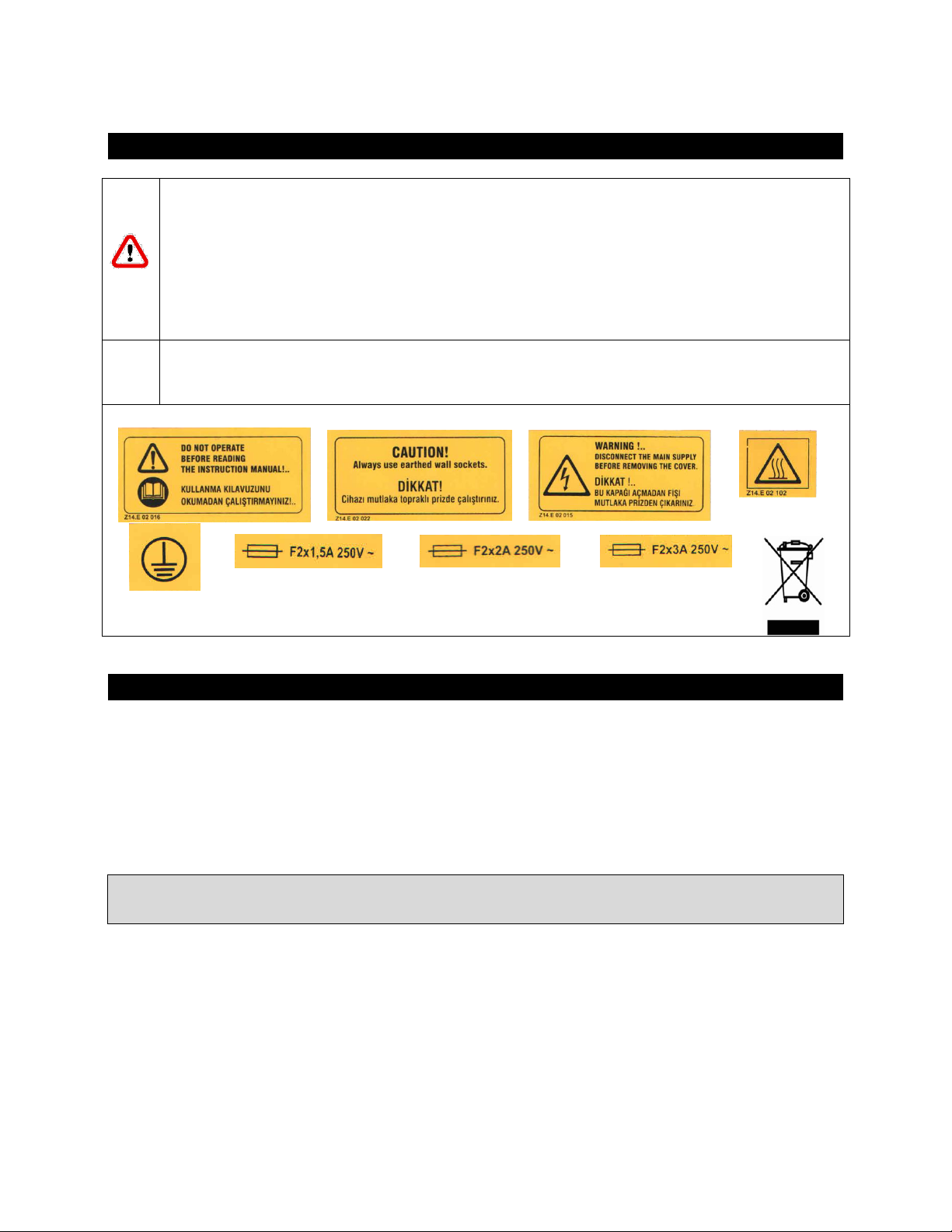
4. SYMBOLS AND LABELS .................................................................................................................................. 8
5. INSTALLATION............................................................................................................................................... 8
5.1. ENVIRONMENTAL CONDITIONS .................................................................................................................. 8
5.2. HANDLING AND TRANSPORTATION ............................................................................................................ 8
5.3. UNPACKING................................................................................................................................................. 9
5.4. MAINS SUPPLY ............................................................................................................................................ 9
5.5. POSITIONING............................................................................................................................................... 9
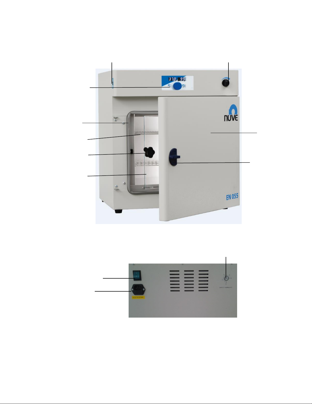
5.6. GENERAL PRESENTATION.......................................................................................................................... 10
5.7. CONTROL PANEL ....................................................................................................................................... 11
5.7.1. Explanations and Functions for Display and Control Panel .................................................................. 11
5.8. PRIOR TO OPERATION ............................................................................................................................... 12
6. OPERATING PRINCIPLES ...............................................................................................................................13
6.1. PREPARATION OF USER SETTINGS............................................................................................................. 13
6.1.1. oP Operator Menu Parameters ............................................................................................................ 13
6.2. PROGRAMMING SUMMARY ..................................................................................................................... 14
6.3. COMPLETION OF THE OPERATION ............................................................................................................ 17
7. PERIODIC MAINTENANCE AND CLEANING....................................................................................................17
7.1. PERIODIC MAINTENANCE.......................................................................................................................... 17
7.2. CLEANING.................................................................................................................................................. 17
8. DISPOSAL MANAGEMENT CONCEPT ............................................................................................................18
9. TROUBLESHOOTING.....................................................................................................................................18
9.1. ERROR CODES EXPLANATIONS .................................................................................................................. 18
9.2. FUSE REPLACEMENT ................................................................................................................................. 19
10. ELECTRICAL CIRCUIT DIAGRAM................................................................................................................20
10.1. EN 032 ELECTRICAL CIRCUIT DIAGRAM ..................................................................................................... 20
10.2. EN 055 AND EN 120 ELECTRICAL CIRCUIT DIAGRAM ................................................................................. 21

5
1. INTRODUCTION
1.1. USE AND FUNCTION
EN 032, EN 055 and EN 120 incubators are designed to provide excellent incubation conditions
for applications in biology and microbiology laboratories such as medical and veterinary fields;
research and quality control examinations in pharmaceutical, food and cosmetics industries and
biotechnology.
EN 032, EN 055 and EN 120 incubators provide temperature range between the ambient
temperature plus 5C and 100C and keeps temperature stable within given tolerances. The
incubators have timer which can be programmed up to 99.9 hours including hold position and
the incubators stop to operate after the set time is completed. Cross contamination risk is
minimized by means of natural air circulation.
Stable and homogeneous temperature in the chamber is provided by means of the natural air
circulation through the stainless steel heaters placed onto the three outer surface of the
chamber.
The insulation proportional to the dimensions of the incubator not only provides a homogenous
temperature distribution but also makes the operation of incubator economics. The incubator
ensures reliable working conditions by N-PrimeTM programmable microprocessor with high
control accuracy. Adjustable safety thermostat offers an additional safety for your operations.
Microprocessor control system will shut down the temperature sensor and in case of
malfunctions that may occur in the control system, alarm system will be activated and the user
is warned visually and audibly. The study data are recorded in the memory and can be
transferred to external USB memory. At the same time, unauthorized persons have been
blocked permission to change parameters with improved password menu.
EN 032N, EN 055N and EN 120N Incubators are manufactured according to the following
standards: EN 61010-1, EN 61010-2-010, EN 50419, EN 61000-6-3, DIN 12880.
This device is in compliance with WEEE Regulation.
If the warnings mentioned in this manual are not considered, NUVE will not be responsible
from their results.

6
2. TECHNICAL SPECIFICATIONS
2.1. TECHNICAL SPECIFICATIONS TABLE
TECHNICAL SPECIFICATIONS
EN 032
EN 055
EN 120
Temperature Range
Ambient Temperature +5°C / 100°C
Temperature Sensor
Pt-100
Temperature Control System
N-PrimeTM
Temperature Set and Display Sensitivity
0.1°C
Temperature Variation (*at 37°C)
<± 0.5°C
Temperature Variation (*at 56°C)
<± 1 °C
Temperature Fluctuation (*at 37°C)
± 0.1°C
Temperature Fluctuation (*at 56°C)
± 0.2°C
Timer
1 minute-99.9 hours / Hold position
Program Delay
1 minute-99.9 hours / Hold position
Safety System
Safety Thermostat (30C–110C)
Useful Volume (liter)
32
55
120
Number of shelves (standard/maximum) pcs.
2/6
2/7
2/10
Power Consumption
300 W
350 W
400 W
Power Supply
230 V, 50/60 Hz.
Memory
3000 data*
Internal Material
Stainless Steel
External Material
Epoxy-polyester powder coated steel
Internal Dimensions (W x D x H) mm
330 x 300 x 335
420 x 370 x 365
500 x 480 x 500
External Dimensions (W x D x H) mm
565 x 500 x 685
645 x 560 x 710
730 x 670 x 850
Packing Dimensions (W x D x H) mm
670x600x920
720 x 650 x 930
800 x 750 x 1070
Net / Packed Weight (kg)
38 / 42
46/49
57/66
*Shows the number of lines for each work done. Temperature, time and if there is error code
consist of 1 line.
2.2. OPTIONAL ACCESSORIES
R 01 133 Mesh type shelf (EN 032N)
R 01 127 Mesh type shelf (EN 055N)
R 01 031 Mesh type shelf (EN 120N)
K 23 049 Shelf carrier (EN 032N)
K 23 048 Shelf carrier (EN 055N)
K 23 040 Shelf carrier (EN 120N)
Two pieces shelf carriers should be ordered for each shelf.

7
3. PRECAUTIONS AND LIMITATIONS ON USE
The user shall pay attention to the following:
•Do not operate the instrument for purposes other than its main purpose.
•The instrument should only be used by authorized and trained staff after the instruction
manual has been read carefully. Only authorized technical staff can handle the product in
case of a failure.
•Only original spare parts and original accessories supplied by Nüve should be used.
•Correctly grounded power supply should be used.
•The set temperature should not destroy the structure of the samples without user’s notice.
•The boiling points of the samples should be higher than the set temperature.
•The freezing points of the samples are lower than the set the temperature.
•The samples which may liquefy and expand should not be in a sealed container.
•Liquids which may expand during heating should not overflow from their containers.
•In necessary cases, the ventilation hole should be opened to discharge the gases and the
vapors produced during heating.
•The safety thermostat should be adjusted to the temperature higher than the set
temperature.
•There should not be any material in the chamber that can damage to the incubator.
•The materials which will be subject to heating or drying should not be combustible,
explosive, heat susceptible, flammable, adhesive and fusible.
•Ensure that the vapors and gases generated during the operation are not harmful to human
health and flammable or explosive.

8
4. SYMBOLS AND LABELS
Symbol in the operating instructions:
Attention, general hazard area.
This symbol refers to safety relevant warnings and indicates possibly dangerous
situations. The non-adherence to these warnings can lead to material damage and injury
to personal.
Symbol in the operating instructions:
This symbol refers to important circumstances.
Labels on the products:
Hot Surface
EN 032N Fuses
EN 055N Fuses
EN 120N Fuses
Topraklı Priz
(2x1,5 A)
(2 x 2 A)
(2 x 3 A)
5. INSTALLATION
5.1. ENVIRONMENTAL CONDITIONS
The instrument is design to operate safely under the following conditions:
•Indoor use only
•Ambient temperature: 5°C to 40°C
•Maximum relative humidity for temperature up to 31°C: 80%
•Maximum altitude: 2000 m
•Temperature for maximum performance: 15°C / 25°C
The instrument is designed to operate in 20°C (±5°C) laboratory conditions. The
efficiency of the unit may decrease if the ambient temperature exceeds the limits.
5.2. HANDLING AND TRANSPORTATION
All handling and transportation must be carried out by using proper equipment and experienced
staff. The instrument must be supported underneath and never be turned upside down.

9
5.3. UNPACKING
Remove the cardboard box packing and the second nylon wrapping around the instrument.
Ensure that no damage has occurred during transportation. The below mentioned are provided
with the instrument, please check them;
•1 ea. user’s manual and warranty
•1 ea. power cord
•2 ea. shelves
•4 ea. shelf carriers
5.4. MAINS SUPPLY
The instrument requires 230V, 50/60 Hz. Please make sure that the supplied mains matches the
required power ratings which are written on the name of plate of the instrument located at the
back of the incubator.
Always plug-in the instrument to correctly grounded sockets.
A supply fitted with a circuit breaker should be used for protection against indirect
contact in case of isolation fault.
5.5. POSITIONING
•Check that the positioning is suitable for the users.
•Check that the instrument is stable on its four feet. If necessary, provide stable standing by
adjusting the pedestal heights.
•Check that the user is able to follow the operation even when he deals with something else.
•Check that the positioning of the device prevents interference with other equipment in the
near surrounding.
•The bench where the instrument is positioned should be resistant to the weight of the
instrument and vibration free.
•Leave at least 20 cm free space between the equipment and wall.

10
5.6. GENERAL PRESENTATION
Figure 1
Figure 2
Ventilation Adjustment Button
Display and
Control Panel
Door Handle
POWER SWITCH
FUSE HOLDER AND
SUPPLY INLET
SAFETY THERMOSTAT
Shelf
Gasket
Glass Door Handle
Glass Door
Door
Input USB

11
5.7. CONTROL PANEL
1. Temperature display
6. “Operating the program” lamp
11. Back / Alarm mute button
2. Time display
7. Data transfer lamp
3. Encoder button
8. Alarm led
4. Start / Stop button
9. “End of the program” lamp
5. Heating lamp
10. Usb lamp
5.7.1. Explanations and Functions for Display and Control Panel
01-Temperature Display
This display shows
Sterilization chamber temperature during “stand-by” and during the operation (thermometer
position),
During program preparation, the temperature setting values or the alarm setting values,
Failure codes,
EoF warning when power is interrupted,
The set temperature values and alarm values.
02-Time Display
This display shows the values set for time during program preparation. Also; this display shows
he time values in the control of the settings.
03-Encoder Button

12
The encoder button has two physical movements. The button turn clockwise and anticlockwise
to increase or decrease the temperature and time values of the program. Also, the button press
for select / confirm.
04-Start / Stop Button
Used button to start the device to operating at set values or to stop the operation.
05-Heating Lamp
The led is “on” during heating, it indicates that the heating process is carried out.
06-“Operating The Program” Lamp
A lamp indicating that the program is running as soon as the device is started.
07-Data Transfer Lamp
The lamp indicates that the records are transferred in the memory or the file is transferred
during software update.
08-Alarm Led
This led flashes when there is a warning or error on the device.
09-“End of The Program” Lamp
It is a warning lamp that indicates that the running program is finished.
10-Usb Lamp
This lamp is on when connected to a USB external memory.
The device supports up to 8 GB of external memory.
11-Back / Alarm Mute Button
This button is used to silence audible alarms in case of error and cancel the changes in the
menu.
5.8. PRIOR TO OPERATION
•Plug-in the instrument to correctly grounded sockets.
•Push the power switch. See that the power lamp is turn on.
•See that the microprocessor control system is activated.
•Learn the function of the control panel (See 5.7).
•Set the temperature value according to your need (See Section 6.2).

13
6. OPERATING PRINCIPLES
6.1. PREPARATION OF USER SETTINGS
The device has a password protected menu. The password is set to “000” when the device first
starts. Follow the below steps to change the password, update current date / time information
and access the operator's menu where other settings are made.
Wait by pressing the encoder button.
Lift your hand when you see "oP" on the temperature
display and again press the encoder button. If the device
has a menu protection password, password screen “oPS”
will come on the temperature display.
You enter the set password to turn the encoder button
right and left. (The password will not be asked if the
device is newly installed.) Confirm the password by
pressing the encoder button. Observe that the
parameter numbers on the temperature display change
with each pressing the encoder button. For operator
menu parameter descriptions (see section 6.1.1). You can
set the parameter values by turning the encoder button
right or left on time display.
Again press the encoder button and confirm the set
value. Press the back button to return the work screen.
6.1.1. oP Operator Menu Parameters
1: Recording Period: This time is recording period of temperature and error information.
2: Lid Alarm Time: Not used for all EN models.
3: Lid Alarm Range: Not used for all EN models.
4: Timer Set Band: When the read temperature reaches the "Set Temperature - TIMER SET
BAND" value, the time starts counting backwards.
5: Buzzer ON/OFF: The alarm sound on/off 0: OFF 1: ON

14
6: Date Setting - Year: Two digits are displayed the year information of date. If updating is
necessary, change.
7: Date Setting - Month: The month information of date is displayed. If updating is necessary,
change.
8: Date Setting - Day: The day information of date is displayed. If updating is necessary, change.
9: Time Setting - Hour: The hour information of time is displayed. If updating is necessary,
change.
A: Time Setting - Minute: The minute information of time is displayed. If updating is necessary,
change.
B: Time Setting –Second: The second information of time is displayed. If updating is necessary,
change.
C: Date / Time Update: 0: No change 1: Update date / time according to the entered values. The
entered values are considered as current Date / Time information when 5, 6, 7, 8, 9, A
parameters are changed and B parameter is set to 1.
D: Password: The password used to enter the operator parameters. This password used when
you want to change the set values. No password if 0 is selected.
6.2. PROGRAMMING SUMMARY
Follow the below steps to set and save the values.
Push the encoder button
By pushing the encoder button select SET menu.
See that second LED flashes in the temperature
display, again push the encoder button.

15
See the parameter flashing on the temperature
display.
By turning the encoder button set operating
temperature value.
Push the encoder button and save set value.
See the parameter flashing on the temperature
display.
By turning the encoder button set operating Set
alarm value. If the temperature is out of Set
alarm value, audible and visual alarm will be
activated.
Push the encoder button and save set value.
Turn the encoder button to the right.
See that second LED flashes in the time display,
again push the encoder button.

16
See the parameter flashing on the time display.
By turning the encoder button set operating
time value (01 minute to 99 hours 54 minutes or
Hold).
Push the encoder button and save set value.
See 'dLY' in the temperature display.
By turning the encoder button set operating
delay time value. If 'Off' is selected, heating will
start without delay. If any numerical value is
selected; After pressing Start, it starts heating
after the set delay time (01 minute to 99 hours
54 minutes).
Push the encoder button and save set value.
Push ‘the start button’ and start the program.
NOTE:
In order to display the set values during the operation, push the encoder button
once. The values set on the temperature display and the time display of the device
will appear for 5 seconds.
NOTE:
During the program, the time starts to count up after the instrument has reached to the
set temperature.

17
6.3. COMPLETION OF THE OPERATION
•See that the program is over. (See “End” and “End of the program lamp”).
•Take samples out at right temperature and right time.
•Device can wait on the stand-by position or switch it off.
•Operating records are transferred to the usb port attached a USB memory.
NOTE :
The usb led and the data transfer led on the control panel turn on during transfer of
data in memory and the transfer process starts automatically. Do not remove external
memory from usb port without the data transfer led turn off and the audible alarm
finished.
NOTE :
Records are transferred to external memory when external memory is connected to the
Usb port. For get the records without program ending, Usb memory, hold down the
"Mute" button for 3 seconds until "Data Transfer Lamp" lights up, then remove from
Usb port.
If the instrument is at START position in case of the open door, it will keep operating and
the heaters will be over-heated. Therefore, the heaters and other components may be
defected. Please be careful.
Take necessary precaution while handling the samples after the operation as they can be
hot.
7. PERIODIC MAINTENANCE AND CLEANING
7.1. PERIODIC MAINTENANCE
The device does not require any periodical maintenance.
7.2. CLEANING
•Clean the incubator at room temperature after disconnecting the power cable.
•Clean the incubator with a damp cloth to remove dirt and dust.
•Use liquid detergent to remove tough dirt.
•Take precautions while handling chemical cleaners. Please be aware of the undesirable
effects of the chemicals and be careful while applying them.
•Check the external condition of the incubator regularly and ensure any rust spots that may
develop are removed.

18
8. DISPOSAL MANAGEMENT CONCEPT
The currently valid local regulations governing disposal must be observed. It is in the
responsibility of the user to arrange proper disposal of the individual components.
All parts which may comprise potentially infectious materials have to be disinfected by suitable
validated procedures (autoclaving, chemical treatment) prior to disposal. Applicable local
regulations for disposal have to be carefully observed.
The instruments and electronic accessories (without batteries, power packs etc.) must be
disposed off according to the regulations for the disposal of electronic components. Batteries,
power packs and similar power source have to be dismounted from electric/electronic parts and
disposed off in accordance with applicable local regulations.
9. TROUBLESHOOTING
If the incubator fails to operate, check the followings,
•The power switch is on;
•The fuse is not blown;
•The plug is not defective;
•The plug is plugged-in properly;
•The mains supply is present.
If the incubator does not heat, check the followings,
•The program is started;
•The safety thermostat value is adjusted higher than set temperature value.
9.1. ERROR CODES EXPLANATIONS
Er1
The temperature sensor endings are broken. The error code flashes on the temperature display
and an audible alarm sounds.
Er2
An electronic failure occurs in the microprocessor. The error code flashes on the temperature
display and an audible alarm sounds.
Er3
The temperature sensor measures a temperature higher than the specified temperature.The
error code is shown on the temperature display and an audible alarm sounds.

19
Er4
The temperature sensor endings are connected in reverse. The error code flashes on the
temperature display and an audible alarm sounds.
EoF
This error code appears if any probable power cut. “EoF” flashes and the audible alarm sounds
on the temperature display.
In case of any error, the program stops automatically and immediately.
If an error occurs, please contact to an authorized Nüve agent to seek technical help.
9.2. FUSE REPLACEMENT
The fuses shall be always be replaced by the authorized personnel.

20
10. ELECTRICAL CIRCUIT DIAGRAM
10.1. EN 032 ELECTRICAL CIRCUIT DIAGRAM
Other manuals for EN 032
1
This manual suits for next models
2
Table of contents
Other NUVE Accessories manuals