NUVIA HYDRO GUARD User manual

Nuvia_3P_INSTRUCTIONS.qxp_Layout 1 10/11/21 09:22 Pagina 1

Nuvia_3P_INSTRUCTIONS.qxp_Layout 1 10/11/21 09:22 Pagina 2

3
General Information
- The information in this instruction manual is subject to modications without prior notice.
- Keep the instruction manual for future reference.
Product Identication: These instructions apply to the lter housing as specied in
the package sticker. A label describing working conditions
is applied to the lter housing.
The sticker and the label must not be removed, tampered with, hidden, covered,
or changed.
WARNING: The values of the maximum working temperature and the
maximum working pressure shown in the label afxed to the lter
housing are intended as maximum working parameters.
Precautions, Warnings
READ ALL INSTRUCTIONS AND PRECAUTIONS BEFORE INSTALLING AND USING
THIS PRODUCT.
Installation
Refer to gures:
A General information.
B IN - OUT directions presentation in different lter housings models.
C Installation lay-out:
1. Water mains | 2. Pressure reducer | 3. Anti-water hammer device
4. Other utilities | 5. Filter unit of any model
- Before installation, check if the plumbing system has been constructed according to
the applicable plumbing code.
- Avoid all kind of stress by using a wall bracket. Should the use of the wall bracket be
impossible, the installer (qualied and licensed personnel) shall be responsible for the
most appropriate installation avoiding stress which may affect the housing’s integrity.
- Connect the inlet to the product’s side with the arrow IN and the oulet to the side
with the arrow OUT. (Fig. B)
-Connect to pipes using tapered ttings ONLY in the case of housings specied
as NPT in the sticker, preferably with exible hoses.
Turn-off the water main before installation.
- Before installation ensure that any electric plugs in the vicinity of
the area are disconnected.
- Do not install near electric appliances.
- Before the installation, carefully lubricate the housing o-ring which
is located at the sump top.
- Do not use with water that is microbiologically unsafe or of
unknown quality without adequate disinfection before or after the
system. Systems certied for cyst reduction may be used on
waters that contain lterable cysts.
INSTRUCTIONS FOR
INSTALLATION AND
MAINTENANCE OF FILTER HOUSINGS
PLEASE READ THIS INSTRUCTIONS MANUAL THOROUGHLY AND CAREFULLY
AND UNDERSTAND ITS CONTENTS BEFORE INSTALLING THE FILTER HOUSING.
US
Nuvia_3P_INSTRUCTIONS.qxp_Layout 1 10/11/21 09:22 Pagina 3

4
V
12
3
Ø V
5
4
3
only in case of installation
with feed pump
TYPE OF
FITTINGS
BSPP
parallel
ISO 228
Fit to all housings
except NPT
marked housings
NPT
tapered
ANSI/ASME B1.20.1
Use only
with NPT
marked housings
USE ONLY
SEALING
TAPE AS A
SEALANT
DO NOT USE
LIQUID
SEALANTS
OR GLUES
DO NOT USE
GREEN
PASTE
DO NOT USE
HEMP
IN
IN
OUT
OUT
IN
OUT
IN
IN OUT
VV
IN OUT
IN OUT
Modes for presentation of inlet and outlet directions (arrows) in different lter
housings models
INSTALLATION LAY OUT
- Connect to pipes using parallel ttings (BSPP) only in the case of housings not
specied as NPT in the sticker, preferably with exible hoses.
- Use only sealing tape as a sealant for the connections.
- The installation of a By-pass is recommended (see Fig. C).
- If the housing is provided complete with cartridge, remove the protective plastic wrap
from the cartridge before the use.
- Refer to Fig. D for step-by-step instructions for the insertion of a (new) cartridge.
Start Up
- Keep the housing package with sticker (Data Plate) to identify the product.
- Ensure that the sealing is tight and secure.
- After the installation, run the tap and let the water ow for at least 5 minutes before use.
The initial quality of the water will not be optimal unless
the tap runs for at least 5 minutes before use.
A
B
C
ØV min V max
1/4” 0.8 gal (3 l) 1.32 gal (5 l)
1/2” 3.17 gal (12 l) 4.76 gal (18 l)
3/4” 5.28 gal (20 l) 6.60 gal (25 l)
1” 9.25 gal (35 l) 10.57 gal (40 l)
1”1/2 21.13 gal (80 l) 22.45 gal (85 l)
Make sure that there are no water leaks from the
product, and especially control the tightening between
the housing head and the housing sump. In case of
leakage, open the housing, remove the o-ring from the
bowl, place a new o-ring and apply lubricant.
Nuvia_3P_INSTRUCTIONS.qxp_Layout 1 10/11/21 09:22 Pagina 4

5
Use (check the sticker on the package to identify the lter
housing model)
- In case of use for the ltration of drinking water, do not use for ltration of water that
is unsafe or of unknown quality. Systems certied for cyst reduction may be used on
waters that contain lterable cysts.
- Respect the working parameters shown in the label afxed to the lter housing.
- If pressure exceeds the working conditions, protect the product with a pressure reducer.
- Keep clear lter housings models protected from light. Use only opaque housings
models for installation under direct light. The lter housings must be supplied with
cold water only.
- Protect from excessive cold or heat: do not expose to temperature below 39°F (4°C)
or above 113°F (45°C).
- Protect from back-ows of hot water with a non-return valve.
- Protect from hammering with an anti-hammering device. In case of installation on
systems powered by a pump and especially on those equipped with a pressure and
ow controller, an additional expansion vessel must be installed upstream the lter
to protect it from possible repeated pressure peaks.
- Should the lter (housing + cartridge) be left not in use for more than 1 week replace
cartridge/s with new one/s prior to use.
Operations for the replacement
of a lter cartridge
See gures and follow step-by-step
instructions below to replace
a lter cartridge.
5’
The values of the maximum working temperature and the maximum
working pressure shown in the label afxed to the lter housing are
intended as maximum working parameters and must not be exceeded. Use
of the lter under higher pressure conditions could cause ruptures.
D
new
new
1
4
8 9 10
5 6 7
2 3
Nuvia_3P_INSTRUCTIONS.qxp_Layout 1 10/11/21 09:22 Pagina 5

6
A. Before opening close the water main ( 1 ) and place a tray under the system to catch
any water spilling during the removal of the lter cartridge;
B. Release the pressure from the product by un-screwing the pressure-relief valve in
the head ( 2 ).
C. Open the housing unscrewing the housing ( 3 ).
D. Remove the used cartridge ( 4 ).
E. Wipe clean the lter housing with cold water and a soft sponge.
F. Open the new cartridge wrap and discard wrap ( 5 ).
G. Insert the new cartridge and place it into the housing ( 6 ).
H. Tighten the housing bowl to housing’s head using the wrench provided ( 7 ). Do not
over-tighten.
I. Open the water main ( 8 ).
J. Slowly turn on the water supply;
K. Wait for air purge from the pressure-relief valve, then turn and tighten the breather-
valve ( 9 ).
L. Let the water ow for at least 5 minutes before use ( 10 ).
Maintenance
- Replace the housing sump at least every 5 years.
- For maintenance and replacement of lter cartridges follow the instructions of the
previous chapter.
- If not in use for more than 1 week remove the lter cartridge, and restart
operating as per the maintenance/replacement procedures.
MALFUNCTION
Leaks between
housing sump
and housing
head.
Leaks in
inlet / outlet
connections.
CAUSE
a. Housing not
sufciently
tightened.
b. O-ring affected/old.
a. Not enough sealant
and/or connection
not sufciently
tightened.
b. Improper
connection type.
REMEDY
a. Tighten further the housing with
the wrench.
b. If the housing still leaks, change
the housing’s o-ring with a new
one (use original replacement /
spare parts).
a. Remove the previous sealing tape
from the tting and place more
sealing tape and or tighten the
connection properly.
b. Use only housings that match the
type of ttings as indicated in the
data plate.
NPT tapered ttings t only to
housings with NPT indication in
the data plate. BSPP parallel
ttings t only to housings
without NPT indication in the
data plate.
After carrying out maintenance operations, run the tap
for at least 5 minutes before using the water.
At re-start after every maintenance operation change the o-ring with a new one
and carefully lubricate before tightening the sump to the head, then make sure
that there are no water leaks. In case of leakage, remove the o-ring from the sump,
place a new o-ring and apply lubricant.
Filter Housing Disposal
Filters housings and used lter cartridges must be disposed of in accordance with
applicable rules and regulations.
Troubleshooting
Nuvia_3P_INSTRUCTIONS.qxp_Layout 1 10/11/21 09:22 Pagina 6

7
Información general
- La información contenida en este manual de instrucciones está sujeta a
modicaciones sin previo aviso
- Guarde el manual de instrucciones para referencia en el futuro.
Identicación del producto: En la caja del producto se coloca una etiqueta que lleva la
identicación del producto. Una etiqueta adicional describe
las condiciones de trabajo del contenedor para ltros.
La etiqueta no se debe retirar, falsicar, esconder, cubrir ni cambiar.
ADVERTENCIA: Los valores de temperatura máxima de trabajo y de
presión máxima de trabajo que se indican en la etiqueta jada al ltro
están entendidos como parámetros máximos de trabajo y no se deben
sobrepasar en ningún caso.
Precauciones, advertencias
LEA TODAS LAS INSTRUCCIONES Y PRECAUCIONES ANTES DE INSTALAR Y DE
USAR EL PRODUCTO.
Instalación
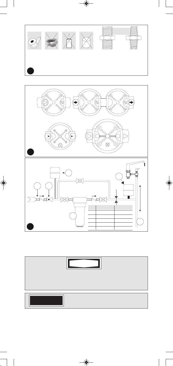
Consultar las guras:
A Informaciones generales.
B Presentación de las indicaciones IN-OUT en los distintos modelos de contenedores.
C Esquema de instalación:
1. Punto de entrada de la red hídrica | 2. Reductor de presión | 3. Sistema
anti-golpe de ariete | 4. Otras instalaciones | 5. Filtro de cualquier tipo
- Antes de la instalación, compruebe si el sistema de plomería ha sido congurado según el
código de plomería vigente.
- Evite todo tipo de tensiones usando un soporte de pared. Si fuera imposible el uso del soporte
de pared, el instalador (persona calicada y experimentada) será responsable de realizar una
instalación más adecuada para evitar tensiones que puedan afectar la integridad del ltro.
- Conecte la entrada al lado del producto con la echa IN (entrada) y la salida al lado con la
echa OUT (salida). (Figura B)
-Conecte la tubería usando conexiones decreciente únicamente si los ltros están
marcados como NPT y/o si los ltros están especicados como NPT en la etiqueta
adherida en la caja del producto. Preferentemente conecte a la tubería usando
mangueras exibles.
- Conecte a tuberías usando conexiones BSPP (paralelos) si el ltro no está marcado como NPT
o no está especicado como NPT en la etiqueta de la caja.
Preferentemente conecte a la tubería usando mangueras exibles.
- Solo use cinta de sellado como sellador para las conexiones.
- Se recomienda la instalación de un desvío (By-pass) (consulte la Figura C).
- Si el contenedor está provisto completo con cartucho, retire el envoltorio plástico protector del
cartucho antes de usarlo.
- Consulte la Figura D para las instrucciones paso a paso para la inserción de un nuevo cartucho.
- Antes de la instalación asegúrese de que los enchufes en la
inmediaciones del área estén desconectados.
- No instalar cerca de dispositivos eléctricos.
- Antes de instalar, lubrique meticulosamente la junta tórica de la
caja de protección ubicada en la parte superior de la taza.
- No lo use con agua que no sea microbiológicamente segura o de calidad
desconocida sin la adecuada desinfección previa o posterior del sistema
de ltración. Los sistemas certicados para la reducción de quistes
podrían ser usados en aguas que podrían contener quistes ltrables.
INSTRUCCIONES PARA LA
INSTALACIÓN
Y MANTENIMIENTO DE LOS FILTROS
LEA ATENTA Y CUIDADOSAMENTE LAS INSTRUCCIONES DE ESTE MANUAL Y
COMPRENDA SU CONTENIDO ANTES DE INSTALAR EL CONTENEDOR PARA FILTROS.
PRECAUCIÓN
ES
PRECAUCIÓN
Cierre la cañería principal del agua antes de la
instalación.
ADVERTENCIA
Nuvia_3P_INSTRUCTIONS.qxp_Layout 1 10/11/21 09:22 Pagina 7

8
V
12
3
Ø V
5
4
3
Solo en caso de instalación
con bomba de alimentación
TIPOS DE
ADAPTADORES
BSPP
paralelo
ISO 228
Se adapta a todos
los contenedores,
excepto a los NPT
NPT
decreciente
ANSI/ASME B1.20.1
Solo usarlo
con contenedores
NPT.
NO USE COLAS
DE PEGAR NI
SELLADORES
LÍQUIDOS
SOLO USE
CINTA
DE SELLADO
COMO
SELLADOR
NO USE
PASTA VERDE
NO USE
CÁÑAMO
ENTRADA
ENTRADA ENTRADA
ENTRADA
SALIDA
SALIDA SALIDA
SALIDA
IN
OUT
IN
VV
IN OUT
Modos de presentación de direcciones de entrada y salida (echas) en los
diferentes modelos de contenedores para ltros.
ESQUEMA DE INSTALACIÓN
Arranque
- Guarde el paquete del ltro con la etiqueta para identicar el producto.
- Asegúrese de que el sellado sea fuerte y el adecuado.
- Después de la instalación, abra el grifo y deje correr el agua por al menos 5 minutos
antes de usarla.
Uso (verique la etiqueta sobre la caja para identicar serie y modelo del ltro)
- Si usa para ltración de agua potable, no lo use para el ltrado de agua que no sea
segura o de calidad desconocida. Los sistemas certicados para la reducción de
quistes podrían ser usados en aguas que podrían contener quistes ltrables.
- Respecta los parámetros de trabajo mostrados en la etiqueta pegada al ltro.
- Si la presión excede las condiciones de trabajo, proteja el producto con un reductor
de presión.
PRECAUCIÓN
La calidad inicial del agua no será óptima a menos que
haga correr el agua por al menos 5 minutos antes de
usarla.
Asegúrese de que no haya pérdidas de agua en el producto y en especial, controle
el apriete entre la cabeza de la caja de protección y la taza de la misma. En caso
de que las hubiera, abra la caja de protección, quite la junta tórica de la taza,
coloque una nueva junta y aplique el lubricante.
A
B
C
ADVERTENCIA
ØV min V max
1/4” 0.8 gal (3 l) 1.32 gal (5 l)
1/2” 3.17 gal (12 l) 4.76 gal (18 l)
3/4” 5.28 gal (20 l) 6.60 gal (25 l)
1” 9.25 gal (35 l) 10.57 gal (40 l)
1”1/2 21.13 gal (80 l) 22.45 gal (85 l)
Nuvia_3P_INSTRUCTIONS.qxp_Layout 1 10/11/21 09:22 Pagina 8

9
- Manténgalo protegido de la luz. Use sólo modelos opacos de contenedores para la
instalación bajo de luz directa. Los ltros deben ser suministrados sólo de agua fría.
- Manténgalo protegido del calor o el frío excesivo: no exponga a temperaturas por
debajo de 39 °F (4 °C) o por encima de 113 °F (45 °C)
- Manténgalo protegido del ujo de retorno de agua caliente con una válvula de retención.
- Manténgalo protegido de golpeteos con un dispositivo anti golpeteos. En caso de
instalación en sistemas alimentados con bomba y, en concreto, en aquellos equipados
con sensor de caudal de gas, se introduce otro vaso de expansión aguas arriba del
ltro para protegerlo de posibles/continuos picos de presión.
- Si se deja el ltro (contenedor + cartucho) no en empleo durante más de 1 semana
sustituye el cartucho/s por el nuevo antes del empleo.
Operaciones de reemplazo de Cartucho para ltros
Consulte las guras y siga las instrucciones paso a paso a continuación para reemplazar
el cartucho.
Los valores de temperatura máxima de trabajo y de presión máxima de
trabajo que se indican en la etiqueta jada al contenedor del ltro están
pensados como parámetros máximos de trabajo y no se deben exceder. Si se
usa el contenedor en condiciones de presión alta pueden ocasionarse roturas.
PRECAUCIÓN
5’
D
new
new
1
4
8 9 10
5 6 7
2 3
A. Antes de abrirlo cierre la cañería principal del agua ( 1) y coloque una bandeja
debajo del sistema para que el agua que se derrame mientras se retira el cartucho
del ltro caiga adentro.
B. Libere la presión del producto desenroscando la válvula de descarga del cabezal (
2 ).
C. Abra el contenedor desenroscándolo ( 3 ).
D. Retire el cartucho usado ( 4 ).
Nuvia_3P_INSTRUCTIONS.qxp_Layout 1 10/11/21 09:22 Pagina 9

10
Resolución de problemas
FUNCIONAMIENTO
DEFECTUOSO
Filtraciones entre el
contenedor y el
cabezal del
contenedor.
Filtraciones en las
conexiones de
entrada/salida.
CAUSA
a. El contenedor no
está ajustado lo
suciente.
b. El anillo tórico (o-
ring) es viejo/está
afectado.
a. No tiene la cantidad
suciente de
sellador o la
conexión no está lo
sucientemente
ajustada.
b. Tipo de conexión no
adecuada.
SOLUCIÓN
a. Ajuste más el contenedor
con la llave de tuercas.
b. Si el contenedor aún ltra,
cambie el anillo tórico del
contenedor por uno nuevo
(use reemplazos / repuestos
originales).
a. Quite la cinta de sellado
anterior del adaptador y
coloque más cinta de sellado
o ajuste la conexión de
forma adecuada.
b. Use sólo contenedores que
coincidan con el tipo de
encastres como se indica en
la etiqueta del producto. Los
adaptadores NPT
decrecientes solo se ajustan
a los ltros con la indicación
NPT en la etiqueta. Los
adaptadores BSPP paralelos
solo se ajustan a los ltros
sin la indicación NPT en la
etiqueta.
PRECAUCIÓN
Despues de las operaciones de mantenimiento, abra el
grifo por al menos 5 minutos antes de usar el agua.
Disposición del ltro y del cartucho
Los contenedores y los cartuchos se deben disponer de acuerdo con las reglas y las
normativas vigentes.
Tras poner nuevamente en marcha, cambie la junta tórica con una nueva y
lubríquela. Asegúrese de que no haya pérdidas de agua en el producto y en
especial, controle el apriete entre la cabeza de la caja de protección y la taza de la
misma.
ADVERTENCIA
E. Limpie el contenedor con agua fría y una esponja suave.
F. Abra el envoltorio del cartucho nuevo y deséchelo ( 5).
G. Inserte el cartucho nuevo y colóquelo en el contenedor ( 6 ).
H. Ajuste el cuenco del contenedor al cabezal del contenedor usando la llave de tuercas
( 7 ). No ajuste demasiado.
I. Abra la cañería principal del agua ( 8 ).
J. Abra lentamente el suministro de agua.
K. Espere que el aire se purgue desde la válvula de descarga, luego gírela y ajústela (
9 ).
L. Deje correr el agua por al menos 5 minutos antes de usarla ( 10 ).
Mantenimiento
- Reemplace el contenedor del ltro al menos cada 5 años.
- Para mantenimiento o reemplazo de los cartuchos para ltros siga las instrucciones
del capítulo anterior.
- Si no se usa por más de 1 semana, retire el cartucho del ltro y usar un nuevo
cartucho en la re-partida.
Nuvia_3P_INSTRUCTIONS.qxp_Layout 1 10/11/21 09:22 Pagina 10

Nuvia_3P_INSTRUCTIONS.qxp_Layout 1 10/11/21 09:22 Pagina 11

Nuvia_3P_INSTRUCTIONS.qxp_Layout 1 10/11/21 09:22 Pagina 12
This manual suits for next models
1
Table of contents
Languages:
Other NUVIA Water Filtration System manuals
Popular Water Filtration System manuals by other brands

Wasserhaus
Wasserhaus QuaRO Series Installation and user manual

GE
GE Smart Water PNRV18ZWH01 installation instructions

Parkside
Parkside PFT 20 A1 Translation of the original instructions

TCi
TCi MFC A installation instructions

Sartorius
Sartorius arium 611VF Installation and operation manual

Reka
Reka EKSVO BSL-MED-1 manual

Yoshitake
Yoshitake SW-10 product manual

Parker
Parker Racor RK20025-01 quick start guide

3M
3M 3MRO401 Installation and operating instructions for

NSF
NSF Kasco CertiSafe PM-100 Assembly & installation manual

Sub-Zero
Sub-Zero WS Series quick start guide

Honeywell
Honeywell 50045947-001/011 operating instructions