Nuvoton KU-KA44143A User manual

To Contents
Page 2 of 18
KU-KA44143A
Rev 1.00November.1, 2023
KU-KA44143A Connection Tester User Manual
Disclaimer
Regarding the specifications of this product, it is considered that you have
agreed to the disclaimer described below.
1. When the application system is designed using this product, please design the system at your own risk.
Please read, consider, and apply appropriate usage notes and description in this standard.
2. When designing your application system, please take into the consideration of break down and failure
mode occurrence and possibility in semiconductor products. Measures on the systems such as, but not
limited to, redundant design, mitigating the spread of fire, or preventing glitch, are recommended in order
to prevent physical injury, fire, social damages, etc. in using the Nuvoton Technology Japan Corporation
(hereinafter referred to as NTCJ) products.
3. When using this product, for each actual application systems, verify the systems and the all functionality of
this product as intended in application systems and the safety including the long-term reliability at your own
risk
4. Please use this product in compliance with all applicable laws, regulations and safety-related requirements
that regulate the inclusion or use of controlled substances, including without limitation, the EU RoHS
Directive. NTCJ shall not be held responsible for any damage incurred as a result of this product being
used not in compliance with the applicable laws, regulations and safety-related requirements.
5. This product does not have any security functions using cryptographic algorithms, such as authentication,
encryption, tampering detection.
6. Unless this product is indicated by NTCJ to be used in applications as meeting the requirements of a
particular industry standard (e.g., ISO 9001, IATF 16949, ISO 26262, etc.), this product is neither designed
nor intended for use in such environments for that applications. NTCJ shall not be held responsible for not
meeting the requirements of a particular industry standard.
7. Using product that have been indicated as compliant with industry functional safety standards does not
warrant that the application meets the requirements of industry functional safety standards. NTCJ shall not
be held responsible for the application compliance with requirements of the particular industry functional
safety standard.
8. Unless this product is indicated by NTCJ to be used in applications as meeting the requirements of a
particular quality standard (e.g., AECQ-100, etc.), this product is neither designed nor intended for use in
such the environments for that applications. NTCJ shall not be held responsible for not meeting the
requirements of a particular quality standard.
9. In case of damages, costs, losses, and/or liabilities incurred by NTCJ arising from customer’s non-
compliance with above from 1 to 8, customer will indemnify NTCJ against every damages, costs, losses
and responsibility.

To Contents
Page 3 of 18
KU-KA44143A
Rev 1.00November.1, 2023
KU-KA44143A Connection Tester User Manual
Contents
Disclaimer P.2
1. Introduction P.4
2. Prepare items P.5
3. Connection between Motor and Tester
3-1. Connection description P.6
3-2. Connection between Motor and Tester P.7
4. How to use
4-1. How to use P.8
4-2. Swap the KE-KA44143A evaluation board P.9
4-3. What to do when fail LED lights up P.10
4-4. Countermeasures(error code ①and ②) P.11
4-5. Countermeasures(error code ③and ④) P.12
4-6. Countermeasures(error code ⑤and ⑥) P.13
4-7. Countermeasures(error code ⑦and ⑧) P.14
4-8. Countermeasures(error code ⑨and ⑩) P.15
4-9. If none of the LEDs light up P.16
5. Revision History P.17
6. Important notice P.18

To Contents
Page 4 of 18
KU-KA44143A
Rev 1.00November.1, 2023
KU-KA44143A Connection Tester User Manual
Chapter 1:Introduction
This connection tester is a support tool for driving a 3-phase BLDC motor with
KE-KA44143A evaluation board.
Power of this connection tester is supplied from a PC via USB. The connection
between the KE-KA44143A evaluation board and the motor can be determined
by connecting the 3-phase terminal and the Hall signal terminal of the motor to
the tester and rotating the motor manually.
The test result can be confirmed by the LED on the tester. If the connection are
correct, the blue color PASS LED will light up. If the connection is incorrect, the
red color FAIL LED lights up. The yellow color Error LEDs indicate the details of
the connection error, so the incorrect connection can be corrected easily.
■Overview
■Tester photo
■Connection diagram
3-phase Brushless Motor
Powered by USBConnect to motor
Check and verify the connection
with the LEDs on the tester
Connection tester


To Contents
Page 6 of 18
KU-KA44143A
Rev 1.00November.1, 2023
KU-KA44143A Connection Tester User Manual
Chapter 3:Connection between Motor and Tester
■Connection diagram
Connect the motor, connection tester, USB cable, and PC as follows.
Refer to the next page for
the connection of motor
outputs and hall signals.
IN+
IN-
OUT+
OUT- HALL
H1H
H1L
U
V
W
VH
VL
CN1
CN2
CN3
3-phase
Brushless motor
Connection tester USB Cable
(micro USB B type)
PC or USB battery
USB cable
outlet
When you connect the PC and the tester with
a USB cable, the LED shown below light up.
(Power is supplied to the tester via USB)
(note)
After connecting the PC and the tester with a USB cable,
all the LEDs will turn on for about 1 second, and then
turn off.
Please be noted that it is not a malfunction. Follow the
procedure in the remaining pages to check the
connection.
LED light up
3-1.Connection description
To Contents
Page 7 of 18
KU-KA44143A
Rev 1.00November.1, 2023
KU-KA44143A Connection Tester User Manual
3-2.Connection between Motor and Tester
H1H
VH Connection Tester
H1L
VL
U
V
W
CN2
CN1
CN3
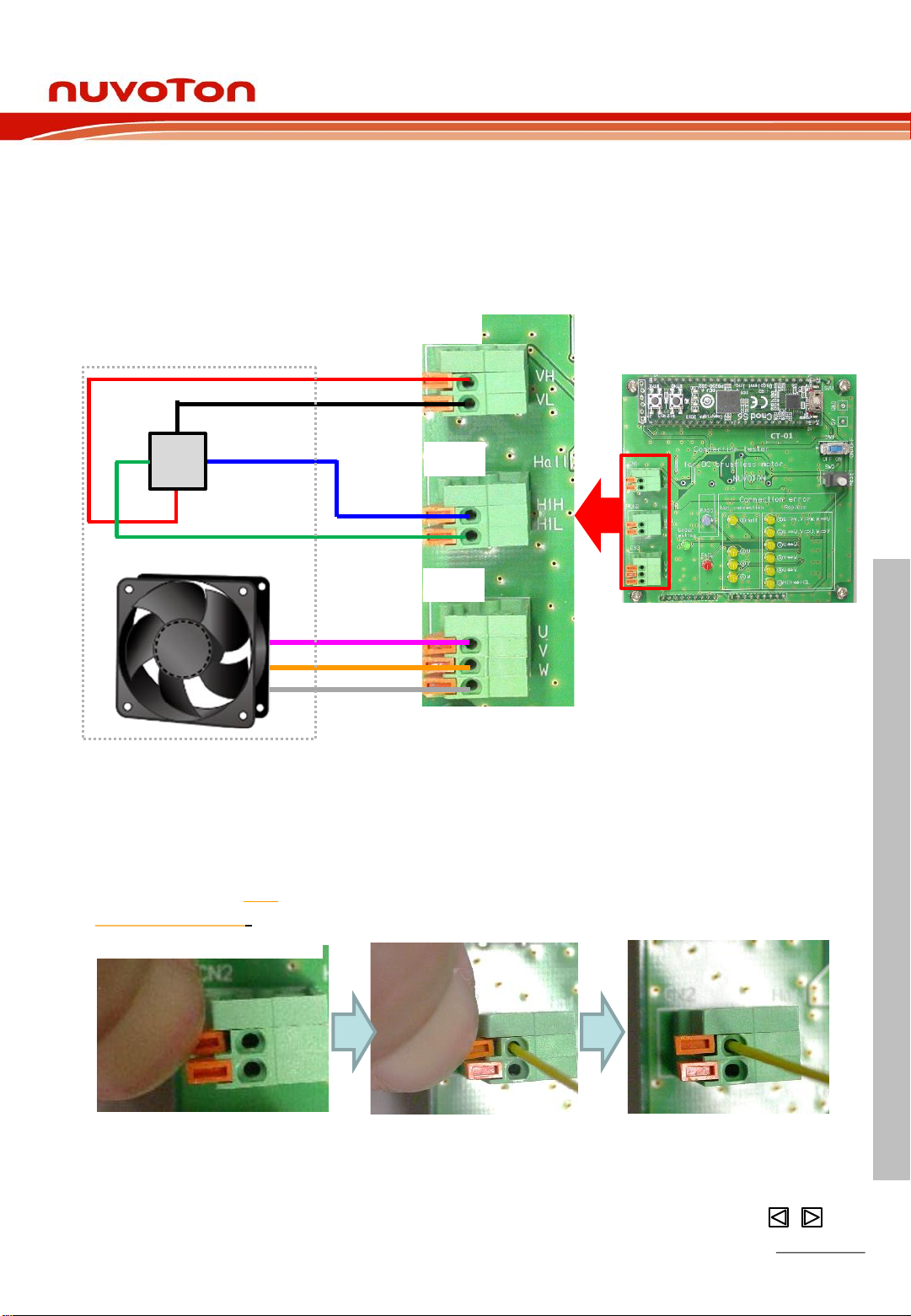
Connect the wirings between motor and tester as shown in the figure below.
IN+
IN-
OUT+
OUT-HAL
L
3-phase Brushless motor
U
V
W
■How to connect the tester connector and motor wiring
1) Press down the
orange switch on
the connector
2) Insert the motor
wiring into the hole
3) Check that the wires do
not come out of the hole.
Connect the wirings from motor to the connector on the tester as shown
in the figure below.
Connector
Chapter 3:Connection between Motor and Tester

To Contents
Page 8 of 18
KU-KA44143A
Rev 1.00November.1, 2023
KU-KA44143A Connection Tester User Manual
Chapter 4:How to use
4-1.How to use
Step (1) Power on
Step (2) Rotate the motor by hand
Step (3) Reset
Step (4) Check LEDs for connection confirmation
Reconnect the wirings to the
KE-KA44143A evaluation
board, as shown in next
page
Correct the connection according to the
error code table in Page 11 and repeat
the steps from Step (1).
SW1
SW2 Push SW2 knob
once while the
motor is rotating.
ON
OFF Slide the SW1
knob to the right
FAIL LED lights up
PASS LED lights up
Please follow the steps below to check the connection
Rotate the motor
in the desired
rotation direction
by hand for at
least 2 turns.
Step (5) Power off
Slide the SW1
knob to the left to
POWER OFF
SW1
ON
OFF
Step (6) Reconnect to
KE-KA44143 EVB
Step (5) Power off
Slide the SW1
knob to the left
to POWER OFF
SW1
ON
OFF
Step (6) Correct according to
the error code
In case of FAIL, repeat from Step (1)
Step(2)
SW1
SW2
Step(1)
(5)
Step(3)
Step(4)
Check LEDs
PASS
lights up
FAIL
Lights up Error
code
LEDs
Rotate
by hand
Go to next page

To Contents
Page 9 of 18
KU-KA44143A
Rev 1.00November.1, 2023
KU-KA44143A Connection Tester User Manual
4-2. Swap the KE-KA44143A evaluation board
IN+
IN-
OUT-
If the PASS LED lights up, disconnect the motor wires from the tester
one at a time,
H1H
H1L
U
V
W
VH
VL
H1L
VH
VL
H1H
HALL
Reconnect the wire to the terminal on the KE-KA44143A evaluation
board with the same name accordingly
U
V
W
Tester
Motor
Motor
KE-KA44143A Evaluation Board
With this, the connection setting is completed. Now, KE-
KA44143A EVB is ready to drive the motor. Experience the
stable and high efficiency driving with KA44143A.
Connect to the same
terminal name
PASS
Lights up
IN+
IN-
OUT+
OUT- HALL
OUT+
H1H
H1L
U
V
W
VH
VL
U
V
W
H1L
VH
VL
H1H
Enlarge the connector
Connector Connector
Enlarge the connector
Chapter 4:How to use
Connector
To Contents
Page 10 of 18
KU-KA44143A
Rev 1.00November.1, 2023
KU-KA44143A Connection Tester User Manual
4-3. What to do when fail LED lights up
Error Code Error details Countermeasure Page
FAIL
①
Signal
Input
error
Hall signal Check connection of the Hall signal
(VH, VL, H1H, H1L) P.12
②Motor U Check connection of the motor U P.12
③Motor V Check connection of the motor V P.13
④Motor W Check connection of the motor W P.13
⑤
Wrong
connection
Motor
U,V,W
Reconnect the connection
U⇒V, V⇒W, W⇒UP.14
⑥Motor
U,V,W
Reconnect the connection
U⇒W, V⇒U, W⇒VP.14
⑦Motor
U,W
Reconnect the connection
between motor U and W P.15
⑧Motor
V,W
Reconnect the connection
between motor V and W P.15
⑨Motor
U,V
Reconnect the connection
between motor U and V P.16
⑩Hall signal Reconnect the connection
between Hall H1H and H1L P.16
No light
Open connection
for all wiring.
No power input.
Check connection of all wiring.
Confirm that the power is applied
and SW1 is ON.
P.17
FAIL
LED
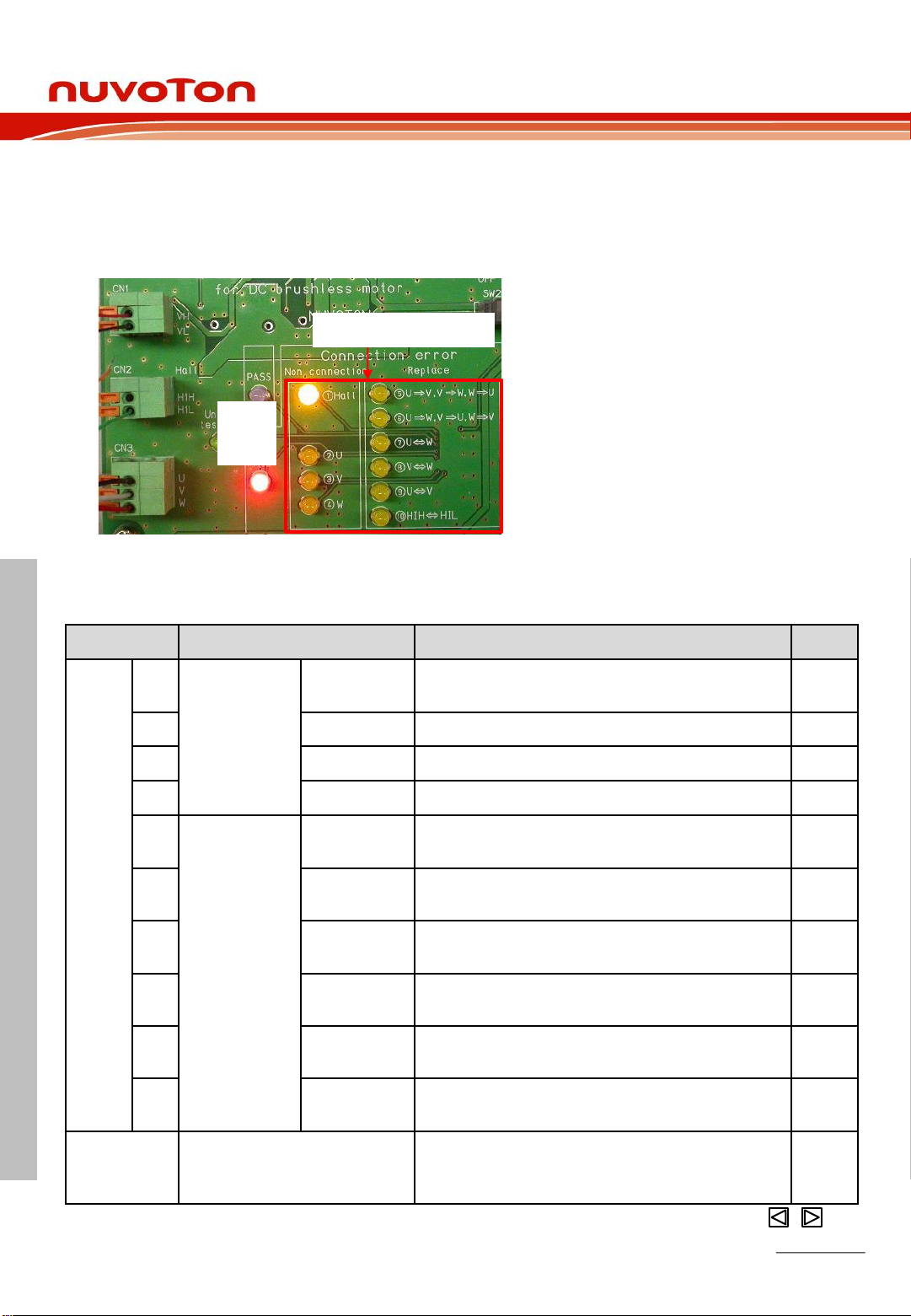
Correct the connection according to the error code table below.
The corrective action for the error code LED differs depending on the LED.
A list of error code LEDs is shown in the table below, so refer to the
corresponding section.
Error code LEDs If the connection is incorrect, the FAIL
LED and the corresponding error code
LEDs will light up at the same time.
(note)
Multiple error code LEDs may light up.
In this case, please deal with all the
wrong connections indicated by
error code LEDs.
Chapter 4:How to use

To Contents
Page 11 of 18
KU-KA44143A
Rev 1.00November.1, 2023
KU-KA44143A Connection Tester User Manual
4-4.Countermeasures(error code ①and ②)
If the error code LED lights up, please take the following countermeasures.
Hall signals (VH, VL, H1H, H1L
terminals) are not connected
correctly.
Check the connection of hall signals
(VH, VL, H1H, H1L)
【Error code ①lights up】
■Error contents
■Countermeasures
Check the connection of hall signals
(VH, VL, H1H, H1L)
Make sure that the LED is lit as
shown below.
CN3
Check the U terminal connection
【Error code ②lights up】
■Error contents
■Countermeasures
Make sure that the LED is lit as
shown below.
The U terminal is not connected
correctly.
Check the connection of the U
terminal.
FAIL
Error code ①
CN3
U
V
W
U
V
W
Error code ②
FAIL
CN2
CN1
IN+
IN-
OUT+
OUT-
Hall element
CN2
CN1
IN+
IN-
OUT+
OUT-
Hall element
H1H
H1L
VH
VL
H1H
H1L
VH
VL
U terminal
open
Open
Chapter 4:How to use
To Contents
Page 12 of 18
KU-KA44143A
Rev 1.00November.1, 2023
KU-KA44143A Connection Tester User Manual
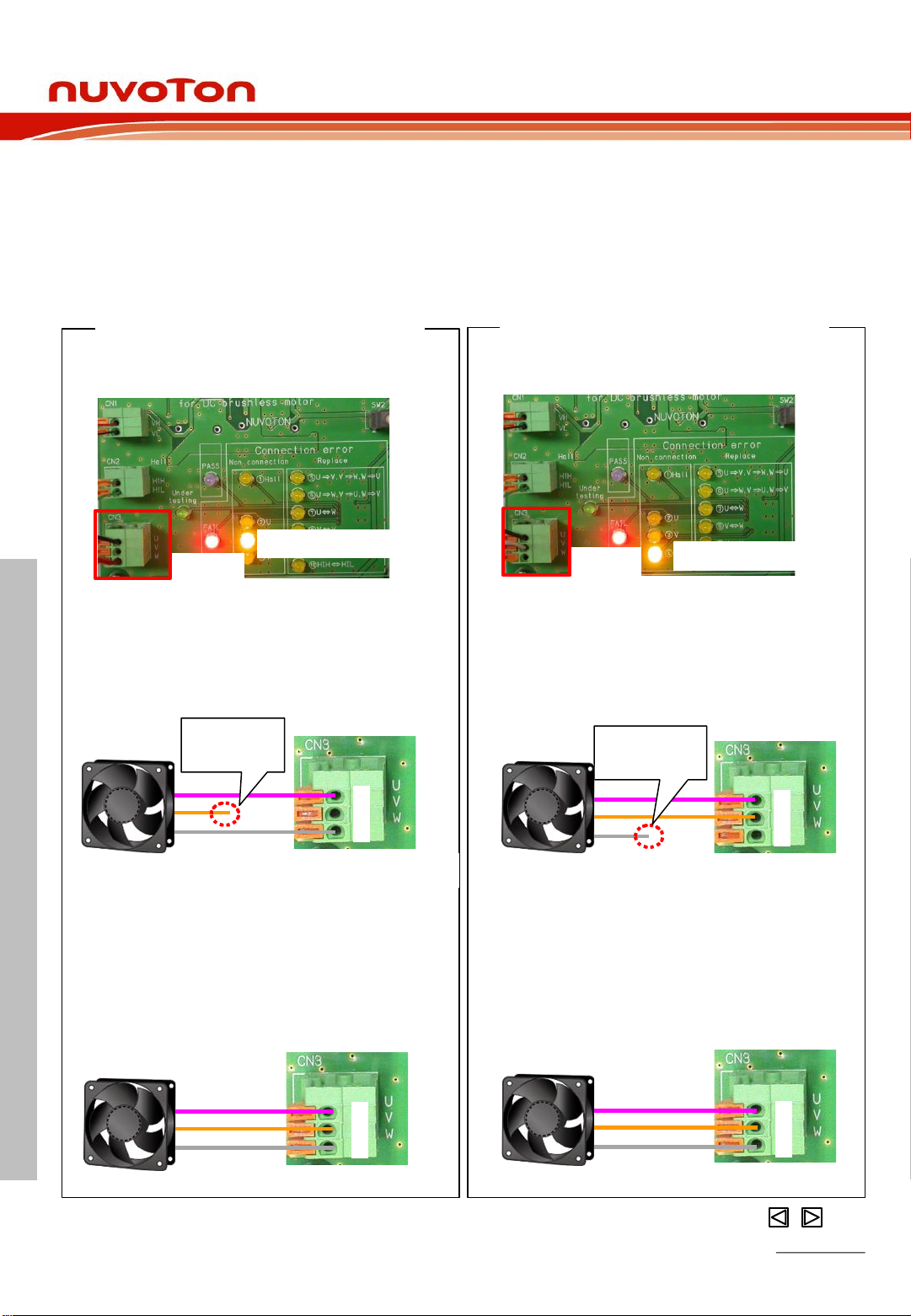
4-5.Countermeasures(error code ③and ④)
If the error code LED lights up, please take the following countermeasures.
【Error code ③lights up】
Make sure that the LED is lit as
shown below.
【Error code ④lights up】
Make sure that the LED is lit as
shown below.
Error code ③
FAIL Error code ④
FAIL
The V terminal is not connected
correctly.
Check the connection of the V
terminal.
CN3
Check the V terminal connection
U
V
W
CN3
U
V
W
V terminal
open
The W terminal is not connected
correctly.
Check the connection of the W
terminal.
CN3
Check the W terminal connection
U
V
W
CN3
U
V
W
W terminal
open
Chapter 4:How to use
■Error contents
■Countermeasures
■Error contents
■Countermeasures

To Contents
Page 13 of 18
KU-KA44143A
Rev 1.00November.1, 2023
KU-KA44143A Connection Tester User Manual
4-6.Countermeasures(error code ⑤and ⑥)
If the error code LED lights up, please take the following countermeasures.
Make sure that the LED is lit as
shown below.
Make sure that the LED is lit as
shown below.
U, V, W terminals are not connected
correctly
Reconnect the U, V, W terminal
connections.
U⇒V, V⇒W, W⇒U CN3
U
V
W
U, V, W terminals are not connected
correctly
Reconnect the U, V, W terminal
connections.
U⇒W, V⇒U, W⇒V CN3
U
V
W
Error code ⑤
FAIL
Error code ⑥
FAIL
U
V
W
CN3
U
V
W
CN3
U,V,W terminal
misconnection
U,V,W terminal
misconnection
Chapter 4:How to use
【Error code ⑤lights up】 【Error code ⑥lights up】
■Error contents
■Countermeasures
■Error contents
■Countermeasures

To Contents
Page 14 of 18
KU-KA44143A
Rev 1.00November.1, 2023
KU-KA44143A Connection Tester User Manual
CN3
U
V
W
CN3
U
V
W
Error code ⑦
FAIL
Error code ⑧
FAIL
U
V
W
U
V
W
U,W terminal
misconnection V,W terminal
misconnection
4-7.Countermeasures(error code ⑦and ⑧)
If the error code LED lights up, please take the following countermeasures.
Make sure that the LED is lit as
shown below.
Make sure that the LED is lit as
shown below.
Chapter 4:How to use
【Error code ⑦lights up】 【Error code ⑧lights up】
U, W terminals are not connected
correctly
Reconnect the U and W terminal
connections.
U⇒W, W⇒U
V, W terminals are not connected
correctly
Reconnect the V and W terminal
connections.
V⇒W, W⇒V
■Error contents
■Countermeasures
■Error contents
■Countermeasures

To Contents
Page 15 of 18
KU-KA44143A
Rev 1.00November.1, 2023
KU-KA44143A Connection Tester User Manual
U, V terminals are not connected
correctly
Reconnect the U and V terminal
connections.
U⇒V, V⇒U CN3
U
V
W
H1H, H1L terminals are not connected
correctly
Reconnect the H1H and H1L terminal
connections.
H1H⇒H1L, H1L⇒H1H
Error code ⑨
FAIL Error code ⑩
FAIL
OUT+
OUT-
CN2
CN3
U
V
W
H1H,H1L terminal
misconnection
U,V terminal
misconnection
OUT+
OUT-
Hall element
CN2
4-8.Countermeasures(error code ⑨and ⑩)
If the error code LED lights up, please take the following countermeasures.
Make sure that the LED is lit as
shown below.
Chapter 4:How to use
【Error code ⑨lights up】 【Error code ⑩lights up】
■Error contents
■Countermeasures
■Error contents
■Countermeasures
Make sure that the LED is lit as
shown below.
Hall element

To Contents
Page 16 of 18
KU-KA44143A
Rev 1.00November.1, 2023
KU-KA44143A Connection Tester User Manual
4-9.If none of the LEDs light up
If none of the LEDs light up, please check the followings.
In this case, it could be because:
・All motor wirings are open
・SW1 is not turned on
・The USB cable is not connected to the tester or PC.
Please confirm if the above are properly and correctly done.
Make sure all wiring
from the motor are
connected
Make sure SW1
is ON
Make sure the USB cable
is connected to the tester
3-phase Brushless Motor
H1H
H1L
U
V
W
VH
VL
ON
OFF
Tester
SW1
IN+
IN-
OUT+
OUT-HALL
USB cable
outlet
Chapter 4:How to use


To Contents
Page 18 of 18
KU-KA44143A
Rev 1.00November.1, 2023
KU-KA44143A Connection Tester User Manual
Important Notice
Nuvoton Products are neither intended nor warranted for usage in systems or equipment, any
malfunction or failure of which may cause loss of human life, bodily injury or severe property damage.
Such applications are deemed, “Insecure Usage”.
Insecure usage includes, but is not limited to: equipment for surgical implementation, atomic energy
control instruments, airplane or spaceship instruments, the control or operation of dynamic, brake or
safety systems designed for vehicular use, traffic signal instruments, all types of safety devices, and
other applications intended to support or sustain life.
All Insecure Usage shall be made at customer’s risk, and in the event that third parties lay claims to
Nuvoton as a result of customer’s Insecure Usage, customer shall indemnify the damages and
liabilities thus incurred by Nuvoton.
Table of contents


