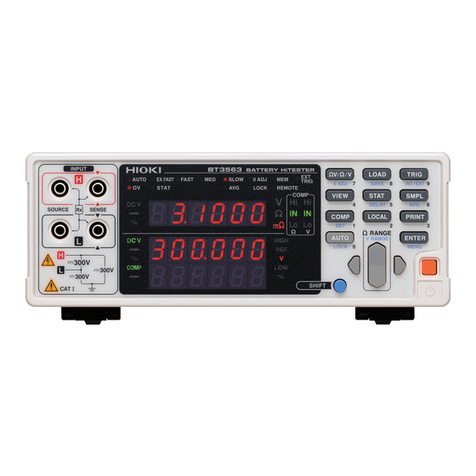
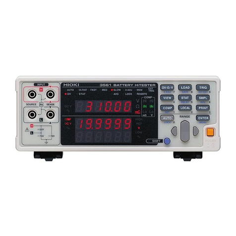
Hioki 3541 User manual

RESISTANCE HiTESTER
INSTRUCTION MANUAL
3541


Contents
i
Contents
Introduction.................................................................................1
Inspection ...................................................................................1
Safety Information ......................................................................2
Operating Precautions................................................................4
Chapter 1
Overview ___________________________________ 9
1.1 Product Overview..........................................................9
1.2 Features ........................................................................9
1.3 Names and Functions of Parts....................................11
Chapter 2
Measurement Preparations___________________ 17
2.1 Procedure....................................................................17
2.2 Connecting the Power Cord ........................................18
2.3 Connecting the Test Leads .........................................19
2.4 Connecting the Temperature Probe............................21
2.5 Connecting an Analog Output Thermometer ..............22
2.6 Connecting the Temperature HiTester via RS-232C ..23
2.7 Turning the Power On and Off ....................................24
2.8 Selecting the Line Frequency......................................25
2.9 Selecting the Measurement Terminals........................26
Chapter 3
Measurement ______________________________ 29
3.1 Resistance Measurement ...........................................29
3.2 Temperature Measurement
(Temperature Correction & Conversion) .....................31
Chapter 4
Basic Function Settings _____________________ 37
4.1 Selecting Measurement Functions ..............................37
4.2 Measurement Range Setting ......................................38
4.3 Zero-Adjust Function...................................................40
4.4 Sampling Rate Setting ................................................42
4.5 Measurement Fault Detection Function ......................43
4.6 Overflow Display .........................................................44

Contents
ii
Chapter 5
Applied Function Settings____________________ 45
5.1 Comparator Measurement Function........................... 45
5.2 BIN Measurement Function........................................ 51
5.3 Averaging Function..................................................... 57
5.4 Temperature Correction Function (TC) ...................... 58
5.5 Temperature Conversion Function (∆t) ...................... 60
5.6 Statistical Calculation Functions................................. 62
5.7 Offset Voltage Compensation (OVC) ......................... 65
5.8 Self-Calibration ........................................................... 66
5.9 Key Beeper Setting..................................................... 67
5.10 Key-Lock Function...................................................... 67
5.11 Trigger Function ......................................................... 68
5.11.1 Trigger Source .............................................................. 68
5.11.2 Trigger Delay ................................................................ 69
5.12 Panel Save Function .................................................. 71
5.13 Panel Load Function................................................... 72
5.14 Reset Function ........................................................... 73
5.15 Valid Functions for Each State ................................... 75
Chapter 6
External Control ____________________________77
6.1 External Control and the External Input/Output (EXT I/O)
Connector ................................................................... 77
6.2 Signal Descriptions..................................................... 78
6.3 Timing Chart ............................................................... 83
6.4 Internal Circuitry ......................................................... 85
Chapter 7
Printer (Optional) ___________________________87
7.1 About Printing ............................................................. 87
7.2 Printer Connection...................................................... 88
7.3 Interface Selection...................................................... 92
7.4 Setting of the 9670 PRINTER..................................... 92
7.5 Printing ....................................................................... 93

Contents
iii
Chapter 8
RS-232C/GP-IB Interfaces ____________________ 95
8.1 Overview and Features ...............................................95
8.2 Specifications ..............................................................96
8.2.1 RS-232C Specifications ................................................96
8.2.2 GP-IB Specifications .....................................................96
8.3 Connections and Protocol Selection ...........................97
8.3.1 Attaching the Connector ................................................97
8.3.2 Communications Protocol Selection ..............................99
8.4 Communication Methods ..........................................100
8.4.1 Message Format .........................................................100
8.4.2 Output Queue and Input Buffer ...................................105
8.4.3 Status Byte Register ...................................................106
8.4.4 Event Registers ...........................................................108
8.4.5 Initialization Items ........................................................111
8.4.6 Local Function .............................................................111
8.5 Message List .............................................................112
8.5.1 Standard Commands ..................................................112
8.5.2 Device-Specific Commands ........................................113
8.6 Message Reference ..................................................118
8.6.1 Standard Commands ..................................................119
8.6.2 Device-Specific Commands ........................................123
8.7 Basic Data Importing Methods ..................................147
8.8 Sample Programs .....................................................148
Chapter 9
Specifications_____________________________ 159
9.1 General Specifications ..............................................159
9.2 Accuracy ...................................................................164
Chapter 10
Maintenance and Service ___________________ 167
10.1 Inspection, Repair and Cleaning ...............................167
10.2 Error Display .............................................................168
Appendix_________________________________ 169
Appendix 1 Four-Terminal (Voltage-Drop) Method............169
Appendix 2 Temperature Correction Function (TC)...........170
Appendix 3 Temperature Conversion Function (∆t)...........172
Appendix 4 Effect of Thermoelectromotive Force..............173
Contents
iv
Appendix 5 JEC 2137-Compliant Resistance Measurement
of Inductive Machines..................................... 175
Appendix 6 Test Lead Options.......................................... 176
Appendix 7 Rack Mounting ............................................... 178
Appendix 8 Dimensional Diagram..................................... 180
Index ______________________________________ i

1
Introduction
Introduction
Thank you for purchasing the HIOKI “Model 3541 RESISTANCE
HiTESTER". To obtain maximum performance from the instrument,
please read this manual carefully, and keep it handy for future
reference.
Inspection
Confirming
package contents
When you receive the instrument, inspect it carefully to ensure that no
damage occurred during shipping. In particular, check the
accessories, panel switches, and connectors. If damage is evident, or
if it fails to operate according to the specifications, contact your dealer
or Hioki representative.
Instrument 3541 RESISTANCE HiTESTER
Accessories • 9287 CLIP TYPE LEAD .........................................1
• 9451 TEMPERATURE PROBE..............................1
• Instruction Manual..................................................1
• Power Cord (2-line + ground).................................1
• EXT I/O Male Connector ........................................1
Shipping
precautions
Use the original packing materials when transporting the instrument, if
possible.
Options
Test-Lead-Related
(Page 176)
• 9452 CLIP TYPE LEAD
• 9453 FOUR TERMINAL LEAD
• 9455 PIN TYPE LEAD (for ultra precision)
• 9461 PIN TYPE LEAD
• 9465 PIN TYPE LEAD
• 9467 LARGE CLIP TYPE LEAD
• 9454 ZERO ADJUSTMENT BOARD
• 9300 CONNECTION CABLE (Available Soon)
Interface
Cable
• 9637 RS-232C CABLE (9-pin to 9-pin/cross cable)
• 9638 RS-232C CABLE (9-pin to 25-pin/cross cable)
• 9151-02 GP-IB CONNECTOR CABLE (2 m)
• 9151-04 GP-IB CONNECTOR CABLE (4 m)
Printer-Related • 9670 PRINTER (BL-80RS II, made by SANEI ELECTRIC INC.)
• 9671 AC ADAPTER (for the 9670, BL-100W, made by SANEI
ELECTRIC INC.)
• 9672 BATTERY PACK (for the 9670)
• 9673 BATTERY CHARGER (for the 9672)
• 9237 RECORDING PAPER (80 mm x 25 m, 4 rolls, for the 9670)
• 9638 RS-232C CABLE (for 3541-9670)

Safety Information
2
Safety Information
This manual contains information and warnings essential for safe
operation of the instrument and for maintaining it in safe operating
condition. Before using it, be sure to carefully read the following safety
precautions.
Safety Symbols
The following symbols in this manual indicate the relative importance
of cautions and warnings.
Other Symbols
This instrument is designed to comply with IEC 61010 Safety
Standards, and has been thoroughly tested for safety prior to
shipment. However, mishandling during use could result in injury
or death, as well as damage to the instrument. Be certain that you
understand the instructions and precautions in the manual
before use. We disclaim any responsibility for accidents or
injuries not resulting directly from product defects.
In the manual, the symbol indicates particularly important
information that the user should read before using the
instrument.
The symbol printed on the instrument indicates that the user
should refer to a corresponding topic in the manual (marked with
the symbol) before using the relevant function.
Indicates AC (Alternating Current).
Indicates the ON side of the power switch.
Indicates the OFF side of the power switch.
Indicates that incorrect operation presents a significant
hazard that could result in serious injury or death to the
user.
Indicates that incorrect operation presents a possibility of
injury to the user or damage to the instrument.
Indicates advisory items related to performance or correct
operation of the instrument.
Indicates a prohibited action.
Indicates the location of reference information.
Indicates quick references for operation and remedies for
troubleshooting.
*Indicates that descriptive information is provided below.

3
Safety Information
Overvoltage Categories (CAT)
This instrument complies with CAT II (power supply section) safety
requirements.
To ensure safe operation of measurement instruments, IEC 60664
establishes safety standards for various electrical environments,
categorized as CAT I to CAT IV, and called overvoltage categories.
These are defined as follows.
Higher-numbered categories correspond to electrical environments
with greater momentary energy. So a measurement device designed
for CAT III environments can endure greater momentary energy than a
device designed for CAT II.
Using a measurement instrument in an environment designated with a
higher-numbered category than that for which the instrument is rated
could result in a severe accident, and must be carefully avoided.
Accuracy We define measurement tolerances in terms of f.s. (full scale), rdg.
(reading) and dgt. (digit) values, with the following meanings:
CAT I Secondary electrical circuits connected to an AC electrical
outlet through a transformer or similar device.
CAT II Primary electrical circuits in equipment connected to an AC
electrical outlet by a power cord (portable tools, household
appliances, etc.)
CAT III Primary electrical circuits of heavy equipment (fixed
installations) connected directly to the distribution panel, and
feeders from the distribution panel to outlets.
CAT IV The circuit from the service drop to the service entrance, and
to the power meter and primary overcurrent protection device
(distribution panel).
f.s. (maximum display value or scale length)
The maximum displayable value or scale length. This is usually the
name of the currently selected range.
rdg. (reading, displayed or indicated value)
The value currently being measured and indicated on the measuring
instrument.
dgt. (resolution)
The smallest displayable unit on a digital measuring instrument, i.e.,
the input value that causes the digital display to show a "1" as the
least-significant digit.

Operating Precautions
4
Operating Precautions
Follow these precautions to ensure safe operation and to obtain the
full benefits of the various functions.
• Before using the instrument the first time, verify that it operates
normally to ensure that the no damage occurred during storage or
shipping. If you find any damage, contact your dealer or Hioki
representative.
• Before using the instrument, make sure that the insulation on the
probes and cables is undamaged and that no bare conductors are
improperly exposed. Using the instrument in such conditions could
cause an electric shock, so contact your dealer or Hioki
representative for replacements.
Before Use
Handling the Instrument
• Do not allow the instrument to get wet, and do not take
measurements with wet hands. This may cause an electric
shock.
• Never modify the instrument. Only Hioki service engineers
should disassemble or repair the instrument. Failure to observe
these precautions may result in fire, electric shock, or injury.
• Do not use the instrument where it may be exposed to
corrosive or combustible gases. The instrument may be
damaged or cause an explosion.
To avoid damage to the instrument, protect it from physical shock
when transporting and handling. Be especially careful to avoid
physical shock from dropping.

5
Operating Precautions
• Avoid stepping on or pinching cables, which could damage the cable
insulation.
• To avoid breaking the cables and test leads, do not bend or pull
them.
• To avoid damaging the power cord, grasp the plug, not the cord,
when unplugging it from the power outlet.
• The sensor used in the temperature probe is a thin, precision
platinum film. Be aware that excessive voltage pulses or static
discharges can destroy the film.
• Avoid subjecting the temperature probe tip to physical shock, and
avoid sharp bends in the leads. These may damage the probe or
break a wire.
• When measuring high temperatures, do not let the handle of the
temperature probe or the compensation lead wire exceed the
temperature range.
Handling the Cords and Probes
Use only the specified test leads and cables. Using a non-specified
cable may result in incorrect measurements due to poor connection
or other reasons.
Instrument Installation and Operating Environment
• Do not install the instrument upside-down, or stand it on its side.
• Do not store or use the instrument where it could be exposed to
direct sunlight, high temperature or humidity, or condensation. Under
such conditions, the instrument may be damaged and insulation may
deteriorate so that it no longer meets specifications.
• This instrument is designed for use indoors. It can be operated at
temperatures between 0 and 40°C without degrading safety.
• This instrument is not designed to be entirely water- or dust-proof.
Do not use it in an especially dusty environment, nor where it might
be splashed with liquid. This may cause damage.
• Do not use the instrument near a source of strong electromagnetic
radiation, or near a highly electrically charged object. These may
cause a malfunction.
• Correct measurement may be impossible in the presence of strong
magnetic fields, such as near transformers and high-current
conductors, or in the presence of strong electromagnetic fields
such as near radio transmitters.
• In an electrically noisy environment, noise may impinge upon the
measured object, resulting in unstable measurements. The
instrument should not be used in such places.

Operating Precautions
6
Before Connecting and Powering On
Power and Grounding
• Before turning the instrument on, make sure the supply voltage
matches that indicated on the its power connector. Connection
to an improper supply voltage may damage the instrument and
present an electrical hazard.
• To avoid electrical accidents and to maintain the safety
specifications of this instrument, connect the power cord only
to a 3-contact (two-conductor + ground) outlet.
Connections
To avoid electric shock or damage to the equipment, always
observe the following precautions when connecting to external
terminals or connectors.
• Always turn off the power to the instrument and to any devices
to be connected before making connections.
• Be careful to avoid exceeding the ratings of external terminals
and connectors.
• During operation, a wire becoming dislocated and contacting
another conductive object can be serious hazard. Make sure
that connections are secure and use screws to secure the
external connectors.
To suppress noise, the instrument needs to be set to match the
frequency of the power source.
Before operating, set the instrument to the frequency of your
commercial power. If the line frequency is not set properly,
measurements will be unstable.
❖2.8 Selecting the Line Frequency (Page 25)

7
Operating Precautions
Measurement Precautions
Observe the following to avoid electric shock and damage to the
instrument.
• Do not apply voltage to the input terminals (INPUT A and INPUT
B). Also, to avoid electrical accidents, only take measurements
after turning off the power to the circuit being measured.
• Do not allow voltage of 2 V DC or more to be applied to the TC
SENSOR jack.
• Never attempt to measure at a point where voltage is present.
In particular, be careful to avoid damaging the instrument from
inductor discharge when attempting to measure a transformer or
motor immediately after a temperature increase test or withstand-
voltage test.
• The input terminals incorporate a circuit protection fuse.
Measurement is not possible when the fuse is blown.
• In the 20 mΩand 200 mΩranges, the test object can be loaded with
one watt or more. Also, in the 100 kΩrange and above, 10 volts or
more may be applied. Therefore, when measuring delicate
components, use the Low-Power Resistance Measurement mode.
• Allowable input voltage from an analog thermometer is 0 to 2 V
(between terminal contacts). Do not apply voltage exceeding this
range.
• Battery internal resistance cannot be measured with this instrument.
It will sustain damage. To measure battery internal resistance, we
recommend the HIOKI 3550, 3551 and 3555 BATTERY HiTESTERs
or the 3560 AC mΩHiTESTER.

Operating Precautions
8
• To ensure certified measurement accuracy, allow at least 60
minutes warm-up. Within the 30- to 60-minute warm-up period,
please double specified accuracy values. After warm-up, be sure
to execute self-calibration.
❖5.8 Self-Calibration (Page 66)
• This instrument internally stores (backs up) all settings (except
measurement values), such as measurement range, comparator
settings and etc., but only when no operation is performed for a
certain time. Therefore, to preserve settings, do not turn the power
off for a short time (about five seconds) after changing a setting.
However, measurement settings made through the RS-232C or
GP-IB interface and measurement settings loaded by LOAD
signals of the external I/O terminal are not memorized.
• The direct current that this instrument uses for measuring is
affected by thermoelectromotive force, which can cause
measurement aberrations. In such cases, use the Offset Voltage
Compensation function.
❖5.7 Offset Voltage Compensation (OVC) (Page 65)
❖Appendix 4 Effect of Thermoelectromotive Force (Page 173)
• When measuring objects with a large inductance (L-content) such
as power transformers, the measured value may be unstable. In
such cases, contact your dealer or Hioki representative.
Using the Temperature Probe
• Holding the temperature probe in a bare hand can cause enough
noise pickup to destabilize measurements.
• Temperature Correction does not work if the temperature probe is
allowed to touch the test object. Only the ambient temperature of
the immediate locale should be used.
• Before measuring, install the temperature probe and allow at least
60 minutes warm-up before measurement. Unless the test object
and temperature probe used for temperature correction
measurement have been allowed to completely stabilize at
ambient temperature, large measurement errors may occur.
• Unless the temperature probe is inserted all the way into the TC
SENSOR jack on the rear panel of the instrument, large
measurement errors may occur.

9
1.1 Product Overview
The 3541 employs a four-terminal measurement method that is ideal
for measuring the resistance of motor and transformer windings, relay/
switch and connector contacts, PCB patterns, chip inductor DC
resistance and for ohmmeter shipping inspection tests. The instrument
includes functions for temperature correction, comparator decisions
and data output, making it particularly suitable for production and
inspection lines, as well as for system applications.
The 4-terminal method enables precise, fast measurement of
resistances as small as 0.1 µΩ.
In addition, resistance measurements can be made as in as little as
0.6 ms.
Removes the effects of thermoelectromotive force on measurements.
Minimizes stress on test objects.
A multipolar connector (INPUT B) shielded from thermoelectromotive
force is provided to facilitate fast measurements.
By connecting a temperature probe, temperature correction of
resistance measurements is available for practically any temperature
and thermal coefficient. A thermometer with analog output can be
used in place of the supplied 9451 TEMPERATURE PROBE.
Overview Chapter 1
1.1 Product Overview
1.2 Features
High Precision, Fine Resolution and Fast Resistance
Measurement
Offset Voltage Compensation
Low-Power Measurement Function
Multipolar Connector
Broad Temperature Correction Support

1.2 Features
10
The temperature increase (∆t) of a test object can be obtained by
conversion of its measured resistance.
Maximum value (Max), minimum value (Min), mean value (Average),
overall standard deviation (σ), and process capability indices (Cp and
Cpk) can be calculated.
The Comparator function provides product pass/fail decisions. And the
BIN function provides classification into up to ten categories.
Store up to 30 sets of measurement settings such as comparator
tables, measurement ranges and sampling rates for later recall.
Various trigger inputs and comparator, BIN and BCD outputs are
provided to support production line applications.
Full remote control is available through the GP-IB and RS-232C
interfaces.
Connect the optional HIOKI 9670 PRINTER to print out measurement
values and statistical calculation results.
Temperature Conversion
Statistical Calculation Functions
Comparator and BIN Functions
Save and Load up to 30 Sets of Measurement Setting
States
External I/O
Equipped with GP-IB and RS-232C Standard Interfaces
Prints Measurement Values and Calculation Results
(Printer Optional)

11
1.3 Names and Functions of Parts
Front Panel
POWER Switch
Turns the instrument on
and off.
: Power OFF
: Power ON
❖(Page 24)
Input Terminals INPUT A
Connect the supplied 9287 CLIP TYPE
LEAD or optional measurement leads.
❖Connections: (Page 19) Operating Keys
❖(Page 13)
Input Terminals INPUT B
Connect a multipolar plug.
❖Connections: (Page 19)
Display
Sub Display
❖(Page 12)
SOURCE-H
SOURCE-L
SENSE-H
SENSE-L
Display
Main Display
❖(Page 12)

1.3 Names and Functions of Parts
12
Main Display
HIGH / LOW Indicates that absolute value comparator
operation is enabled (while measuring), and
also when setting.
REF / % Indicates that relative value comparator
operation is enabled (while measuring), and
also when setting.
°C / ppm Indicates that the temperature correction or
compensation value is displayed (while
measuring), and also when setting.
Units of
displayed
measurement
Shows measured
value or setting
item.
(Upper row)
AUTO Lit when measuring with Auto-Ranging.
FAST, MED, SLOW1, SLOW2
The selected sampling rate is lit.
0 ADJ Lit when measuring in a range for
which zero-adjustment has been
performed.
OVC Lit when measuring with the Offset
Voltage Compensation function
enabled.
EXT TRIG Lit when the manual trigger mode is
enabled.
(Lower row)
STAT Lit when the Statistical Calculation
function is enabled.
TC Lit when the Temperature Correction
function is enabled.
∆tLit when the Temperature Conversion
function is enabled.
AVG Lit when measuring with the Averaging
setting enabled.
LOCK Lit when the keys are locked.
REMOTE Lit during communications.
LP
Indicates Low-Power
measurement
mode.
Shows Comparator Decision Result.
Hi Indicates that the measured value
is above the upper threshold.
IN Indicates that the measured value
is between the upper and lower
thresholds.
Lo Indicates that the measured value
is below the lower threshold.
Displays the current measurement function, measured value (while measuring) or setting item
(while setting).
Upper and lower thresholds and other settings are displayed (when set).
Sub Display
COMP
While measuring,
indicates the Comparator
function is enabled.
BIN
While measuring,
indicates the BIN
function is enabled.
INPUT
Indicates the selected
measurement terminals.

13
1.3 Names and Functions of Parts
Operating Keys
To use a function marked on a
key, just press the key.
To use a function printed under
a key (blue letter), press the
SHIFT key first (and confirm
the SHIFT lamp is lit),
and then the key.
Operating Key Description
Ω/LPΩ/°C Select the measurement function (4-
terminal resistance, low-power 4-
terminal resistance or temperature
measurement).
[ 0 ADJ ] Executes zero-adjustment.
LOAD Loads saved settings.
[ SAVE ] Saves settings.
TRIG Use for manual triggering.
[ INT/EXT ] Selects internal/external triggering.
TC/∆tSwitches Temperature Correction or
Temperature Conversion on and off.
[ SET ] Sets parameters for Temperature
Correction or Temperature
Conversion.
STAT Displays and sets statistical
calculation results.
[ DELAY ] Sets the trigger delay.
SMPL Selects the sampling rate.
[ AVG ] Activates Averaging function
settings.
COMP Switches the Comparator function on
and off.
[ SET ] Activates Comparator function
setting.
BIN Switches the BIN function on and off.
[ SET ] Activates BIN function setting.
Operating Key Description
PRINT Sends measurement values and
statistical calculation results to the
printer.
[ OVC ] Switches the Offset Voltage
Compensation function on and off.
AUTO Switches between automatic and
manual range selection.
[ LOCAL/
LOCK ]
LOCAL: Reverts from the
communications state.
LOCK: Switches the Key-Lock
function on and off.
ENTER Applies settings.
[ MENU ] Selects various items.
(Selects temperature correction/
conversion, calibration on/off, key-
click on/off, interface, line frequency
and setting/system reset)
❖(Page 15)
RANGE Up/Down:Changes setting value or
numerical value, and range
selection.
Left/Right: Moves the setting item or
digit.
SHIFT • Enables the functions of the
operating keys marked in blue.
The lamp is lit when the SHIFT
state is active.
• Cancels settings in various setting
displays. (Returns to the
Measurement display without
applying settings.) However, this
does not apply to Menu display.
SHIFT Lamp
Use as ten-keys to
enter numerical
values.
(Numerical values
can be used with the
RANGE key.)
[ ]: Enabled after pressing the SHIFT key (SHIFT lamp lit).

1.3 Names and Functions of Parts
14
Rear Panel
TC SENSOR Jack
Connect the 9451
TEMPERATURE PROBE
or an analog-output
thermometer here.
❖(Page 21, 22)
EXT I/O Connector
Connect here to control
operation externally.
❖(Page 77)
GP-IB Connector
Connect here to use the GP-
IB interface.
❖(Page 97)
Power Inlet
Connect the supplied power cord here.
❖(Page 18)
RS-232C Connector
Connection for the printer or RS-232C
interface.
❖Printer (Page 88), RS-232C (Page 97),
Temperature HiTester (Page 23)
Side View
Stand
Can be opened to tilt
the front panel upwards.
Do not apply heavy downward pressure with the stand extended. The
stand could be damaged.
Table of contents
Other Hioki Test Equipment manuals

Hioki
Hioki IR4056 User manual

Hioki
Hioki ST5680 User manual

Hioki
Hioki 3244-60 User manual

Hioki
Hioki RM3543 User manual

Hioki
Hioki 3245-60 User manual

Hioki
Hioki 3665-20 User manual

Hioki
Hioki CLAMP ON LEAK HiTESTER 3283 User manual

Hioki
Hioki 3237 User manual

Hioki
Hioki 3173 User manual

Hioki
Hioki 3660 User manual