NUVU UB 5/10 User manual

For NU–VU® Model:
UB–5/10
OWNER'S
MANUAL
MENOMINEE, MICHIGAN 49858
(906) 863-4401
NU·
VU®FOOD SERVICE SYSTEMS
Revised:
10 January 2007

NU–VU® FOOD SERVICE SYSTEMS MENOMINEE, MICHIGAN 49858
(906) 863-4401 SALES FAX (906) 863-5889 • SERVICE FAX (906) 863-6322 (906) 863-4401
U B – 5 / 1 0
TABLE OF CONTENTS
ABOUT YOUR NU–VU® OVEN.......................... 1
WARRANTY......................................................... 6
RECEIPT AND INSTALLATION.......................... 10
INITIAL START–UP.............................................. 14
OPERATING INSTRUCTIONS............................ 19
MAINTENANCE AND CLEANING GUIDE.......... 24
SERVICE AND REPLACEMENT GUIDE............ 27
REPLACEMENT PARTS LIST............................. 32
ELECTRICAL SCHEMATICS.............................. 35

UB–5/10 OWNER'S MANUAL ABOUT YOUR NU–VU® EQUIPMENT
NU–VU® FOOD SERVICE SYSTEMS MENOMINEE, MICHIGAN 49858
(906) 863-4401 SALES FAX (906) 863-5889 • SERVICE FAX (906) 863-6322 page1
ABOUT YOUR NU–VU® EQUIPMENT
NU–VU® as a product line has been in existence for over twenty-one years. Its units are in use
throughout the United States and Canada and have been exported to other parts of the world.
NU–VU® continually modifies and updates its equipment to improve the capabilities as new
innovations become available. This enables the user to obtain better and more useful results.
NU–VU® currently manufactures an entire line of equipment in Menominee, Michigan. All of
the equipment is tested under anticipated operating conditions prior to shipment.
Any prospective customer is invited to try different food products in the newly completed test
kitchen in Menominee, Michigan. Seminars for both dealers and customers are available: on-
site in Menominee, Michigan; at the dealer's showroom; on the customer's premises. If
contacted NU–VU® will provide information on the nearest location and availability. In the
event that a customer wants to try a specific product arrangements can be made to determine
what conditions are necessary for baking so that the customer can determine the suitability for
his or her program.
NU–VU® can provide a wide range ofequipment with the following features:
• Bakery Ovens with either INTERNAL or EXTERNAL STEAM generating
capabilities. These Ovens may be equipped with COOK–N–HOLD capabilities for
broader use.
• COOK–N–HOLD Ovens for either high temperature or low temperature operation
with moisture and smoking capabilities.
• Low temperature Ovens with moisture and smoking capabilities.
• Steamer Ovens with high and low temperature capabilities.
• Multi–Ovens that dry bake, steam, and bake with steam.
• Bakery Proofer/Warmers with heat and moisture generating units with either manual
water fill or automatic humiditysystems.
• General purpose Proofer/Warmer for reconstituting, slow cooking, holding and/or
steaming.
NU–VU® Food Service Systems offers the widest range and variety of equipment through the
varied use of heat, moisture, steam and smoke options. NU–VU® has, over a period of time,
developed a series of Ovens, Proofers, Steamers, Smokers and Warmers designed to provide
maximum performance with minimum energy requirements and care by the operator. This is
embodied in the V–AIR principle.
V–AIR IN OPERATION:
V–AIR stands for Versatile Air Movement equipment. NU–VU® has, in the V–AIR line,
combined quality construction, long-life components, superior performance, multiple use
operation and amplified operating instructions and procedures to produce the finest equipment
available. This means the end user has the best of ALL worlds.

ABOUT YOUR NU–VU® EQUIPMENT UB–5/10 OWNER'S MANUAL
NU–VU® FOOD SERVICE SYSTEMS MENOMINEE, MICHIGAN 49858
page 2SALES FAX (906) 863-5889 • SERVICE FAX (906) 863-6322 (906) 863-4401
One of the previous problems of circulating air ovens was the inability to bake dough products
evenly without turning the pans or taking the pans out of the oven at different times. In the
standard convection oven the air is blown around randomly and thus the different shelves have
different conditions.
NU–VU® offers the V–AIR series of Ovens and Oven/Proofer combinations with a patented
positioned air flow system. NU–VU®'s patented system enables the user to load the Oven
completely with pans having the same product, bake, and remove the entire load at the same
time. This is possible because the air is directed in at each shelf through holes in the sidewalls.
Because eachshelf receives essentially the same air pattern the bake is uniform.
V–AIR principles can be applied to a wide range of equipment. For instance, it can be
employed in table-top, floor model and roll-in Oven or Oven/Proofer combinations. V–AIR is
applicable for both high and low temperature operations and results in multiple uses for a single
piece of equipment:
• Proofing, warming, holding, cooking, reconstituting, steaming and smoking products
at lower temperatures of 250F or less.
• Cooking, baking, steaming and smoking products at temperatures up to 425F and
then automaticallyreducing the temperature to 160F or so for holding purposes.
V–AIR employs separate Temperature and Humidity Controls to produce most of the
conditions required by different foods and processes. V–AIR uses either fan movement of air,
natural air current or a combination of fan movement and natural air current, depending on the
application, and can be used in conjunction with added moisture where necessary for obtaining
the best possible food quality. A specific unit can be designed and produced according to the
customer's needs to provide usage for either a special need or a variety of functions.
The particular atmosphere employed depends upon the nature of the food products and the
desired end result. For instance, some food products may be immersed in moisture during the
cooking cycle and the addition of supplemental moisture may be unnecessary. Other food
products may loose moisture when cooked and would dry out without the addition of
supplemental moisture. NU–VU® utilizes separate Temperature and Humidity Controls in
conjunction with the desired air movement to supply the desired level of heat and moisture.
When using both heat and moisture the temperature of the unit's atmosphere results from the
combination of the heat and moisture sources.
Because of the separate Controls it is possible to have a number of different conditions:
• Heat, moisture, natural air • Heat, moisture, fan air
• Heat, no moisture, natural • Heat, no moisture, fan air
• No heat, moisture, naturalair • No heat, moisture, fan air
By providing separate Controls it is possible to obtain any of the preceding conditions. In
addition, based on normal heat and moisture conditions, the use of STEAM and/or SMOKE
options offer other variations.

UB–5/10 OWNER'S MANUAL ABOUT YOUR NU–VU® EQUIPMENT
NU–VU® FOOD SERVICE SYSTEMS MENOMINEE, MICHIGAN 49858
(906) 863-4401 SALES FAX (906) 863-5889 • SERVICE FAX (906) 863-6322 page3
The choice of air movement is an important consideration because it affects the moisture
content of the food product. As a general rule food cooked at a lower temperature without fan
air movement will retain more moisture. The use of "still air" cooking is utilized to minimize
drying or shrinkage of the product. Thus, when fan air movement is used the addition of
supplemental moisture in the Oven atmosphere acts to compensate for the tendency of the
product to loose moisture.
The use of forced air movement byfan accomplishes the following:
• Gives a broader use of the equipment.
• Speeds the food processing cycle.
• Provides uniform heating throughout the oven cavity.
NU–VU® V–AIR equipment offers the widest range of options by the use ofdifferent air flow
systems in conjunction with heat, moisture, steamand smoke.
The V–AIR series can be used for a large varietyof bakeryproducts including:
• Breads • Rolls • Pies
• Croissants • Pastries • Cakes
• Cookies • Muffins • Pizza
and other miscellaneous products.
Since the air flow is in a directional pattern the baking times are reduced over conventional
deck and tray ovens. Actual baking times depend on the recipes used, baking temperature,
proofing conditions, dough quality and environmental conditions.
The V–AIR Ovens are designed for the following:
• Automatic pan positioning • Dependability
• Rapid and even baking • Low energyconsumption
• Easy cleaning • Low maintenance
• Simple operation • Rapid servicing
AVAILABILITY AND TESTING:
A prospective customer maysee a unit in operation as follows:
• At a dealer's showroom.
• At an existing installation.
• At NU–VU®'s manufacturing plant.
If contacted NU–VU® will provide information on the nearest location and availability. In the
event that a customer wants to try a specific product arrangements can be made to determine
what conditions are necessary for baking so that the customer can determine the suitability for
his or her program. Technical product information can be generated by customer-requested
testing of various products and equipment.

ABOUT YOUR NU–VU® EQUIPMENT UB–5/10 OWNER'S MANUAL
NU–VU® FOOD SERVICE SYSTEMS MENOMINEE, MICHIGAN 49858
page 4SALES FAX (906) 863-5889 • SERVICE FAX (906) 863-6322 (906) 863-4401
CONSTRUCTION:
The Ovens of the V–AIR series are constructed of stainless steel inside and outside. All of the
frame members are welded to provide lifetime durability, rigidity and long life construction.
Components such as temperature and humidity controls, timers, switches, motors, heating
elements, and others are thoroughly tested before shipment. Ongoing research and
development projects are used to introduce the latest and most dependable parts.
SHIPMENT:
NU–VU® equipment is usually shipped directly from the factory or delivered from a dealer,
unless sold at a show or after a test or demonstration. Unless otherwise agreed to by NU–
VU® freight is paid by the buyer F.O.B. NU–VU®'s plant in Menominee, Michigan. Shipping
time may vary depending upon the original shipping point, time of year and shipper/shippers
used.
NU–VU® works closely with all of its customers in tracing shipments to speed delivery and
minimize handling. NU–VU® employs the latest accepted packaging standards to ensure that
your equipment arrives in excellent condition. However, damage may still occur due to
accident or mishandling by the freight company. For this reason it is necessaryfor the receiving
partyto immediately do a thorough inspection of the equipment when it arrives.
NU–VU® MODEL UB–5/10:
The NU–VU® UB–5/10 is electrically powered and generally does not require a hood.
However, the ultimate decision as to hood requirements rests with your local authorities. NU–
VU® has done operating cost comparisons with gas-fired convection ovens. This data was
generated in conjunction with input from Pacific Gas and Electric. Based on standard
assumptions as to operating conditions for each unit and costs supplied by Pacific Gas and
Electric the NU–VU® UB–5/10 Oven section is directly comparable in operating costs to like-
sized table-top gas convection ovens. Specific data can be supplied on request.
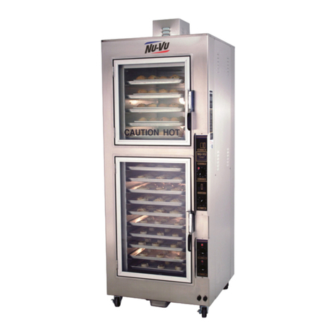
The NU–VU® UB–5/10 Oven compartment can hold five (5) full-size 18"x26" sheet pans and
the Proofer section can hold up to ten (10) full-size 18"x26" sheet pans on the self-contained
Side Racks (no separate wire shelves are required). Measuring 31¼" wide by 34½" deep (with
the Door Handles) and 85½" high the UB–5/10 takes up only 7½ square feet of floor space!
The UB–5/10 is equipped with NU–VU®'s patented positioned air flow system (V–AIR) and
comes with a standard _ hp electric motor coupled to a Blower Wheel to move the heated air
through the Oven compartment in a controlled manner, giving you consistent high-quality
products.

UB–5/10 OWNER'S MANUAL ABOUT YOUR NU–VU® EQUIPMENT
NU–VU® FOOD SERVICE SYSTEMS MENOMINEE, MICHIGAN 49858
(906) 863-4401 SALES FAX (906) 863-5889 • SERVICE FAX (906) 863-6322 page5
The versatilityof the UB–5/10 can be enhanced through the following options:
• COOK–N–HOLD . . . The COOK–N–HOLD system utilizes dual Temperature
Controls and a 24–Hour Timer to bake or cook your product at one temperature and
automatically shift to a lower holding temperature.
• INTERNALLY GENERATED STEAM . . . This system injects a water mist into the
baking chamber where it is flashed into steam. This added steam will provide crusty
breads or rolls for product variations.
• AUTO–MIST . . . This Proofer option eliminates the manually-filled Water Pan in the
Proofer by injecting and distributing a controlled water mist through-out the Proofer
to provide optimum levels of proofing humidity.

NU–VU® EQUIPMENT WARRANTY UB–5/10 OWNER'S MANUAL
NU–VU® FOOD SERVICE SYSTEMS MENOMINEE, MICHIGAN 49858
page 6SALES FAX (906) 863-5889 • SERVICE FAX (906) 863-6322 (906) 863-4401
NU–VU® EQUIPMENT WARRANTY
NU–VU® products are warranted against defects in workmanship and materials. No other
express warranty, written or oral, applies. No person is authorized to give any other warranty
or assume any other liability on behalf of NU–VU®, except by written statement from an
officer of NU–VU®.
Your NU–VU® equipment warranty will begin as soon as your Warranty Registration Card
(attached to the power block or power cord) is received by our Service Department, and is
limited to the following time periods for the original owner only:
PARTS LABOR
Inside the United States 12 Months 12 Months
All areas outside the United States 12 Months 12 Months
These time limits will apply in all cases unless prior arrangements have been made and agreed
to in writing.
The NU–VU® equipment warranty is composed ofthe following:
CONSTRUCTION - -
This warranty covers fabricated metal parts such as side walls, element covers, tops, corner
posts (where used), bases, welded frames and other parts for the lifetime of the unit. The unit is
made from welded stainless steel (or aluminum where applicable) and is warranted to retain the
integrity of the construction during its time of use in the original location of installation. NU–
VU® reserves the right to provide the method of, and person to make, a repair.
PARTS - -
This warranty covers electro-mechanical, mechanical and electronic components including
hinges, latches, thermostats, sensors, thermocouples, heating elements, relays, contactors,
solenoids, power terminal blocks, timers, buzzers, micro switches, motors, motor speed
controls, rocker switches, valves, doors, blower wheels, water pans, and similar components.
Defective parts or components are warranted for the appropriate time period as described
above; starting from the date your Warranty Registration Card is received by NU–VU®.
Replacement parts and components covered by this warranty will ship C.O.D.; customers who
maintain an open account may purchase against their account. The return of defective parts is
required. The return of a defective part or component must be made prior to the issuance of a
credit on an open account. If a part that is returned tests satisfactory in the NU–VU® factory
or at an authorized NU–VU® dealer or service agency, NU–VU® may withhold issuing
credit. Replacement parts will be warranted for a period of ninety (90) days provided they are
installed in a manner authorized by NU–VU®.
The following are excluded from the parts warranty:
• Parts damaged by freight or handling beyond the confines of the NU–VU® factory
• Electrical components (including heating elements) damaged due to improper
installation, or incorrect power supply or wiring

UB–5/10 OWNER'S MANUAL NU–VU® EQUIPMENT WARRANTY
NU–VU® FOOD SERVICE SYSTEMS MENOMINEE, MICHIGAN 49858
(906) 863-4401 SALES FAX (906) 863-5889 • SERVICE FAX (906) 863-6322 page7
• Any part or component deemed defective because of misuse, abuse or failure to
follow procedures listed in the Owner's Manual
• Light bulbs, bulb sockets, fuses and gaskets
• Steam generator elements which fail due to accumulated mineral deposits
• Leaks resulting fromthe removal of sealant in the Oven or Proofer
LABOR - -
We require that you call our NU–VU® Service Department at (906) 863-4401 for service
authorization BEFORE you call any service agency if you wish to claim this expense under the
warranty. We may be able to solve your problem over the telephone, or be able to recommend
one or more capable and reliable service agencies in your area.
This warranty covers the replacement and installation of parts and components which are
included under PARTS for the appropriate time period described on the previous page. This
coverage is limited to the normal mileage allowance for a maximum travel radius of up to fifty
(50) miles, and the normal labor rate times the allowable hours for performing the work as set
forth in the following listing:
NU–VU® FOOD SERVICE SYSTEMS
STANDARD TIME ALLOWANCES FOR WARRANTY REPLACEMENTS
CHANGE PERFORMED CHANGE TIME TEST TIME TOTAL TIME
Oven Motor/Rebalance Fan 1 hr. ½ hr. 1½ hr.
Oven Heating Element 1 hr. ½ hr. 1½ hr.
Control Circuit Board ½ hr. ½ hr. 1 hr.
Control Sensor ½ hr. ½ hr. 1 hr.
Proofer Heating Element ½ hr. ½ hr. 1 hr.
Humidity Element ½ hr. ¼ hr. ¾ hr.
Proofer Motor ½ hr. 5 min. ½ hr.
Change/Adjust Micro Switch ½ hr. 5 min. ½ hr.
Contactor/Relay ½ hr. 5 min. ½ hr.
Timer and/or Buzzer ½ hr. 5 min. ½ hr.
Adjust Door Latch ¼ hr. ¼ hr. ½ hr.
Power Switch ¼ hr. 5 min. ¼ hr.
Indicator Light ¼ hr. 5 min. ¼ hr.
These times are based on servicing a unit that has been installed with allowance made for
access panels on the unit. If the unit is built into a wall that makes servicing very difficult or
impossible without removing part of the counter, wall, trim, etc., the extra time for gaining
access shall be charged to the owner of the unit. NU–VU® has determined that the listed
times, which are based on the period necessary for a trained service person to perform the
work noted, are fair and reasonable. If a problem is not diagnosed within a half hour, the
service person must contact NU–VU®'s Service Department via telephone. The Service
Department is available to assist you Monday through Friday from 7:00 a.m. to 5:00 p.m.
(Central Standard Time). Additional time for problem solving will not be allowed unless this
procedure is followed.

NU–VU® EQUIPMENT WARRANTY UB–5/10 OWNER'S MANUAL
NU–VU® FOOD SERVICE SYSTEMS MENOMINEE, MICHIGAN 49858
page 8SALES FAX (906) 863-5889 • SERVICE FAX (906) 863-6322 (906) 863-4401
An appointment for servicing a unit should be set up since time will not be allowed for waiting
to service a unit. Unless the service person justifies extra time for performing the work noted,
charges for work performed by the service person in excess of the allowed time shall either be
billed to the owner of the equipment or denied.
EXTENDED WARRANTY:
Available at an additional charge. Please ask for a quote depending upon the type of warranty
requested.
WARRANTY LIMITATIONS:
NU–VU®'s warranty for parts and labor is subject to the following limitations:
• NU–VU® will pay for service under warranty if there is a defective component, but
not for:
A service call when the returned part test shows that the part works as per
specification.
Parts or equipment that have been abused, and require replacement or
adjustment.
Calls where the probleminvolves procedures rather than parts or components.
Any overtime charges. NU–VU® will pay straight time only for any work
performed on NU–VU® equipment.
• This warranty will not apply if the unit is moved from the initial place of installation,
unless NU–VU® agrees in writing to continue the warranty after a relocation.
Food service equipment and parts must be installed and maintained in accordance with NU–
VU® instructions. Users are responsible for the suitability of the units or parts to their
application. There is no warranty against damage resulting from accident, abuse, alteration,
misapplication, inadequate storage prior to installation, or improper specification or other
operating conditions beyond our control. Claims against carrier's damage in transit must be
filed by the buyer and, therefore, the buyer must inspect the product immediately upon receipt.
THIS WARRANTY DOES NOT COVER ADJUSTMENTS
DUE TO NORMAL ONGOING USE!
IMPORTANT: NU–VU® WILL NOT PAY FOR ANY SERVICE CALLS AS
WARRANTY WORK IF A NU–VU® AUTHORIZED SERVICE AGENCY
DETERMINES THAT YOUR UNIT IS SET UP AND OPERATING PROPERLY!

UB–5/10 OWNER'S MANUAL NU–VU® EQUIPMENT WARRANTY
NU–VU® FOOD SERVICE SYSTEMS MENOMINEE, MICHIGAN 49858
(906) 863-4401 SALES FAX (906) 863-5889 • SERVICE FAX (906) 863-6322 page9
PARTS RETURN PROCEDURES AND CONDITIONS:
The following procedure shall be followed for the return of parts to the factory for credit
consideration under warranty:
• All parts received by NU–VU® must have a completed Return Authorization Form
as supplied by NU–VU® with the part. Complete and return this Authorization Form
with the defective part(s).
• Parts MUST be packed securely so that in-transit damage cannot occur.
• Prepay shipment. Any parts returned collect will be refused by our Receiving
Department. Credit will be issued on proper returns only.
• As soon as parts are tested and confirmed as defective, credit will be issued against
them.
• If the engineering test shows the component is not defective and in good working
condition, it may be returned to you along with your request for payment.

RECEIPT AND INSTALLATION UB–5/10 OWNER'S MANUAL
NU–VU® FOOD SERVICE SYSTEMS MENOMINEE, MICHIGAN 49858
page 10 SALES FAX (906) 863-5889 • SERVICE FAX (906) 863-6322 (906) 863-4401
RECEIPT AND INSTALLATION
RECEIPT:
It is essential to inspect the unit immediately when it arrives. NU–VU® has placed instructions
on the packaging to help avoid damage in transit. However, an accident or negligent handling
can produce hidden damage. Please follow these steps after receiving your NU–VU® UB–
5/10:
A. Inspect the entire perimeter of the package for damage or punctures to the packing
material. This may indicate damage to the unit inside. Call any and all packing
damage to the attention of the trucker.
B. If any packing damage is found uncrate the unit immediately in the presence of the
delivery person to determine if the unit is damaged. If any damage is found indicate
the type and amount of damage on the shipping documents and notify NU–VU® at
(906) 863-4401 immediately after filing a freight claim.
C. Uncrate the unit carefully and check the entire unit (top and sides) for any visible or
hidden damage.
D. Remove the unit from the shipping pallet and inspect the bottom (including the
Casters) for any damage.
E. If any damage is noted after the driver leaves immediately contact the freight
company and NU–VU® Food Service Systems.
F. Check the Oven and Proofer Doors. Make sure each Door closes completely and that
the Door Gasket seals firmly (refer to the DOOR TEST PROCEDURE in the
SERVICE AND REPLACEMENT GUIDE). If they do not close and seal properly
please contact NU–VU®'s Service Department for instructions and assistance in any
required adjustments.
#1 - Installation

UB–5/10 OWNER'S MANUAL RECEIPT AND INSTALLATION
NU–VU® FOOD SERVICE SYSTEMS MENOMINEE, MICHIGAN 49858
(906) 863-4401 SALES FAX (906) 863-5889 • SERVICE FAX (906) 863-6322 page 11
INSTALLATION PROCEDURES:
Roll the unit into position where it is to be operated. A check should be made to determine that
the power source to be connected is the same voltage and phase as that indicated on the label
on the side of the unit. If the voltage and/or phase is not the same call NU–VU® for
instructions.
Connect your unit according to all applicable local, state and national electrical codes. All
electrical connections must be made with COPPER WIRE ONLY in the correct gauge for the
application. The unit may be connected either with a plug-type connection or through direct
wiring. Allow enough slack in the wiring to allow for equipment to be moved during
installation or anyrequired maintenance or servicing.
The electrician should remove the Side Access Panel on the control side of the unit to expose
the power terminal connections. A wiring schematic for the unit is attached to the wiring near
the Power Terminal Block.
The following steps should be carefully observed:
A. Take note of the labeling on the unit's terminal connections (Line 1, Line 2 and Line
3) at the Power TerminalBlock.
B. Carefully identify the power source connections and attach them to the appropriate
terminals. Make sure all connections are clean and tight.
IMPORTANT: DO NOT ATTACH THE UNIT IF THE POWER SOURCE DOES
NOT COINCIDE WITH THE UNIT LABEL!!!
IMPORTANT: ALL POWER SHOULD BE TURNED OFF AT THE WALL
BREAKER WHILE THE UNIT IS BEING WIRED!!!
#2 - Electrical Connections

RECEIPT AND INSTALLATION UB–5/10 OWNER'S MANUAL
NU–VU® FOOD SERVICE SYSTEMS MENOMINEE, MICHIGAN 49858
page 12 SALES FAX (906) 863-5889 • SERVICE FAX (906) 863-6322 (906) 863-4401
C. Be sure the unit is properly grounded before use by attaching a grounding wire to the
Ground Clamp next to the Power Terminal Block.
D. Carefully set all Switches and Controls on the UB–5/10 to the OFF position and
engage the main power supply.
E. Check the voltage at the connections on the Power Terminal Block with a voltmeter
to confirm conformity with the unit requirements as posted on the side of the unit. If
the voltage readings are correct the unit is ready for its INITIAL START–UP. If the
readings DO NOT coincide you must call NU–VU®'s Service Department for
instructions.
F. Replace the Side Access Panel. Be careful not to pull or pinch any wires while
replacing the Panel.
G. Complete the installation of the optional water supply to the unit and any associated
drain plumbing that may be required (refer to INSTALLATION OF WATER SUPPLY
immediately following).
NOTE: The Proofer compartment of the NU–VU® UB–5/10 is equipped with a
bottom drain. This drain prevents the build-up of excess water that may damage the
Proofer Motor, Humidity or Heating Element, or a Control Sensor. Please install
any locally required drain plumbing at this time. Any required drain plumbing must
be properly installed before attempting an INITIAL START–UP and operational
check. If you choose not to install plumbing from the bottom drain in the Proofer
floor please install the Drain Pan included with your unit. A bracket is provided on
the base of the unit directly beneath the Proofer Door to support the Drain Pan.
H. Push the unit back into place and engage the Caster locks.
INSTALLATION OF OPTIONAL WATER SUPPLY:
IMPORTANT: NU–VU® strongly recommends that SOFT WATER only be used in any unit
requiring a water supply. Also, a good quality water filter MUST be installed in-line between
the unit connection and the water supply to guard against clogging and mineral build-up in the
components. This is extremely important in areas having hard water. The filter may be installed
at the water source or adjacent to the Water Inlet Fitting on the unit, whichever is more
convenient for you.
IMPORTANT: IN ANY 240–VOLT THREE PHASE SYSTEM THE WILD LEG
(240 VOLTS TO NEUTRAL) MUST ALWAYS BE CONNECTED TO L–2!!!
IMPORTANT: IMPROPER INSTALLATION OR OTHER FAILURE TO
FOLLOW THESE INSTRUCTIONS MAY CAUSE SEVERE EQUIPMENT
DAMAGE OR PERSONAL INJURY, AND MAY ALSO VOID ALL OR PART
OF YOUR NU–VU® EQUIPMENT WARRANTY!!!

UB–5/10 OWNER'S MANUAL RECEIPT AND INSTALLATION
NU–VU® FOOD SERVICE SYSTEMS MENOMINEE, MICHIGAN 49858
(906) 863-4401 SALES FAX (906) 863-5889 • SERVICE FAX (906) 863-6322 page 13
Please follow these steps to connect anoptional water supply to your UB–5/10:
A. Run ¼" tubing from the water supply line to the unit location. Allow some slack for
final unit positioning and service. Avoid any kinks or strains on the tubing and place
the tubing where it will not be damaged in any way.
B. The tubing end that attaches to the Oven must not be damaged or deformed in any
way. The cut end should be cut straight and clean with no deforming of the tubing.
All burrs and sharp edges should be removed to ensure a proper and leak-free
connection.
C. Position the tubing so that the tubing runs straight into the Water Intake Fitting. Be
careful not to kink the tubing if you bend it, and do not bend the tubing within two
(2) inches of the end.
D. The two-part compression fitting (tapered collar and nut) is placed approximately 1"
onto the tubing so that the collar is inside of the nut and the threaded opening of the
nut is toward the Water Intake Fitting.
E. Push the tubing all the way into the intake fitting (approximately ¼") and hold it there
while you thread the compression nut onto the Water Intake Fitting. Tighten the
compression nut with an open-end wrench. DO NOT OVER-TIGHTEN!!! If the
joint leaks when tested and further gentle tightening does not stop the leak the two-
part compression fitting must be replaced.
Careful attention to these simple procedures will help to ensure an installation without leaks. If
you have any questions or problems please call NU–VU®'s Service Department at (906) 863-
4401.
IMPORTANT: Please install any required drainage plumbing at this time. Any required
drain line must be properly installed before attempting an INITIAL START–UP and
Operational Check.
IMPORTANT: THIS UNIT NEEDS TO BE INSTALLED WITH ADEQUATE BACKFLOW
PROTECTION TO COMPLY WITH APPLICABLE FEDERAL, STATE AND LOCAL CODES.
IMPORTANT: THIS UNIT REQUIRES A SCREEN OF AT LEAST 100 MESH TO BE
INSTALLED IMMEDIATELY UPSTREAM OF ALL CHECK VALVE TYPE BACKFLOW
PREVENTERS USED FOR WATER SUPPLY PROTECTION. THE SCREEN SHALL BE
ACCESSIBLE AND REMOVABLE FOR CLEANING OR REPLACEMENT.

INITIAL START–UP UB–5/10 OWNER'S MANUAL
NU–VU® FOOD SERVICE SYSTEMS MENOMINEE, MICHIGAN 49858
page 14 SALES FAX (906) 863-5889 • SERVICE FAX (906) 863-6322 (906) 863-4401
INITIAL START–UP
STANDARD OVEN:
A. Make sure any Sidewall Dampers on the Oven Sidewalls
slide freely back and forth. Leave them in the OPEN
position.
B. Remove the glass Light Globes in the rear of the Oven.
Install the included 40-watt Appliance Bulbs and replace the
Light Globes. Close the Oven Door securely. Make sure all
Controls and Switches are in the OFF position.
C. Engage the main electrical supply.
D. Set the Oven Power Switch to ON. The Oven Blower
Wheel should rotate in a counter-clockwise direction when
viewed from the open end.
E. Open the Oven Door. The Oven Motor should come to a
complete stop. Close the Oven Door and let the Motor run
back up to speed.
F. Set the Oven Temperature Control to any desired temperature over 300F. The
Temperature Control Indicator Light should illuminate.
G. Place a quality oven thermometer or test instrument in the center of a baking pan in
the center of the Oven.
H. Check the reading on the thermometer or test instrument against the setting on the
Temperature Control when the Temperature Control Indicator Light goes out. If the
readings differ by more than 10F the Temperature Control may need a simple
adjustment (refer to TEMPERATURE CONTROL, How to Adjust in the SERVICE
AND REPLACEMENT GUIDE). Please call NU–VU®'s Service Department
BEFORE attempting to adjust or recalibrate any Temperature Control!!!
NOTE: Please allow the Temperature Control to cycle two or three times to allow
the Oven temperature to stabilize BEFORE comparing the readings.
I. Set the 60–Minute Oven Timer [24] to 5 minutes and allow it to count down to "0".
The Buzzer Alarm [10] should sound at the end of the timed cycle. If the Buzzer
and/or Timer does not work please call NU-VU®.
WITH COOK–N–HOLD OPTION:
A. Make sure any Sidewall Dampers on the Oven Sidewalls slide freely back and forth.
Leave them in the OPEN position.
B. Remove the glass Light Globes in the rear of the Oven. Install the included 40-watt
Appliance Bulbs and replace the Light Globes. Close the Oven Door securely. Make
sure all Controls and Switches are in the OFF position.
C. Engage the main electrical supply.
#3 - Oven Controls
(Standard)

UB–5/10 OWNER'S MANUAL INITIAL START–UP
NU–VU® FOOD SERVICE SYSTEMS MENOMINEE, MICHIGAN 49858
(906) 863-4401 SALES FAX (906) 863-5889 • SERVICE FAX (906) 863-6322 page 15
D. Set the Oven Power Switch to ON. The Oven
Blower Wheel should rotate in a counter-clockwise
direction when viewed fromthe open end.
E. Open the Oven Door. The Oven Motor should
come to a complete stop. Close the Oven Door and
let the Motor run back up to speed.
F. Make sure the 24–Hour Timer is set to "0" and then
set the Hold Temperature Control to 200. The
Hold Temperature Control Indicator Light should
illuminate.
G. Set the Oven Temperature Control to 300and then
set the 24–Hour Timer to 3 hours or more. The
Oven Temperature Control Indicator Light should
light up as soon as the 24–Hour Timer is moved off
of "0", and the Hold Temperature Control Indicator
Light should go out.
H. Place a quality oven thermometer or test instrument
in the center of a baking pan in the center of the
Oven.
I. Check the reading on the thermometer or test
instrument against the setting on the Temperature
Control when the Temperature Control Indicator
Light goes out. If the readings differ by more than 10F the Temperature Control
may need a simple adjustment (refer to TEMPERATURE CONTROL, How to Adjust
in the SERVICE AND REPLACEMENT GUIDE). Please call NU–VU®'s Service
Department BEFORE attempting to adjust or recalibrate any Temperature Control!!!
NOTE: Please allow the Temperature Control to cycle two or three times to allow
the Oven temperature to stabilize BEFORE comparing the readings.
J. Set the 60–Minute Oven Timer to 5 minutes and allow it to count down to "0". The
Buzzer Alarm should sound at the end of the timed cycle. If the Buzzer and/or Timer
does not work please call NU-VU®.
WITH INTERNAL STEAM OPTION:
A. Make sure any Sidewall Dampers on the Oven Sidewalls slide freely back and forth.
Leave them in the OPEN position.
B. Remove the glass Light Globes in the rear of the Oven. Install the included 40-watt
Appliance Bulbs and replace the Light Globes. Close the Oven Door securely. Make
sure all Controls and Switches are in the OFF position.
C. Engage the main electrical and water supplies.
D. Set the Oven Power Switch to ON. The Oven Blower Wheel should rotate in a
counter-clockwise direction when viewed fromthe open end.
#4 - Oven Controls
(COOK-N-HOLD)

INITIAL START–UP UB–5/10 OWNER'S MANUAL
NU–VU® FOOD SERVICE SYSTEMS MENOMINEE, MICHIGAN 49858
page 16 SALES FAX (906) 863-5889 • SERVICE FAX (906) 863-6322 (906) 863-4401
E. Open the Oven Door. The Oven Motor should come to a
complete stop.
F. Hold down the Micro Switch button in the Hinge-side Door
jamb to start the Motor/Blower Wheel. Press and hold down
the Steam Switch to activate the INTERNAL STEAM option.
The Steam Water Solenoid Valve should give an audible
"click", allowing a water mist to spray from the Injection
Nozzles into the Blower Wheel. Release the Steam Switch at
any time to stop the water spray. Close the Oven Door and let
the Motor run back up to speed.
G. Set the Oven Temperature Control to any desired temperature
over 300F. The Temperature Control Indicator Light should
illuminate.
H. Place a quality oven thermometer or test instrument in the
center of a baking pan in the center of the Oven.
I. Check the reading on the thermometer or test instrument
against the setting on the Temperature Control when the
Temperature Control Indicator Light goes out. If the readings
differ by more than 10F the Temperature Control may need a
simple adjustment (refer to TEMPERATURE CONTROL,
How to Adjust in the SERVICE AND REPLACEMENT
GUIDE). Please call NU–VU®'s Service Department BEFORE attempting to adjust
or recalibrate any Temperature Control!!!
NOTE: Please allow the Temperature Control to cycle two or three times to allow
the Oven temperature to stabilize BEFORE comparing the readings.
J. Set the 60–Minute Oven Timer to 5 minutes and allow it to count down to "0". The
Buzzer Alarm should sound at the end of the timed cycle. If the Buzzer and/or Timer
does not work please refer to the TROUBLE–SHOOTING GUIDE under OVEN - -
"VIII: The Oven Timer does not run" or "IX: The Buzzer does not sound or is not
very loud".
STANDARD PROOFER:
A. Remove the glass Light Globes in the rear of the Proofer. Install the included 40-watt
Appliance Bulbs and replace the glass Light Globes. Close the Proofer Door securely.
B. Set the Proofer Power Switch to ON (this Switch is located on the Oven Control
Panel). The Fan Blade should rotate in a counter-clockwise direction.
C. Set the Proofer Temperature Control to any selected proofing temperature (generally
95-105). The Temperature ControlIndicator Light should illuminate.
D. Place a reliable oven thermometer or test instrument in the center of the Proofer.
#5 - Oven Controls
(INTERNAL STEAM)

UB–5/10 OWNER'S MANUAL INITIAL START–UP
NU–VU® FOOD SERVICE SYSTEMS MENOMINEE, MICHIGAN 49858
(906) 863-4401 SALES FAX (906) 863-5889 • SERVICE FAX (906) 863-6322 page 17
E. Check the reading of the thermometer or test
instrument against the Temperature Control setting
when the Temperature Control Indicator Light goes
out. If the readings differ by more than 10the
Temperature Control may need a simple adjustment
(refer to TEMPERATURE CONTROL, How to
Adjust in the SERVICE AND REPLACEMENT
GUIDE). Please call NU–VU®'s Service
Department BEFORE attempting to adjust or
recalibrate any Temperature Control!!!
NOTE: Please allow the Temperature Control to
cycle two or three times to allow the temperature to
stabilize BEFORE comparing the readings.
F. Remove the Water Pan. Set the Proofer Humidity
Control to #5 or #6. The Humidity Control
Indicator Light should light up and the round Humidity Element willbegin to heat up.
G. Fill the Water Pan with approximately 2" of water and place it on the Humidity
Element. Close the Proofer Door securely. The water should begin to heat up
(bubbles will form on the bottom) and in a few minutes a light fogging will begin to
form on the Proofer Door glass.
H. Return all Switches and Controls to their OFF positions.
AUTO–MIST PROOFER: (refer to Illustration #7 above)
A. Remove the glass Light Globes in the rear of the Proofer. Install the 40-watt
Appliance Bulbs and replace the glass Light Globes. Leave the Proofer Door open.
B. Set the Proofer Power Switch to ON (this Switch is located on the Oven Control
Panel). The Blower Wheel should rotate in a counter-clockwise direction.
C. Set the Humidity Control to #9 or #10. The HumidityControl Indicator Light should
illuminate and a light water mist will be sprayed from the Injection Nozzle into the
Proofer Blower Wheel. In a second or two the spraywill stop and the Indicator Light
will go out. After a short pause the Humidity Control will cycle again.
NOTE: The AUTO–MIST option controls the humidity in the Proofer by using a
solid-state Repeat Cycle Timer. This Timer has a fixed "OFF" time of 45 seconds
and an adjustable "ON" time from 0.2 to 2.0 seconds. Changing the setting of the
Humidity Control varies the "ON" time and thus regulates the duration of the water
spray in the Proofer.
D. Close the Proofer Door. Set the Proofer Temperature Control to any selected
proofing temperature (generally 95-105). The Temperature Control Indicator Light
should illuminate.
#6 - Proofer Controls

INITIAL START–UP UB–5/10 OWNER'S MANUAL
NU–VU® FOOD SERVICE SYSTEMS MENOMINEE, MICHIGAN 49858
page 18 SALES FAX (906) 863-5889 • SERVICE FAX (906) 863-6322 (906) 863-4401
E. Place a reliable oven thermometer or other test instrument in the center of the
Proofer.
F. Check the reading of the thermometer or test instrument against the Temperature
Control setting when the Temperature Control Indicator Light goes out. If the
readings differ by more than 10the Temperature Control may need a simple
adjustment (refer to TEMPERATURE CONTROL, How to Adjust in the SERVICE
AND REPLACEMENT GUIDE). Please call NU–VU®'s Service Department
BEFORE attempting to adjust or recalibrate any Temperature Control!!!
NOTE: Please allow the Temperature Control to cycle two or three times to allow
the temperature to stabilize BEFORE comparing the readings.
Other manuals for UB 5/10
1
Table of contents
Other NUVU Commercial Food Equipment manuals
Popular Commercial Food Equipment manuals by other brands

Rational
Rational iCombi Pro Original installation manual

Prince Castle
Prince Castle FLAME KING BROILER Install & Operation Manual

Royal Catering
Royal Catering RCFW-110D-PRO user manual

JAC
JAC DIV Translation of original user instructions

Memmert
Memmert WTB 50 operating manual

Equipex
Equipex SODIR RBE-25 Operation manual