nvent WCHE Series User manual

© 2018 nVent 89087984
Rev. J P/N 89087983
Air-To-WATer HeAT excHAngers
WcHe Models
INSTRUCTION MANUAL

© 2018 nVent 89087984
- 2 -
NOTE: Please read this manual carefully before installing the unit. This user manual is an
integral part of the product and should accompany it until it is eventually disassembled.
TABLE OF CONTENTS
HOW TO CONSULT THIS MANUAL ........................................................................................................................................................... 2
THIS MANUAL IS INTENDED FOR THE FOLLOWING:............................................................................................................................................... 3
PURPOSE OF THE INFORMATION CONTAINED IN THIS MANUAL:........................................................................................................................ 3
RESTRICTIONS TO THE USE OF THIS MANUAL....................................................................................................................................................... 3
WHERE AND HOW TO STORE THIS MANUAL........................................................................................................................................................... 3
CURRENT TECHNOLOGY ............................................................................................................................................................................................ 3
UPDATES ...................................................................................................................................................................................................................... 3
IN THE EVENT OF SALE OF THE PRODUCT .............................................................................................................................................................. 3
UNPACKING AND INSPECTION................................................................................................................................................................. 4
Included in the carton:................................................................................................................................................................................................. 4
UNIT IDENTIFICATION................................................................................................................................................................................................. 4
SAFETY REMARKS ..................................................................................................................................................................................... 5
PRECAUTIONS WHEN HANDLING THE UNIT ........................................................................................................................................................... 5
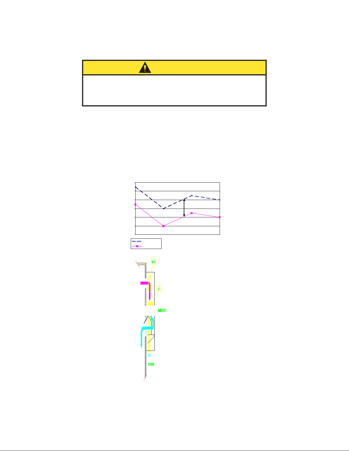
OPERATING PRINCIPLE ............................................................................................................................................................................. 6
COOLING CAPACITY.................................................................................................................................................................................................... 7
Performance Data WCHE019 Series.......................................................................................................................................................................... 7
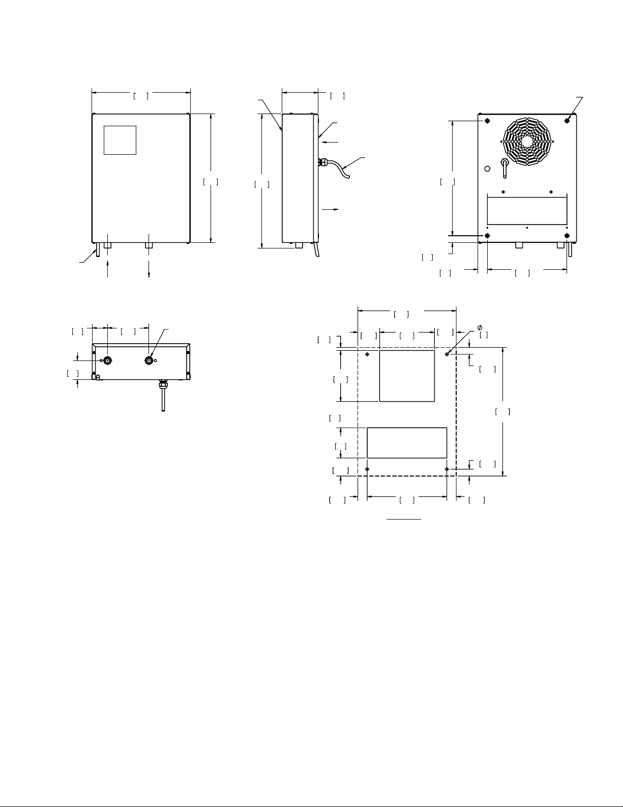
Design Data WCHE019 Series................................................................................................................................................................... 8
Performance Data WCHE049 Series.......................................................................................................................................................................... 9
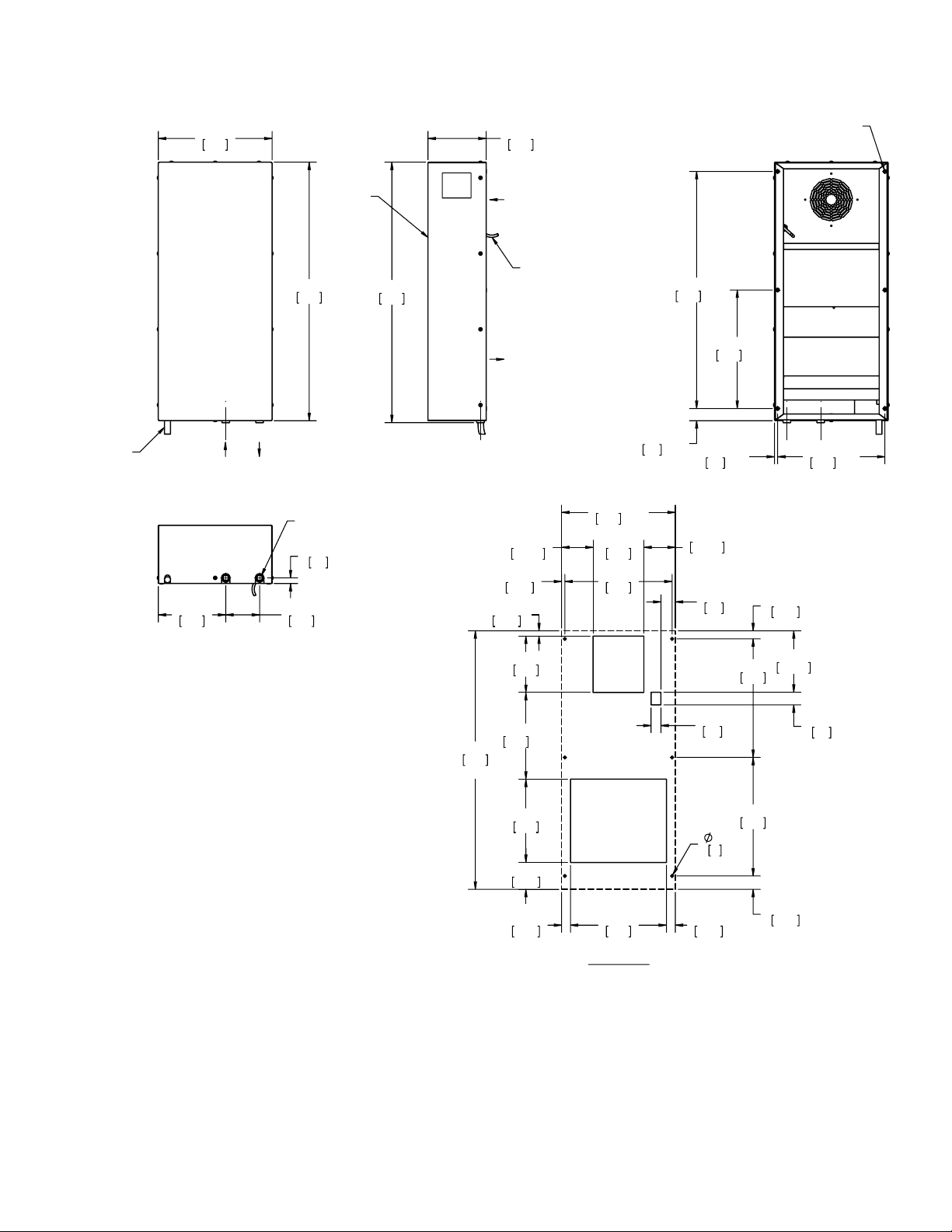
Design Data WCHE049 Series.................................................................................................................................................................10
Performance Data WCHE069 Series........................................................................................................................................................................ 11
Design Data WCHE069 Series.................................................................................................................................................................12
Performance Data WCHE149 Series........................................................................................................................................................................ 13
Design Data WCHE149 Series.................................................................................................................................................................14
INSTALLATION INSTRUCTIONS..............................................................................................................................................................15
Installation.................................................................................................................................................................................................................. 15
WATER CONNECTIONS.............................................................................................................................................................................................16
MECHANICAL PARTS...............................................................................................................................................................................18
STRUCTURE................................................................................................................................................................................................................18
HEAT EXCHANGE BANK ...........................................................................................................................................................................................18
CONDENSATE COLLECTION BASIN.........................................................................................................................................................................18
FLOW CONTROL SOLENOID VALVE.........................................................................................................................................................................18
MOTORS .................................................................................................................................................................................................... 19
FANS............................................................................................................................................................................................................................ 19
CONTROL, MONITORING AND SAFETY COMPONENTS ......................................................................................................................19
REGULATING THERMOSTAT FOR SOLENOID VALVE.............................................................................................................................................19
Adjustments.......................................................................................................................................................................................... 19
ELECTRICAL CONNECTIONS ..................................................................................................................................................................20
WCHE019 only ........................................................................................................................................................................................................... 20
WCHE049, WCHE069, WCHE149 ............................................................................................................................................................................. 21
START-UP................................................................................................................................................................................................... 21
TEMPERATURE CONTROL.......................................................................................................................................................................21
PRELIMINARY CHECKS AFTER STARTING THE UNIT ..........................................................................................................................21
TURNING OFF THE UNIT.......................................................................................................................................................................... 21
MAINTENANCE......................................................................................................................................................................................... 22
PREVENTATIVE MAINTENANCE SCHEDULE..........................................................................................................................................................22
Twice a year .......................................................................................................................................................................................... 22
Annually................................................................................................................................................................................................. 22
REPLACEMENT OF COMPONENTS.................................................................................................................................................... 22
HOW TO CLEAN THE UNIT .................................................................................................................................................................. 22
INACTIVITY ........................................................................................................................................................................................... 22
INFORMATION ON RESIDUAL HAZARDS AND EMERGENCY SITUATIONS ........................................................................................23
GENERAL SAFETY PROVISIONS ......................................................................................................................................................... 23
HAZARDS ARISING FROM THE PRODUCT COMING INTO CONTACT WITH THINGS OR PERSONS.................................................................23
SAFETY STANDARDS FOR ELECTRICAL EQUIPMENT...........................................................................................................................................23
Introduction........................................................................................................................................................................................... 23
TASKS ASSIGNED TO OFFICERS-IN-CHARGE.........................................................................................................................................................23
HIGH VOLTAGE...........................................................................................................................................................................................................23
SAFETY STANDARDS TO COMPLY WITH WHEN THE EQUIPMENT IS TURNED OFF .........................................................................................24
SAFETY STANDARDS TO COMPLY WITH WHEN SERVICING LIVE EQUIPMENT ................................................................................................24
SAFETY STANDARDS TO COMPLY WITH WHEN SERVICING THE UNIT..............................................................................................................24
FIRE HAZARDS...........................................................................................................................................................................................................24
TOXIC SUBSTANCES .................................................................................................................................................................................................24
DANGERS ARISING FROM FLUIDS........................................................................................................................................................................... 24
DISASSEMBLING THE UNIT.....................................................................................................................................................................25
TROUBLE SHOOTING ...............................................................................................................................................................................26
Symptoms and Possible Causes:............................................................................................................................................................................. 26
Replacement Parts .................................................................................................................................................................................................... 27
WARRANTY ............................................................................................................................................................................................... 30
RETURN AND REPAIR POLICY.................................................................................................................................................................................. 30
LIMITATION OF LIABILITY......................................................................................................................................................................................... 31

© 2018 nVent
89087984 - 3 -
HOW TO CONSULT THIS MANUAL
This document contains general information applicable to all models. In the event of any information updates
becoming necessary, such updates shall be inserted in the enclosures.
THIS MANUAL IS INTENDED FOR THE FOLLOWING:
• Owner of the appliance
• Person responsible for its installation
• Person responsible for managing the product
• Person responsible for ordinary maintenance
• Person responsible for its disassembly
PURPOSE OF THE INFORMATION CONTAINED IN THIS MANUAL:
• CORRECT HANDLING: performed by unskilled personnel
• CORRECT INSTALLATION: performed by skilled personnel
• CORRECT MANAGEMENT: performed by skilled personnel
• CORRECT MAINTENANCE: performed by skilled personnel
• CORRECT ORDER FOR SPARE PARTS: CORRECT DISPOSAL OF THE PRODUCT: made by skilled personnel
RESTRICTIONS TO THE USE OF THIS MANUAL
They apply to any operations that must be performed by highly skilled personnel.
WHERE AND HOW TO STORE THIS MANUAL
Inside the electric cabinet or together with any other literature concerning the equipment which utilizes
the product, provided it is a dry and clean place.
In the event of the manual being misplaced or damaged, the customer may require, for a fee, a new
manual, by quoting the model and serial number shown on the technical name- plate, by contacting:
P8GPV
*QHHOCP9
C[
#
PQMC/075#
P8GPVEQO
CURRENT TECHNOLOGY
Thismanualreectsthestateoftheartexistingatthetimetheproductismarketedandshallnot
be deemed to be inadequate for the sole reason that it has not been updated as a result of any new
experience.
UPDATES
nVent Equipment Protection reserves the right to update the product and relevant manual without being
requiredtoupdatepreviousproductsandmanualsotherthaninexceptionalcircumstances.Torequireor
receive any updates of the instructions manual or amendments thereto, which shall be deemed to be an
integral part of the manual, please contact nVent Equipment Protection.
Any suggestions or recommendations made by installers or users of the product for the purpose of
improving the product or the contents of this manual, will be greatly appreciated by the Manufacturer.
IN THE EVENT OF SALE OF THE PRODUCT
Please advise nVent Equipment Protection of the address of the new owner so as to enable the dispatch
of any updates to the manual, otherwise nVent Equipment Protection shall be relieved of any subsequent
liabilities.

© 2018 nVent 89087984
- 4 -
UNPACKING AND INSPECTION
Hoffman®coolingbrandedproductsareshippedex-works.Allunitshavebeenindividuallyinspectedandcarefully
packaged.
Immediately inspect the unit upon receipt, making sure it has been shipped in its proper position. Note improper
shipment on the shipping document. We recommend accepting merchandise subject to inspection.
Check for damage and, if any, note this immediately on the shipping document.
Removepackingandcheckthattheexteriorcasingisnotscratched,markedorhavesignsofblowsandthatno
components are missing.
Before throwing the packaging away, check that it does not contain documents or additional parts of the unit.
Any damage that is encountered must be communicated to the carrier by registered letter within 8 days of
receipt.
The carrier is responsible for any damage caused during shipment.
nVent Equipment Protection is not responsible for damage caused to the merchandise by the shipper but will do
all in its power to assist customers in these situations.
INCLUDED IN THE CARTON:
• HeatExchanger
• Mounting fastener kit
• Mounting gasket
• G-NPT Adapting Valves (2)
• User Manual
NOTE: This product may not be returned without prior written approval by nVent Equipment
Protection.
NOTE: If installation of the product is not immediately required or the product needs to be
transported to its final destination, repackage it after your initial inspection, and store it in a
safe place.
UNIT IDENTIFICATION
Thisunitcanbecorrectlyidentiedbythetechnicalnameplatecontainingalltheinformationforits
correct use.
Thetechnicalname-plateisembossedonaplasticsupportwhichensureshighenduranceofthetext
eveninparticularlydicultenvironments.
Note: The serial number is required for any assistance or information concerning the unit
described in this manual.

© 2018 nVent
89087984 - 5 -
SAFETY REMARKS
Operationandmaintenanceoftheheatexchangerscanbedangerousifnotcarriedoutwiththesamecareas
giventootherappliancesthathavemovingpartsandelectriccomponentsnexttowater.
Onlyskilledpersonnelmayrepair,inspectormaintaintheheatexchangers.
Before servicing this unit, refer to the instructions contained in this manual, check the data on the name-plate and
follow any other precaution to ensure absolute safety.
Disconnect power before working on the unit.
WARNING
PRECAUTIONS WHEN HANDLING THE UNIT
Metal edges may be sharp. Be careful handling the unit, and always wear gloves.

© 2018 nVent 89087984
- 6 -
OPERATING PRINCIPLE
Hoffmancoolingbrandedair-to-waterheatexchangersaredesignedforcoolingelectriccabinetswith
either a Type 12 or IP55 protection and are suitable for operating in industrial environments. These
models eliminate problems caused by high temperatures of the cabinet and prevent dirt and dust from
penetrating inside the electric board.
It is required that the water temperature be lower than the cabinet
temperaturefortheair-to-waterheatexchangertoworkproperly.
CAUTION
Coolingwater,aconstantowofwhichmustbefurnishedbytheuseratatemperaturethatislowerthanthe
temperatureinthecabinet,passesthroughthetubesinaheatexchangerwithcoppertubesandaluminumns
and back into the cabinet.
Heatistransferredthroughthewallsofthecoppertubes,exchangingheatfromthenstothecoldwatersothat
theairexitscoolerandthewaterhotter.
Note: The greater the difference between these two temperatures the more heat is exchanged.
Tem perature trend
0
10
20
30
40
50
60
tim e
°C
internal temp.
w ater temp.
t
AMBIENT
CA BI NET
WATER

© 2018 nVent
89087984 - 7 -
COOLING CAPACITY
Thisdependsonthespecicexchangefactoroftheheatexchanger(indicatedonthelabel)andthe
temperature difference between the interior of the cabinet and the cooling water.
FOR EXAMPLE:
Model: WCHE04916
Capacitynotedonlabel:2200W@25C∆T
Specicheattransmission:2200/25=88W/°C
Application:
Maximuminternalcabinettemperaturedesired:40C
Maximumestimatedwatertemperature:20C
∆TDifference:20C
Coolingcapacity:88x20=1760W
PERFORMANCE DATA WCHE019 SERIES
Parameter Units WCHE01916002 WCHE01926002
Voltage / Phase / Frequency V/ph/Hz 115/1/50-60 230/1/50-60
CoolingcapacityL35W10(25°CdT) W870
Power absorbed W28
Current absorbed A0.5
Maxairowthroughheatexchanger CFM (m3/h) 118 (200)
Recommendedwaterow gpm (l/h) 0.66 (150)
Pressure drop at recommended water
ow psi (kPa) 0.3 (2)
Maxwaterpressure psi (kPa) 73 (500)
Water connections (using valves) NPT 3/8 inch
OperatingtemperatureMin/Max °F(°C) 50/122 (10/50)
Noise level (measured at 1m) dB(A) 58
Duty cycle %100
Protective system side cabinet Type 12 / IP55
Protective system side ambient IP55
Weight lb (kg) 20 (9)
Electrical connection 6 foot (1.8m) cord with
NEMA 5-15P 6 foot (1.8m) cord with
NEMA 6-15P

© 2018 nVent 89087984
- 8 -
DESIGN DATA WCHE019 SERIES
:$7(5
,1
:$7(5
287
&21'(16$7(
'5$,178%(
(1&/2685(
$,5,1
(1&/2685(
$,5287
)5217
%$&.
)705()
32:(5&25':,7+3/8*
002817,1*+2/(6
%633*)(0$/(
:$7(5&211(&7,21
NOTES:
1. "G" TO NPT ADAPTING VALVES ARE INCLUDED
AND SHIPPED WITH THE UNIT.
5()
5()
5()
5()
&87287
89090291

© 2018 nVent
89087984 - 9 -
PERFORMANCE DATA WCHE049 SERIES
Parameter Units WCHE04916002 WCHE04926002
Voltage / Phase / Frequency V/ph/Hz 115/1/50-60 230/1/50-60
CoolingcapacityL35W10(25°CdT) W2200
Power absorbed W90
Current absorbed A0.8
Maxairowthroughheatexchanger CFM (m3/h) 247 (420)
Recommendedwaterow gpm (l/h) 0.66 (150)
Pressure drop at recommended water
ow psi (kPa) 4.4 (30)
Maxwaterpressure psi (kPa) 145 (1000)
Water connections (using valves) NPT 1/2 inch
OperatingtemperatureMin/Max °F(°C) 50/122 (10/50)
Noise level (measured at 1m) dB(A) 58
Protective system side cabinet Type 12 / IP55
Protective system side ambient IP55
Duty cycle %100
Weight lb (kg) 44 (20)
Electrical connection 6 foot (1.8m) cord with
NEMA 5-15P 6 foot (1.8m) cord with
NEMA 6-15P

© 2018 nVent 89087984
- 10 -
DESIGN DATA WCHE049 SERIES
:$7(5
,1
:$7(5
287
&21'(16$7(
'5$,178%(
(1&/2685(
$,5,1
(1&/2685(
$,5287
)5217
)705()
32:(5&25':,7+3/8*
002817,1*+2/(6
%633*)(0$/(
:$7(5&211(&7,21
NOTES:
1. "G" TO NPT ADAPTING VALVES ARE INCLUDED
AND SHIPPED WITH THE UNIT.
5()
5()
5()
5()
5()
&87287
89090292

© 2018 nVent
89087984 - 11 -
PERFORMANCE DATA WCHE069 SERIES
Parameter Units WCHE06916002 WCHE06926002
Voltage / Phase / Frequency V/ph/Hz 115/1/50-60 230/1/50-60
CoolingcapacityL35W10(25°CdT) W3100
Power absorbed W115
Current absorbed A 1
Maxairowthroughheatexchanger CFM
(m3/h) 265 (450)
Recommendedwaterow gpm (l/h) 2.2 (500)
Pressuredropatrecommendedwaterow psi (kPa) 9.1 (63)
Maxwaterpressure psi (kPa) 145 (1000)
Water connections (using valves) NPT 1/2 inch
OperatingtemperatureMin/Max °F(°C) 50/122 (10/50)
Noise level (measured at 1m) dB(A) 58
Protective system side cabinet Type 12 / IP55
Protective system side ambient IP55
Duty cycle %100
Weight lb (kg) 46 (21)
Electrical connection 6 foot (1.8m) cord with
NEMA 5-15P 6 foot (1.8m) cord with
NEMA 6-15P

© 2018 nVent 89087984
- 12 -
DESIGN DATA WCHE069 SERIES
:$7(5
,1
:$7(5
287
&21'(16$7(
'5$,178%(
(1&/2685(
$,5,1
(1&/2685(
$,5287
)5217
)705()
32:(5&25':,7+3/8*
002817,1*+2/(6
%633*)(0$/(
:$7(5&211(&7,21
NOTES:
1. "G" TO NPT ADAPTING VALVES ARE INCLUDED
AND SHIPPED WITH THE UNIT.
5()
5()
5()
5()
5()
&87287
89090293

© 2018 nVent
89087984 - 13 -
PERFORMANCE DATA WCHE149 SERIES
Parameter Units WCHE14916002 WCHE14926002
Voltage / Phase / Frequency V/ph/Hz 115/1/50-60 230/1/50-60
CoolingcapacityL35W10(25°CdT) W6700
Power absorbed W200 245
Current absorbed A 2 1.3
Maxairowthroughheatexchanger CFM (m3/h) 500 (850)
Recommendedwaterow gpm (l/h) 3.8 (860)
Pressuredropatrecommendedwaterow psi (kPa) 5.8 (40)
Maxwaterpressure psi (kPa) 145 (1000)
Water connections (using valves) NPT 1/2 inch
OperatingtemperatureMin/Max °F(°C) 50/122 (10/50)
Noise level (measured at 1m) dB(A) 58
Protective system side cabinet Type 12 / IP55
Protective system side ambient IP55
Duty cycle %100
Weight lb (kg) 86 (39)
Electrical connection 6 foot (1.8m) cord with
NEMA 5-15P 6 foot (1.8m) cord with
NEMA 6-15P

© 2018 nVent 89087984
- 14 -
DESIGN DATA WCHE149 SERIES
&21'(16$7(
'5$,178%(
:$7(5
,1
:$7(5
287
(1&/2685(
$,5,1
(1&/2685(
$,5287
)5217
)705()
32:(5&25':,7+3/8*
002817,1*+2/(6
%633*)(0$/(
:$7(5&211(&7,21
NOTES:
1. "G" TO NPT ADAPTING VALVES ARE INCLUDED
AND SHIPPED WITH THE UNIT.
5()
5()
5()
5()
5()
5()
&87287
89090294

© 2018 nVent
89087984 - 15 -
INSTALLATION INSTRUCTIONS
Before installing, check the following:
• The cabinet is Type 12 or IP55 type, depending on the overall rating required
• There is enough room for an easy application and installation, both inside and outside the cabinet
• The cabinet is clean on the inside
• Thecabinetisnotinthevicinityofheatsourcesorwarmairows
• The inside of the cabinet allows a proper air circulation, preventing any recirculation
• There is enough clearance to remove the outer cover and access the components.
For wall-mount applications, the following safety instructions must be complied with:
• Theheatexchangermustbeinstalledashighaspossible
• If it is installed on a door, make sure that the hinges are strong enough to support the unit
• Make sure that the electric cable does not get torn or damaged with the door closed
• Ifthedepthoftheheatexchangerblockstheentiredooropeningclearance,provideadoorstopforit
• Cabinetpanelmustbeatandrigidtoformatightsealwiththemountinggasket.
INSTALLATION
NOTE: Prior to drilling holes or making cuts on the cabinet, make sure that holes, screws,
cables, etc. do not interfere with the equipment which has already been installed.
1. Identify the proper cutout drawing for the model being installed. Paper templates (included with
the unit) are marked with EXW## designations. The cross reference below indicates the template
for each model. Cutout drawings are also shown in this manual.
Model Template Marking
WCHE019 EXW06
WCHE049 EXW15
WCHE069 EXW25
WCHE149 EXW50
2. Make cuts on the cabinet panels by following the relevant template. Remove any chips, burrs or
sharp edges.
3. Attachtheadhesivegasket(included)tothemountingsurfaceoftheheatexchangerasshown.
4. Placetheheatexchangeragainstthecabinetandsecureitwiththeappropriatescrews(included).
Verify cabinet panel forms a tight seal with the mounting gasket.
3/$&(*$6.(76
+(5(
29(5/$3%27720*$6.(7
,16,'(723*$6.(7PP
3/$&(*$6.(76+(5(
29(5/$3*$6.(76PP
),(/'$33/,&$7,212)02817,1**$6.(7
WCHE019 ONLY ALL OTHER MODELS
89086208
89087063

© 2018 nVent 89087984
- 16 -
WATER CONNECTIONS
1. Make plumbing connections using the on/off valves included. Use thread tape on the valve
threads when making these connections. The connections on the unit are ‘G’ thread. ‘G’ to NPT
adaptingvalvesareincluded.DonotconnectNPTttingsdirectlytotheheatexchanger,asthe
threads are not compatible and the connection will leak.
Note: Once unit is connected to water, PROTECT THE UNIT FROM FREEZING. Even after it is
disconnected, the heat exchanger will hold water and could be severely damaged by freezing
temperatures.
2. Makesurethepressureintheplumbingcircuitdoesnotexceedadmissiblevalues.
3. Introduce water into the circuit, making sure there are no leaks from pipelines.
4. Install an inlet and an outlet pressure gauge on the plumbing circuit plus a gate valve.
5. Thiswillpermityoutocontrolthespeedofthewaterinsidetheheatexchangecoilandavoid
dangerous corrosion of the copper piping.
6. This is done by adjusting the gate valve so that the pressure gauges show a pressure difference
thatisapproximatelyequaltothestatedloadlosses.
Note: If the unit contains a solenoid valve, it will allow flow of water only when the unit is
powered and calling for cooling.
For example: WCHE06916 stated pressure drop: 9.1 psi. The difference between inlet-
pressure value and out-pressure value ~9 psi.
WATER
IN
WATER
OUT
CONDENSATE
DRAIN TUBE
2X "G" MALE TO NPT FEMALE ADAPTING
VALVE (INCLUDED AND SHIPPED WITH UNIT)
BSPP (G) FEMALE
WATER CONNECTION (2)
2X PRESSURE GAUGE (CUSTOMER SUPPLIED)
GATE VALVE (CUSTOMER SUPPLIED)

© 2018 nVent
89087984 - 17 -
7. Forcorrectuseoftheheatexchangerandtoavoidcorrosion,thewaterusedfortheheat
exchangermusthavehydrologicalvaluesaslisted:
Chemical parameters of the circuit water
Characteristic Parameter
Langelierindex -0.2 < L < +0.4
Chloride ions [Cl-] < 10 mg/l (ppm)
Sulfate ions [SO4 2-] < 30 mg/l (ppm)
Nitrates and nitrites[NO3-] < 30 mg/l (ppm)
Iron < 0.5 mg/l (ppm)
Cooper < 0.5 mg/l (ppm)
Resistivity 2000 < R < 5000 Ohm cm
pH value 6.9 < pH < 8
Alkalinity [HCO] < 300 mg/l (ppm)
[Ca2+ , Mg2+] / [HCO3-] > 0.5
Oxygen 4 < [O2] < 9 mg/l (ppm)
[CO2] < 30 mg/l (ppm)
Failure to comply with these instructions, in addition to
compromising proper machine operation, causes cancellation of
guarantee coverage.
CAUTION

© 2018 nVent 89087984
- 18 -
MECHANICAL PARTS
STRUCTURE
Made with self-supporting sheet metal panels, passivated and with primer coat to ensure good resistance
to corrosion, easily inspected and at the same time giving suitable protection to internal components.
Components inside the structure are only accessible by removing the front cover. This is done by
removing screws using appropriate tools.
HEAT EXCHANGE BANK
Thisiswhereheatexchangetakesplacebetweencabinetairandcoolingwater.Itiscomposedofcopper
pipeswithaluminumns.
CONDENSATE COLLECTION BASIN
This is built into the unit’s frame and is made of galvanized sheet or stainless steel. It comes standard
withacondensatedrainpipethatexitsfromtheheatexchanger.
ambi ent
cabi net
FLOW CONTROL SOLENOID VALVE
This is a normally-closed two-way type (ON/OFF).
Controlledbyaninternalthermostat,thisvalveopenstheowofwaterwhenthepresettemperatureis
reached.Itstopstheowwhencoolingisnolongerneeded,orwhenpowerisdisconnectedfromtheunit.

© 2018 nVent
89087984 - 19 -
MOTORS
FANS
Fans run full speed to constantly circulate enclosure air, they are not controlled by the thermostat.
These may be of different types depending on the model. They are either:
-multi-bladeaxial,withoutsiderotoronbearings,dynamicallybalanced.
-compactaxial,onbearings
- radial, with plastic or metal rotor, on bearings
These fans are manufactured in accordance with Standard EN 60 335 1. They are treated with rust-
inhibiting plastic materials, with class B insulation and class 1 protection.
The motor protection is IP44, in accordance with Standard DIN40500 whereas the safety degree complies
with Standards DIN30110.
Noise levels are consistent with Standard DIN 45635.
CONTROL, MONITORING AND SAFETY COMPONENTS
REGULATING THERMOSTAT FOR SOLENOID VALVE
Thisisagas-loadedmechanicalthermostat.Itmeasurestheairtemperatureenteringtheheatexchanger,
anduponreachingthesetpoint,activatesthesolenoidvalvetoopentheowofcoolingwater.
In some models the mechanical thermostat may be replaced with an electronic thermostat, whose
specicationsareoutlinedinthesupplementstothemanual.
ADJUSTMENTS
Toadjustthethermostatsetting,rstinterruptpowertotheunit.Removetheheatexchanger’s
front cover to access the thermostat.
The thermostat is set at 35 C (95 F) at the factory. It can be adjusted using a screwdriver to turn
its pin. The thermostat can be set to temperatures from 20 C to 46 C (68 F to 115 F). Contact our
service department for temperatures other than those in the pre-set range.
Note: The thermostat has a 4 C (7 F) hysteresis, therefore the solenoid valve will open at a
temperature 4 C (7 F) greater than the set temperature.
Temperature Conversion
°C °F
20 68
25 77
30 86
35 95
40 104
45 113
After making the adjustment, replace the front cover and resupply voltage.

© 2018 nVent 89087984
- 20 -
ELECTRICAL CONNECTIONS
Check supply voltage before making any connections. Supply
voltagemustbeasspeciedontheunit’snameplate.
WARNING
Connectthepowercordtoaproperlygroundedpowersource.Useofanextensioncordisnotrecommended.
Electrical connections must be made according to local applicable codes and standards.
An automatic circuit breaker with a capacity as indicated on the
unit’s nameplate must be installed.
WARNING
WCHE019 ONLY
32:(5
&25'
*51<(/
%/8
%/.
%51
%/.
%/.
%/.
&
)$1
767$7
62/(12,'
9$/9(
%/.
%/.
*51<(/
:,5(',$*5$0
89086208
This manual suits for next models
12
Table of contents
Popular Heat Pump manuals by other brands

LG
LG LC098HV4 Engineering manual

Mitsubishi Electric
Mitsubishi Electric PUZ-WM AA Series installation manual

Regulus
Regulus RTC 20e Installation and maintenance manual

Gemas
Gemas FASHCW Installation instructions manual

Heat Controller
Heat Controller DMH18DB-1 Service manual

Zodiac
Zodiac ZS500 Instructions for installation and use