nvent CADDY Speed Link SLS Series Release Note

TECHNICAL HANDBOOK
nVent CADDY Speed Link Manual
SLS Locking Device

1. WIRE ROPE SUPPORT OVERVIEW 3
A. Using Wire Rope 3
B. The nVent CADDY Speed Link Manual 3
C. SLS Features 4
D. SLS Mechanism 5
2. TYPICAL SPEED LINK SLS INSTALLATION 6
A. Installation Procedure 6
B. Compatible Channels 7
3. THE SPEED LINK ADVANTAGE 8
A. CADDY Speed Link SLS End-Fittings 8
B. Installation Angle 9
C. Common Applications 10
4. SPEED LINK CERTIFICATE AND LISTINGS 11
5. ADDITIONAL WARNINGS AND SAFETY INSTRUCTIONS 11
Contents
2 |nVent.com/CADDY

nVent.com/CADDY |3
1. Wire Rope Support Overview
A. USING WIRE ROPE
Wire rope support systems are beneficial because they are flexible, adaptable, and lightweight. The Speed Link Universal Support
System offers an extensive line of products designed to be the most effective wire rope support solution on the market. However,
inorder to reap the unique benefits of the system, it is important to select the correct locking device and end fitting for anyproject.
Speed Link has two locking devices for 2 mm and 3 mm wire: the SLK and the SLS. The SLS is a single-barreled locking device
that is best suited for strut, C-channel, signage, and HVAC units. The system can be attached at structure with one of four end-fittings,
and connected to the load with the locking device.
B. THE NVENT CADDY SPEED LINK MANUAL
In this document, you will find the different solutions Speed Link has to offer and the best method for installation for each type of cable
management system as well as a detailed breakdown of unique benefits associated with each method, images, diagrams and a basic
step-by-step installation process.
This document is one part of a series of Speed Link Manuals designed around specific products and applications. Although this
document focuses specifically on the Speed Link SLS System, several other resources are available under the “Documents” tab
on a Speed Link product page on nVent.com/CADDY. The documents are always being updated, and new sections are continuously
being released.
For more information on specific products or view the other sections of the Speed Link Manual, visit nVent.com/CADDY.

4 |nVent.com/CADDY
1. Wire Rope Support Overview
C. SLS FEATURES
The locking device is the piece of hardware that holds the wire loop in place. The Speed Link SLS locking device is designed to be the
safest, most aesthetical, and easiest locking device on the market. The guide below shows several of the product’s innovative features
and the overall goal of each one.
EASE OF USE FEATURES
Push-to-install retaining
nut simplifies installation
Engineered elongated retaining
nut reduces unwanted sway
ofthetrapeze during installation
andprovides higher stability
The outside of the housing
isthreaded for easy and secure
attachment to the nut
Speed Link is lighter, faster to install,
easier to transport and generates
less waste than alternative
hangingmethods
Two tool-free locking devices are
available for three wire sizes
• SLS2 compatible with
1.5mm and 2mm wire
• SLS3 compatible with
3mm wire
SAFETY FEATURES
Length of stem allows the device
to be installed in strut profiles
without the need to insert fingers
ortools into the strut
UL Listing on all 4 end-fittings
for pre-cut lengths
2-jaw gripping mechanism
is designed for stronger grip,
limiting the possibility of
accidentally dropping the load
Keyless release tube is designed
to allow safe and easy adjustment,
even while wearing bulky gloves
AESTHETICAL FEATURES
Low-profile locking device
provides a positive aesthetic
to a finished project
Similar housing style creates a consistent
look when used in projects alongside the
Speed Link SLK System
The color of the line corresponds
to the larger goal of each feature:
SAFETY FEATURES
AESTHETICAL FEATURES
EASE OF USE FEATURES

nVent.com/CADDY |5
1. Wire Rope Support Overview
D. SLS MECHANISM
The locking device is the piece of hardware that holds the wire loop in place. Locking devices may look or install differently based
onthemanufacturer. For example, some locking devices are sold with small tools called “keys” that unlock or free the cable.
Otherlocking devices may be keyless and simply require a manual manipulation to move the cable through it. Much like the cable,
locking devices have their own static load rating. The load rating can be different than that of the cable or end fitting, and installers
should default on the lowest in the load path.
Inside the locking device, the wire is typically gripped with one or two spring loaded cams or jaws that hold the wire in place. A single-
cam device holds the wire by pressing it into the inside wall of the housing. A double-jaw device holds the wire by clamping it between
two spring loaded jaws. Double-jaw devices are designed to have a stronger grip on the wire than single-cam devices.
Speed Link locking device combines all the best options:
• Double-jaw design for better performance
• Keyless release allows easy adjustments
• Keyless release tubes are easy to operate while wearing bulky protective gloves
• Release tubes cannot be disengaged by mistake as opposed to other release mechanisms
• Low-profile locking device minimizes visual impact
• Cable can be installed at up to 45°, allowing for more flexibility for the end-user
Material: Steel; Polypropylene; Zinc Alloy

6 |nVent.com/CADDY
Based on the specific installation, contractors may need to modify this process, but following these three basic steps can ensure that
a contractor sees all of the time-related benefits of using Speed Link SLS Strut Locking Device.
A. INSTALLATION PROCEDURE
Installation of the Speed Link SLS System is quick and easy.
STEP 1: ASSEMBLE THE PIECES THAT ARE TO BE SUPPORTED
First, the piece that is going to be installed is assembled in the shop or on the floor of the
jobsite. For example, rectangular duct may need to be screwed together and runs of pipe need
to be attached to strut. Once the assemblies are attached to the strut, the SLS Locking Device
can be installed to the slots or holes in the strut, C-channel or perforated basket tray without
anytools. The plastic retaining nut can be quickly pushed onto the threads of the device
andquarter-turned to lock it in place.
STEP 2: ATTACH WIRE TO STRUCTURE ALONG THE PATH OF THE SERVICE
At the same time, installers go through the jobsite attaching the Speed Link cable to the
structure along the path that the assembly is going to follow. They attach the end fittings
of the cable to the structure and leave the wire rope hanging down. Wire ropes should be
spacedat a distance appropriate to the specific application being supported.
STEP 3: LIFT THE ASSEMBLY INTO PLACE AND ATTACH THE WIRE
TO THE LOAD
Finally, the installation crew walks through the jobsite, lifts the assembly in place, and pull the
wire through the locking device. Once a piece is secure, they can simply move on to the next one
and quickly complete the entire project.
2. Typical Speed Link SLS Installation

nVent.com/CADDY |7
2. The Speed Link Advantage
B. COMPATIBLE CHANNELS
The Speed Link SLS System is specifically designed for channel-based applications. Not all of the products are compatible with the
same channels.
I. SLS2 COMPATIBLE CHANNELS
The SLS2 works with c-channel types E0 and E0L. It is also compatible with some types of perforated basket trays. See the diagram
below for the required hole sizes.
II. SLS3 COMPATIBLE CHANNELS
The SLS3 works with c-channel types E1, E2, E2L, E3, E4, E5, slotted strut channel type C, slotted strut channel type A, perforated strut
channel type AS, slotted strut channel type CC, slotted strut channel type AA. See the diagram below for the required hole sizes.
III. SLS DIRECT ATTACHMENTS
The SLS locking device is designed primarily for channel-based applications, but it can also be used to support parts with holes and slots
meeting the following dimensions. This is ideal for hanging cable tray or ceiling fan units.
HS
SS
T
Acceptable Hole Sizes for Each Locking Device
LDH
L D H T
SLS2 Min 0.31” 8 mm 0.25” 6.5 mm 0.31” 8 mm - -
Max --0.38” 10 mm 0.38” 10 mm 0.15” 4 mm
SLK3 Min 0.5” 12 mm 0.39” 10 mm 0.5” 12 mm - -
Max --0.56” 14 mm 0.56” 14 mm 0.25” 6 mm

8 |nVent.com/CADDY
3. The Speed Link Advantage
A. CADDY SPEED LINK SLS END-FITTINGS
Four end-fittings are available with Speed Link SLS System. Each one is designed for attaching to a particular type of structure.
Speed Link SLS with Decking Hook
Speed Link SLS with Hook
Available for SLS2 and SLS3
Speed Link SLS with Threaded
Stud End
Speed Link SLS with Wedge
Anchor
All end fittings are available with the SLS2 locking device and 2 mm wire. The Hook end fitting is also available with the SLS3 locking
device and 3 mm wire.
SLS locking devices are available for sale in bulk, allowing the end-user to combine them with:
• Precut lengths to make a multi-tier trapeze*
• Spools of Speed Link Wire for even more flexibility
Device Cable Working Loads
SLS2 1.5 mm 40 lbs 180 N
2 mm 60 lbs 265 N
SLK3 2 mm 60 lbs 265 N
3 mm 150 lbs 670 N
Working load based on a safety factor of 5:1
*Total load per wire on a multi-tier trapeze must not exceed static load.

nVent.com/CADDY |9
B. INSTALLATION ANGLE
The Speed Link system is uniquely designed to be as adaptable to the installer as possible. The Speed Link SLS locking device allows
installers to adapt to their environment.
The device comes pre-attached to one of four end fittings and can be attached to a variety of loads, but one of the main differentiators
isthe fact that the device can be bent up to 45° when attached to the wire. The plastic nut is important for holding the device in place,
but it is not structurally essential to the device, it can be bent without damaging the locking mechanism.
This means that the locking device can be used in even more situations than rigid competitor locking devices on the market.
The45°bend gives installers the opportunity to attach the structural attachment without changing the intended path of the service
beinginstalled or disturbing existing features above.
Additionally, the ability to install at more angles gives the load more lateral stability when compared to wires installed at a right angle.
≤45°
The image above shows the exibility of the SLS locking device.
The device can be installed with a maximum angle of 45°.
3. The Speed Link Advantage
Working Load per Device For Angled Installation
Angle 015 30 45
Load % 100% 97% 87% 71%
SLS2 1.5 mm 40 lbs 180 N 38 lbs 174 N 34 lbs 156 N 28 lbs 127 N
2 mm 60 lbs 265 N 58 lbs 257 N 52 lbs 230 N 42 lbs 188 N
SLK3 2 mm 60 lbs 265 N 58 lbs 257 N 52 lbs 230 N 42 lbs 188 N
3 mm 150 lbs 670 N 145 lbs 649 N 130 lbs 582 N 106 lbs 475 N

10 |nVent.com/CADDY
3. The Speed Link Advantage
C. COMMON APPLICATIONS
The Speed Link SLS Locking Device is best suited to be used in a variety of specific applications. The only requirement is that the hole
where the device is secured to the load is of the appropriate diameter, and that the load is not over the load limit for the device. There are
many possibilities, but the most common applications are:
I. STRUT CHANNEL/C-CHANNEL
The primary use of the product is for supporting light-duty trapezes. As long as the load is below the limit for the product, the Speed Link
SLS can be attached to strut channel (SLS3)or C-Channel (SLS2)to support any needed service.
II. BASKET TRAY
In some cases, the device can be inserted directly into the holes of perforated basket tray. For more
information about the different ways that the Speed Link SLS Locking Device can be configured to hang
cable tray, consult CADDY Speed Link Manual: Cable Tray Solutions on nVent.com/CADDY.
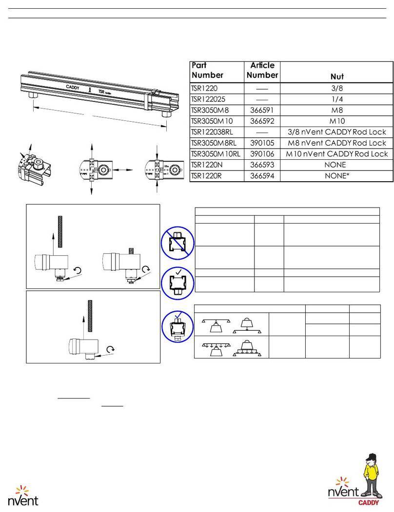
III. CADDY TELESCOPING STRUT REPLACEMENT, NO NUT
In addition to standard channels, the SLS3 Locking Device can also be used with the nVent CADDY
Telescoping Strut Replacement, No Nut (TSR1220N). The TSR1220N is similar to strut, because it mimics
the profile of standard strut. However, it is different because it can telescope to any distance between
approximately 12” [30 cm] and 20” [50 cm]. Each TSR1220N has two holes pre-cut into each end that
can accommodate the SLS3 locking device. Combining these 2 Products creates a telescoping trapeze
solution with the flexibility of the wire rope system. It is the ideal solution for light and medium duty
applications such as: conduit, small copper pipes, duct and cable tray.
When calculating static load of the TSR1220N and SLS3, use the load limits of the TSR1220N.
Visit nVent.com/CADDY for more information.
IV. CEILING FAN UNIT
The SLS can also be used to support ceiling fans or other HVAC units.

nVent.com/CADDY |11
4. Speed Link Certicates & Listings
Speed Link is listed with UL for Cable and
Conduit Supports and for Luminaires.
5. Additional Warnings and Safety Instructions
When using Speed Link, the following must be observed:
• Load ratings must be followed
• Load must be static and stable
• All the Speed Link components must be free of oil or any other sort of grease and lubricants
• All the Speed Link components must be free of any paint, varnish or any other coating
• Product should be installed in an indoor, non-corrosive environment

nVent.com/CADDY
WARNING: nVent products shall be installed and used only as indicated in nVent’s product instruction sheets and training materials. Instruction sheets are available at
nVent.com/CADDY and from your nVent customer service representative. Improper installation, misuse, misapplication or other failure to completely follow nVent’s
instructions and warnings may cause product malfunction, property damage, serious bodily injury and/or death, and void your warranty.
©2018 nVent. All nVent marks and logos are owned or licensed by nVent Services GmbH or its aliates. All other trademarks are the property of their respective owners.
nVent reserves the right to change specications without notice.
CADDY-TH-FM1350W-DFM475LT17WW-EN-1805
CADDY ERICO HOFFMAN RAYCHEM SCHROFF TRACER
Our powerful portfolio of brands:
This manual suits for next models
2
Table of contents
Other nvent Lock manuals