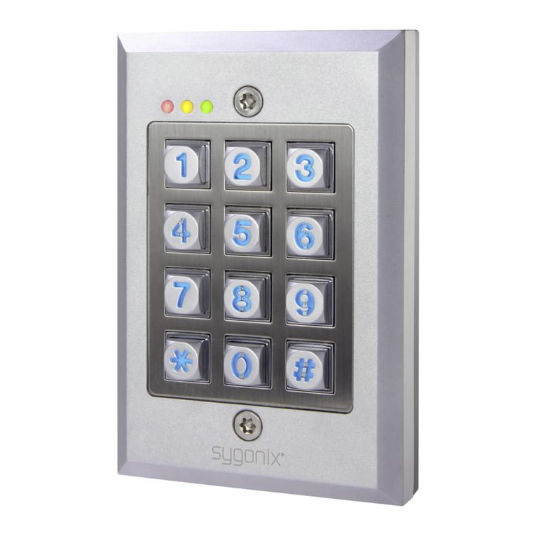
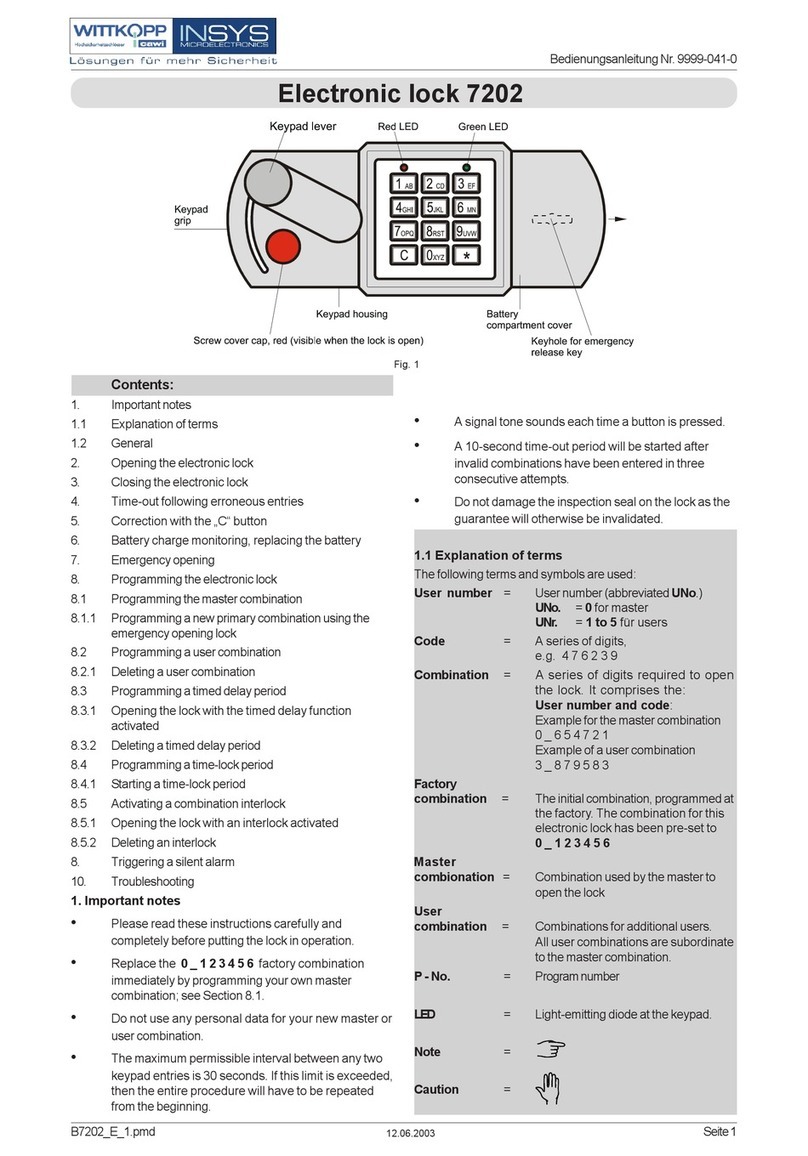
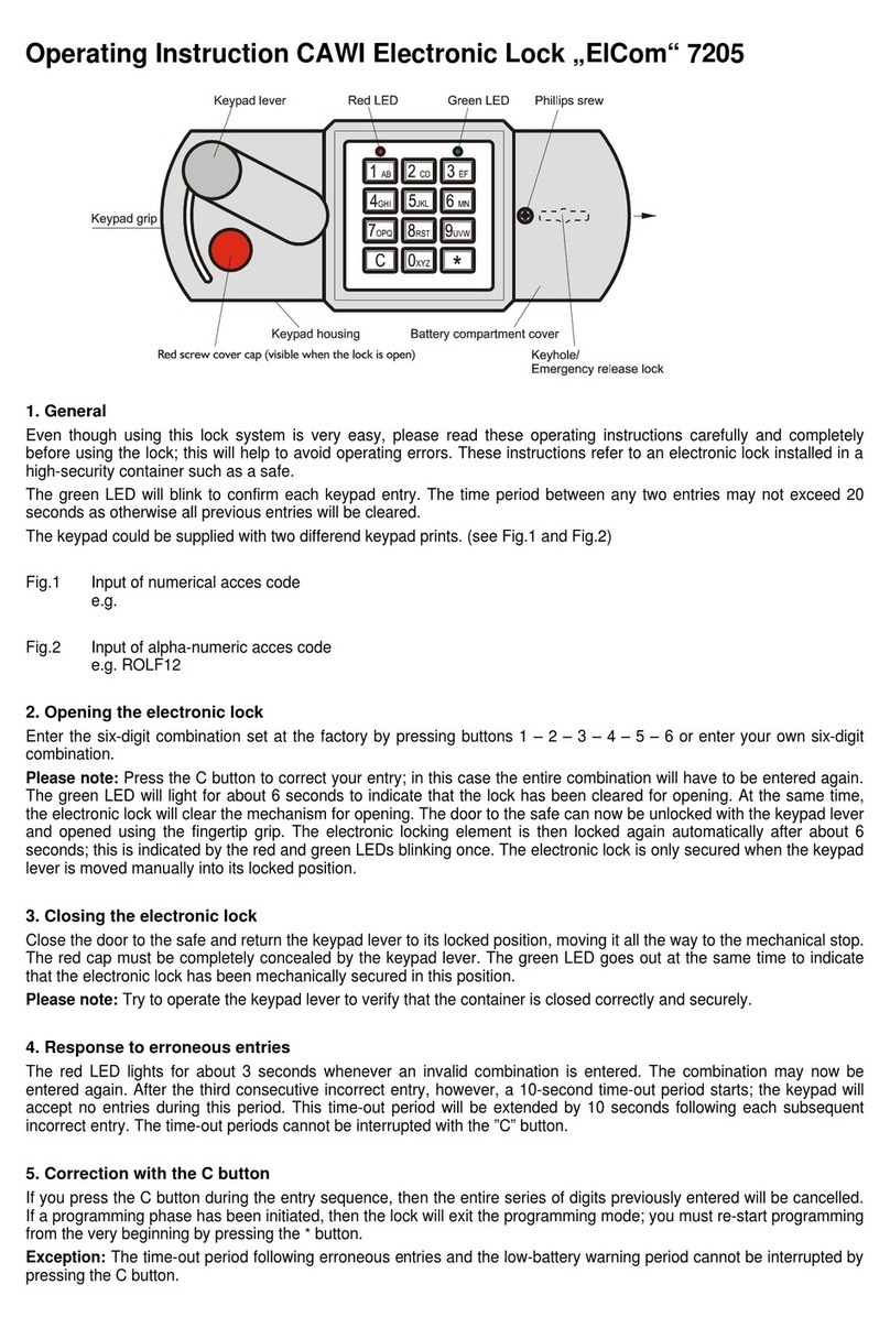
Sygonix 2250408 User manual

Operating Instructions
Waterproof code lock IP65
Item No. 2250408 Page 2 - 49
Notice d’emploi
Serrure à code étanche IP65
N° de commande 2250408 Page 50 - 102
Gebruiksaanwijzing
Waterdicht codeslot IP65
Bestelnr. 2250408 Pagina 103 - 154
Istruzioni
Blocco codice impermeabile IP65
N°.: 2250408 Pagina 155 - 205
Instrukcja użytkowania
Wodoodporny zamek szyfrowy IP65
Nr zamówienia: 2250408 Strona 206 - 259

Table of contents
Page
1. Introduction...........................................................................5
2. Explanation of symbols ........................................................6
3. Intended use.........................................................................6
4. Package contents.................................................................7
5. Features and functions.........................................................8
6. Precautions ..........................................................................9
a) General information.........................................................9
b) Connected devices........................................................10
c) Persons and product.....................................................11
d) (Rechargeable) batteries...............................................11
7. Controls..............................................................................12
8. Installation and connection.................................................13
a) Installation.....................................................................13
b) Door opener design.......................................................15
9. Connection .........................................................................16
a) Assignment of the connection contacts.........................16
b) Circuit diagram with connections ..................................18
2

10. Operation............................................................................20
a) Open and lock door.......................................................20
11. Operation............................................................................22
a) Inserting the batteries (keypad).....................................22
b) Low battery indicator.....................................................22
c) Replacing the batteries (keypad) ..................................22
d) Replacing the battery (opening button).........................23
e) Pairing the components ................................................24
12. Beeps and LED indicators..................................................26
13. Programming......................................................................27
a) Quick overview for programming ..................................27
b) Enable programming mode...........................................28
c) Conguringanewmastercode ....................................29
d) Programming regular users...........................................30
e) Programming 125 kHz EM cards for regular users.......31
f) Programming visitor PIN codes.....................................32
g) Changing user PIN codes.............................................34
h) Deleting user PIN codes ...............................................35
i) Setting the access mode...............................................36
j) Programming the relay behaviour.................................37
k) Conguringthebell.......................................................39
l) Reaction of the code lock to incorrect entries...............40
m) Tamper alarm ................................................................41
3
n) Conguringthebuzzer..................................................42
o) Programming the door open warning............................43
p) Programming the forced opening alarm........................44
q) Programming reset cards..............................................44
r) Restoring factory settings..............................................46
14. Care and cleaning ..............................................................46
15. Declaration of Conformity (DOC)........................................47
16. Disposal..............................................................................47
a) Product..........................................................................47
b) Batteries........................................................................48
17. Technical data ....................................................................48
4

1. Introduction
Dear customer,
Thank you for purchasing this product.
This product complies with statutory, national and European reg-
ulations.
To ensure that the product remains in this state and to guarantee
safe operation, always follow the instructions in this manual.
These operating instructions are part of this product.
They contain important information on setting up and
using the product. Do not give this product to a third
party without the operating instructions. Keep these op-
erating instructions in a safe place for future reference.
If there are any technical questions, please contact: www.conrad.
com/contact
5

2. Explanation of symbols
The symbol with the lightning in a triangle indicates that
there is a risk to your health, e.g. due to an electric
shock.
The symbol with an exclamation mark in a triangle is
used to highlight important information in these operat-
ing instructions. Always read this information carefully.
The arrow symbol indicates special information and tips
on how to use the product.
3. Intended use
This product is designed to secure doors against unauthorised
access(e.g. inan ofceorhome). Itconsists ofakeypad for
entering codes wirelessly, a relay and a wireless opening button
to open the door from the inside. The code lock can store up to
500 users (user IDs) with different codes (standard user codes)
as well as 100 temporary visitor codes. It also features a relay
output (1x switch contact, max. 12 V/DC, 2 A), which can be used
to control a door opener or other devices (e.g. an alarm system).
The opening button is powered by a CR2032 lithium battery. The
relay must be powered with a 12 V/DC power supply. The keypad
is powered by 3x AAA batteries.
6

The keypad can be installed and used outdoors. The other com-
ponents can only be used in enclosed areas. They are not suit-
able for outdoor use. Contact with moisture (e.g. in a bathroom)
must be avoided under all circumstances.
For safety and approval purposes, do not rebuild and/or modify
this product. Using the product for purposes other than those de-
scribed above may damage the product. In addition, improper use
cancausehazardssuchasashortcircuit,reorelectricshock.
Read the operating instructions carefully and store them in a safe
place. Only make this product available to third parties together
with its operating instructions.
All company and product names included herein are trademarks
of their respective owners. All rights reserved.
4. Package contents
• 1 x keypad
• 1 x relay
• 1 x opening button (with CR2032)
• 1 x reset card
• 2 x double-sided adhesive tape
• 1 x 1N4004diode
• 4 x mounting screws
• 4 x dowels
• 1 x screwdriver
7

• 1 x hex key
• User manual
1Up-to-date operating instructions
Download the latest operating instructions at
www.conrad.com/downloads or scan the QR
code shown. Follow the instructions on the
website.
5. Features and functions
• Code lock with wireless keypad (up to 30 m range)
• Up to 600 user codes or EM cards (500 normal users and 100
visitors)
• Keypad with IP65 protection rating (outdoor installation and
operation)
8

6. Precautions
Read the operating instructions and safety infor-
mation carefully. If you do not follow the safety
information and information on proper handling
in these operating instructions, we will assume
no liability for any resulting personal injury or
damage to property. Such cases will invalidate the
warranty/guarantee.
a) General information
• The device is not a toy. Keep it out of the reach of
children and pets.
• Do not leave packaging material lying around
carelessly. It may become a dangerous plaything
for children.
• Protect the product from extreme temperatures,
direct sunlight, strong jolts, high humidity, moisture,
ammablegases,vapoursandsolvents.
• Do not place the product under any mechanical
stress.
9

• If it is no longer possible to operate the product
safely, stop using it and prevent unauthorised use.
Safe operation can no longer be guaranteed if the
product:
- is visibly damaged,
- is no longer working properly,
- has been stored for extended periods in poor
ambient conditions or
- has been subjected to any serious transport-
related stress.
• Handle the product carefully. Jolts, impacts or a fall
even from a low height may damage the product.
• Consult a technician if you are not sure how to use
or connect the product, or if you have concerns
about safety.
• Maintenance, modications and repairs must be
carried out by a technician or a specialist repair
centre.
• If you have any questions which are not answered
in these operating instructions, contact our techni-
cal support service or other technical personnel.
b) Connected devices
• Always observe the safety information and oper-
ating instructions of any other devices which are
connected to the product.
10

c) Persons and product
• The relay switch contact has a maximum contact
rating of 12 V/DC, 2 A. It must never be used with
a higher voltage, other type of voltage (e.g. mains
voltage) or high currents. This may cause a fatal
electric shock!
• This moisture-sensitive components of the prod-
uct must only be installed and used in dry indoor
rooms.
• Do not use the product in environments where
there are high levels of dust, ammable gases,
vapoursorsolvents.Thismaycauseareorex-
plosion!
d) (Rechargeable) batteries
• Ensure that you insert the batteries in the correct
polarity.
• To prevent battery leakage, remove the batteries
when you do not plan to use the product for an ex-
tended period. Leaking or damaged batteries may
cause acid burns if they come into contact with your
skin. Always use suitable protective gloves when
handling damaged batteries.
• Batteries must be kept out of the reach of children.
Do not leave batteries lying around, as there is a
risk that children or pets may swallow them.
11

• All batteries must be replaced at the same time.
Mixing old and new batteries can cause the batter-
ies to leak and damage the product.
• Batteries must not be dismantled, short-circuited or
thrownintoopenames. Never rechargenon-re-
chargeable batteries. This may cause an explosion!
7. Controls
1
2
37
6
4
5
1 Symbol
2 Ring button
3 Keypad
4 Green LED
5 Red LED
6 Relay
7 Opening button
with EXIT
button and LED
indicator
12

8. Installation and connection
a) Installation
When installing the individual components, pay
attention to the range of the wireless signal. The
distance between the components must not exceed the
wireless range.
1Installation with double-sided adhesive tape
• The keypad and the wireless opening button can be attached
to smooth, clean surfaces with double-sided adhesive tape.
Removetheprotectivelmandsticktheadhesivetapetothe
backofthecomponents.Thecomponentscanthenbexedto
the mounting surface.
• All adhesive surfaces must be clean and free of grease to
ensure optimal adhesion of the adhesive tape.
2Installation with screws
• The keypad and the opening button can also be screwed to
suitable surfaces using the supplied screws and dowels.
• Remove the screw and back panel/base plate from the keypad.
• Use the wall base plate as a template. Place it on the mounting
surface and mark the mounting holes.
13

• Depending on the surface, use the dowels and the screws to
secure the base plate. On surfaces such as wood or plastic,
it is sufcient to use only the screws. Dowels are primarily
designed for mineral-based wall materials.
• Proceed as described above to screw the opening button in
place.
• The relay can only be secured with screws.
• Use the relay as a template and mark the necessary holes.
Proceed in the same way as described above to screw the
relay in place.
• Install the relay and the opening button on an internal wall.
Step 3 Step 2 Step 1
Wall
Use the xing screws, and if necessary, the dowels
provided to secure the housing to the wall. Ensure that
no cables or wires are damaged when drilling holes or
tightening screws.
14

b) Door opener design
The code lock can be used with fail-safe or fail-secure door open-
ers. The door opener must be connected differently depending on
its design. Make sure that the door opener is connected correctly.
Refer to section "b) Wiring diagram with connections" for more
information on connection options.
"Fail-secure" door openers: Fail-secure door openers release the
latch when the power supply delivers a voltage (standard door
opener type).
"Fail-safe" door openers: Fail-safe door openers release the latch
when the power supply stops delivering a voltage (non-standard
door opener type, used for emergency exit doors so that the door
opens in the event of a power cut).
Determine which type of door opener you are using
before connecting it. A fail-secure door opener requires
relatively high currents for a short time in order to open.
It is therefore not suitable for a prolonged load with a
highcurrentow.
15

9. Connection
Ensure that the connection cables are not kinked or
squashed. This can cause malfunctions, short circuits
and device defects. Only connect devices when the
product is disconnected from the power supply.
• Always place the cables bare/stripped into the screw
connectionsand tightenthemsufcientlywithascrewdriver.
Take care not to over-tighten them.
• Use the supplied screwdriver to connect the electrical
connections.
a) Assignment of the connection contacts
Contacts
on the
relay
Meaning
GND Negative pole ground connection (2x)
+12 V Positive pole 12 V/DC
ALARM Negative alarm contact
COM Connection for relay output
NO Connectionforrelay(fail-securecongu-
ration)
16

LOCK+ Positive connection for NO contact
NC Connectionforrelay(fail-safeconguration)
OPEN Connection for the opening button
D_IN Connection for detecting the opening/closing
status of the lock
BELL_A Connection for bell A
BELL_B Connection for bell B
• Connect the cables to the corresponding screw terminals.
Two circuit examples can be found in "b) Circuit diagram with
connections".
Never connect a mains voltage here! This may cause a
fatal electric shock!
Never connect a mains voltage here! This may cause a
fatal electric shock!
17

b) Circuit diagram with connections
1Relay power supply via NO contact
DC power supply
Fail-secure lock
Magnet or fail-
safe lock Bell
Door contact
Opening
button
2NO contact power supply via relay
Bell
Door contact
Opening
button
Fail-secure lock
Magnet or fail-
safe lock
DC power supply
18

b) Circuit diagram with connections
1Relay power supply via NO contact
DC power supply
Fail-secure lock
Magnet or fail-
safe lock Bell
Door contact
Opening
button
2NO contact power supply via relay
Bell
Door contact
Opening
button
Fail-secure lock
Magnet or fail-
safe lock
DC power supply
19

To avoid interference with the code lock functions due
to electrostatic discharge (ESD), always connect the
protective earth.
• Depending on the door closer to be connected, select the
correct connection option – fail-safe or fail-secure.
• The supplied diode should be connected as close as possible
to the N.O. contacts to prevent the code lock from being
damaged due to a current generated by an inductive coupling
in the N.O contact coil.
10. Operation
a) Open and lock door
1PIN access only
PIN access only is selected
Enter the user code (in the example, the
usercodeis"83221")andconrmyourentry
by pressing the # key.
The green LED (6) will turn on for 3 seconds
toconrm that thelock hasbeen opened.
The relay opens the connected switching
device, e.g. door opener. It automatically
closes again after the preset set time (de-
fault 5 seconds).
20
Table of contents
Languages:
Other Sygonix Lock manuals

Sygonix
Sygonix Touch S User manual

Sygonix
Sygonix 1559246 User manual

Sygonix
Sygonix 1717531 User manual

Sygonix
Sygonix 43172W User manual

Sygonix
Sygonix 2380478 User manual

Sygonix
Sygonix LKBK-2209 User manual

Sygonix
Sygonix UP IP66 User manual

Sygonix
Sygonix 2522226 User manual

Sygonix
Sygonix SY-4730012 User manual