NVT NV-216A-PV User manual

Wire Type
The PVD system operates well with Category Unshielded Twisted-Pair
(UTP) wire, 24-22 AWG (0,5-0,6mm). NVT signals may reside near
electromagnetic fields (in accordance with National Electrical Code, and
other local safety requirements).
ow voltage camera power, video and RS-422 or RS485 may be sent
within same wire bundle as datacom signals not telecom.
Do NOT use shielded twisted-pair wire unless it is Category rated. Multi-
pair wire with an overall shield (6 or more pairs) is OK.
Do NOT use un-twisted wire.
Wire in underground conduit or wet locations must be polyethylene-
jacketed, gel-filled.
Do not run 24/28 VAC within same wire bundle with telecom or other
datacom signals.
NVT recommends the use of factory-crimped RJ45 patch cables rather
than unreliable field-crimped RJ45s to connect between the NVT device
and an adjacent female RJ45 jack.
Measure Your Wire Distance
All NVT quoted distance specifications include any coax in the run. It is
recommended that the wire distance be measured to ensure that the
capability of the NVT product is correct.
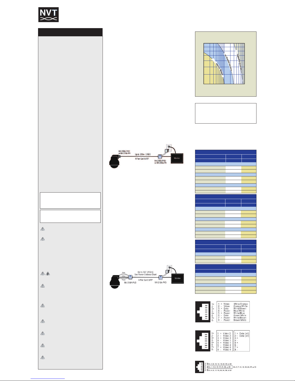
Vi eo Distance: Recommended wire distances for best resolution is
shown in Figure 1. Wire resistance may be measured with an ohm-meter
by shorting the two conductors together at the far end, and measuring the
loop-resistance out and back. See Figure 2.
Power-Vi eo Fixe camera
single channel application
Power and Video at the Camera End
1. Connect the baseband Video signal output from the camera to the
male BNC on the NV-216A-PV or NV-218A-PVD.
2. Connect the camera’s Power input to the 18AWG Power wires on the
NV-216A-PV or NV-218A-PVD. Verify wire distance, camera load and
wire resistance limit for the maximum distance that Power can travel
using Figure 3.
3. Connect the 4-pair Cat-5 using the NV-216A-PV’s or NV-218A-PVD’s
8-pin RJ45 connector on the UTP run to the Equipment Room as
shown in Figure 4.
Connecting the Power-Video at the Equipment Room End
1.Connect the baseband Video input twisted pair to the screwless
terminals adjacent to the RJ45 connector of the NV-218A-PVD, or
using the 8-pin RJ45 connector on the NV-216A-PV or NV-218A-PVD
as shown in Figure 4.
2.Connect the baseband Video signal output from the BNC pigtail on the
NV-218A-PVD or the BNC of the NV-216A-PV directly to the Video
monitor, multiplexer, or DVR.
3.Connect Power via a Class II (SE V) low-voltage Power supply. NVT
recommends the use of 18AWG solid wire. NVT also recommends
Power supplies with individually floating outputs.
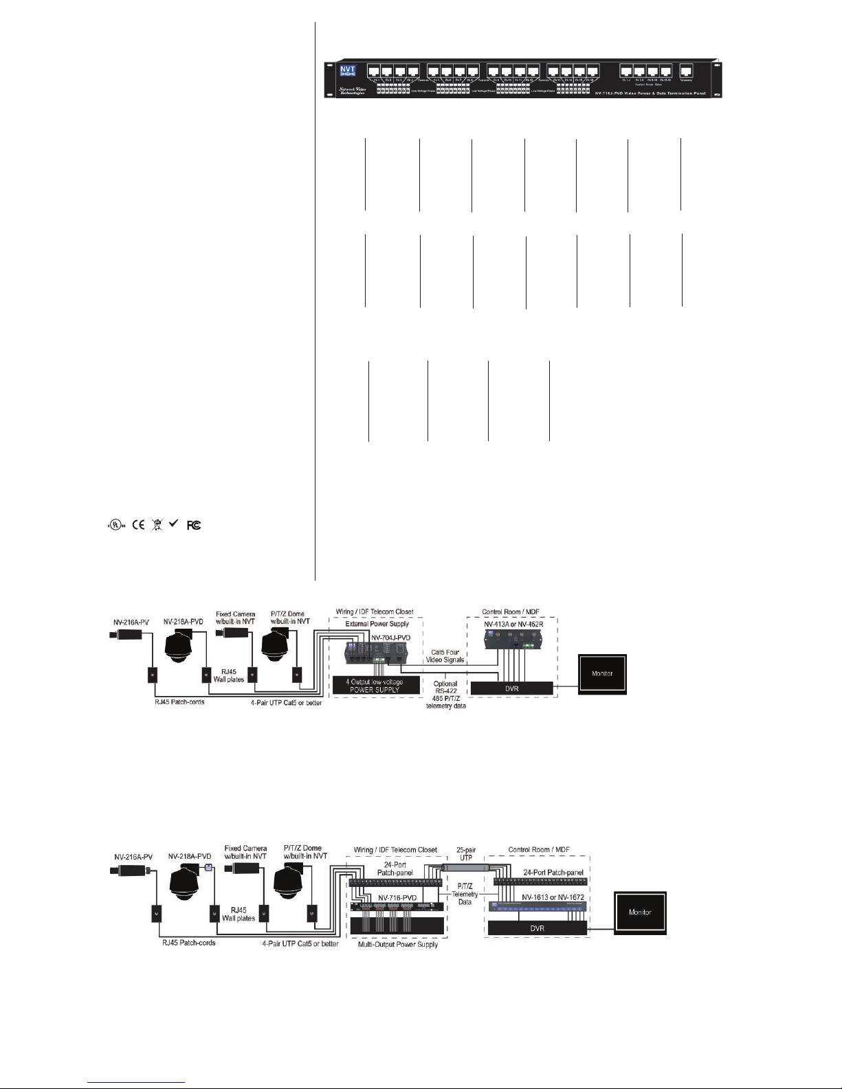
Power-Vi eo-Data P/T/Z camera
single channel application
Connecting Power-Video-Data at the Camera End
1. Connect the baseband Video signal output from the camera to the Male
BNC pigtail connector on the NV-218A-PVD.
2. Connect the camera’s Power input to the screwless terminals marked
Power on the NV-218A-PVD. Verify wire distance, camera load and wire
resistance limit for the maximum distance that Power can travel using
Figure 3.
3. If the camera supports P/T/Z telemetry over RS-422 or RS-485,
connect the camera’s Data terminals to the Data screwless terminals
on the NV-218A-PVD.
4. Connect the 4-pair Cat-5 using the 8-pin RJ45 connector on the UTP run
to the Control end as shown in Figure 4.
Connecting the Power-Video-Data at the Equipment Room
1. Connect the 4-pair Cat-5 from the camera end to the RJ45 connector
on the NV-218A-PVD.
2. Connect the baseband Video signal output from the BNC pigtail on the
NV-218A-PVD directly to the Video monitor, multiplexer or DVR.
3. Connect the control equipment data port to the screwless terminals
marked data on the NV-218A-PVD.
4. Connect the Power screwless terminals to a Class II (SE V) low-voltage
Power supply. NVT recommends the use of 18AWG solid wire. NVT also
recommends Power supplies with individually floating outputs.
1) Re d these instructions.
2) Keep these instructions.
3) Heed ll w rnings.
4) Follow ll instructions.
5) Do not use this pp r tus ne r w ter.
6) Cle n only with dry cloth.
7) Do not block ny ventil tion openings.
8) Inst ll in ccord nce with the m nuf cturer’s
instructions.
9) Do not inst ll ne r ny he t sources such s r di tors,
he t registers, stoves or other pp r tus (including
DVRs) th t produce he t.
10) Do not defe t the s fety purpose of the pol rized or
grounding-type plug. A pol rized plug h s two bl des with
one wider th n the other. A grounding type plug h s two
bl des nd third grounding prong. The wider bl de or
the third prong re provided for your s fety. If the provided
plug does not fit into your outlet, consult n electrici n for
repl cement of the obsolete outlet.
11)Protect the power cord from being w lked on or
pinched p rticul rly t plugs, convenience recept cles,
nd the point where they exit from the pp r tus.
12) Only use tt chments/ ccessories specified by the
m nuf cturer.
13) Use only with c rt, st nd, tripod, br cket, or t ble
specified by the m nuf cturer, or sold with the pp r tus.
When c rt is used, use c ution when moving the
c rt/ pp r tus combin tion to void injury from tipover.
14) Unplug this pp r tus during lightning storms or when
unused for long periods of time.
15) Refer ll servicing to qu lified service personnel.
Servicing is required when the pp r tus h s been
d m ged in ny w y, such s power supply cord or plug
is d m ged, liquid h s been spilled, or objects h ve f llen
into the pp r tus, the pp r tus h s been exposed to
r in or moisture, does not oper te norm lly, or h s been
dropped.
This installation should be made by a qualified service
person and should conform to all local codes.
WARNING - Do not install the unit in an
environment where the operating ambient
temperature exceeds 120° F (50° C). The ventilation
should not be impeded by covering the ventilation
openings with items, such as newspapers, table-
cloths, curtains, etc. No naked flame sources, such
as lighted candles should be placed on the
apparatus.
WARNING - Do not interconnect multiple
outputs.
WARNING - The apparatus shall not be exposed
to dripping or splashing and no objects filled with
liquids, such as vases, shall be placed on the
apparatus.
WARNING - Use only a Certified power cord and
plug (coupler / mains) assemblies for location
installed.
WARNING - Power cord is regarded as main
disconnect.
WARNING - The appliance coupler (power
cord/mains) shall remain readily operable.
WARNING - For safety, never put N T signals in
the same conduit as high-voltage wiring.
WARNING - Do not restrict airflow around any
active powered N T products.
TO REDUCE THE RISK OF ELECTRICAL SHOCK, DO
NOT REMO E CO ER OR BACK. NO USER
SER ICEABLE PARTS INSIDE. REFER SER ICING
TO QUALIFIED SER ICE PERSONNEL.
WARNING: TO REDUCE THE RISK OF ELECTRICAL
SHOCK, DO NOT EXPOSE THIS APPARATUS TO RAIN
OR MOISTURE.
IMPORTANT SAFETY INSTRUCTIONS
Power-Vi eo-Data CCTV Pro uct Installation Manual
Mo els NV-216A-PV, NV-218A-PVD, NV-704J-PVD an NV-716J-PVD
Figure 4 Transceiver Pinouts & UTP Wire Colors
Figure 5 Control End Pinouts (NV-704J-PVD)
Figure 3 Power Distance Charts
24AWG (0,5mm) = 52Ohms per300m
22AWG (0,6mm) = 32Ohms per 300m
20AWG (0,7mm) = 20Ohms per 300m
19AWG (0,8mm) = 16Ohms per 300m
18AWG (1,0mm) = 13Ohms per 300m
16AWG (1,3mm) = 8.2Ohms per 300m
Figure 2 Resistance per 1,000 ft (300 m) out and back
Camera Power Distance: Different cameras draw different
amounts of current. It is important to make sure that the
voltage-drop on the wire allows sufficient voltage for the
camera to operate properly. A camera voltage of 21VAC or
greater is usually acceptable. Figure 3 shows typical wire
distances for standard camera configurations.
Cat 5 Wire Distance
Cat 5 Wire Distance
235
315
400
475
550
630
700
780
3 MHz
4MHz
5MHz
6 MHz
9 MHz
8 MHz
7MHz
10 MHz
100ft
Camera Lines of Resolution
Frequency
300ft
1,000ft
1 mile
3,000ft
10,000ft
30m
100m
300m
1,6km
1km
3km
M
a
x
P
a
s
s
i
v
e
D
i
s
t
a
n
c
e
M
a
x
S
t
u
b
E
Q
D
i
s
t
a
n
c
e
M
a
x
D
i
g
i
t
a
l
E
Q
D
i
s
t
a
n
c
e
Figure 6 Control End Pinouts
Figure 1 Video Distance Recommendations
Fixed Camera 24VAC only, used with NV-216A-PV
Power Supply Voltage
Minimum Voltage at Camera
789ft (240m)
994ft (303m)
393ft (120m)
495ft (151m)
262ft (80m)
331ft (101m)
1,840ft (561m)
2,320ft (707m)
916ft (279m)
1,155ft (352m)
612ft (186m)
771ft (235m)
B&W Camera, 2.4 W
2-pair 24 AWG
2-pair 23 AWG
Color Camera, 4.8 W
2-pair 24 AWG
2-pair 23 AWG
Color Camera, 7.2 W
2-pair 24 AWG
2-pair 23 AWG
24 VAC
21 VAC
28 VAC
21 VAC
Fixed 12VDC Camera used with NV-226J-PV
Power Supply Voltage
1,586ft (748m)
1,999ft (609m)
795ft (242m)
1,002ft (306m)
2,220ft (677m)
2,799ft (853m)
1,113ft (339m)
1,403ft (428m)
B&W Camera, 2.4 W
2-pair 24 AWG
2-pair 23 AWG
Color Camera 4.8 W
2-pair 24 AWG
2-pair 23 AWG
24 VAC 28 VAC
P/T/Z 24VAC Camera used with NV-218A-PVD
Power Supply Voltage
Minimum Voltage at Camera
90ft (27m)
113ft (35m)
210ft (64m)
265ft (81m)
P/T/Z Camera, 21 W
2-pair 24 AWG
2-pair 23 AWG
24 VAC
21 VAC
28 VAC
21 VAC
Fixed Dual Voltage 24VAC/12VDC Camera with NV-216A-PV
Power Supply Voltage
Minimum Voltage at Camera
1,753ft (534m)
2,210ft (674m)
874ft (266m)
1,102ft (336m)
583ft (178m)
735ft (224m)
2,454ft (748m)
3,094ft (943m)
1,223ft (373m)
1,542ft (470m)
816ft (249m)
1,029ft (314m)
B&W Camera, 2.4 W
2-pair 24 AWG
2-pair 23 AWG
Color Camera, 4.8 W
2-pair 24 AWG
2-pair 23 AWG
Color Camera, 7.2 W
2-pair 24 AWG
2-pair 23 AWG
24 VAC
14 VAC
28 VAC
14 VAC

Power-Vi eo-Data at the Camera En
1.Connect the NV-216A-PV or the NV-218A-PVD as shown in the examples on the other side.
2.Connect the 4-pair Cat5 UTP cables coming from the cameras into the appropriate camera port on the NV-704J-PVD using the RJ45 connector as shown in Figure 4 (previous page).
3.Connect the outputs of your independent power supply into the appropriate Camera Power terminals on the NV-704J-PVD. Torque to 2 in-lbs (0.22 Nm). NVT recommends the use of 18AWG (1,0 mm)
solid conductor wire. NVT also recommends that the external power supply have individually floating outputs.
Power-Vi eo-Data at the Equipment Room En
4.Connect the NV-704J-PVD’s Control Room outputs to the NV-413A or NV-452R via UTP using RJ45 connectors and Cat5 cable. The control end pinouts are listed in Figure 5 (previous page). If P/T/Z
telemetry is required, connect a second RJ45 Cat5 cable from the data port to the DVR’s RS-422 or RS-485, control output.
Power-Vi eo-Data at the Camera En
1. Connect the NV-216A-PV or the NV-218A-PVD as shown in the examples on the other side.
2. Connect the 4-pair Cat5 UTP cables coming from the cameras into the appropriate camera port on the NV-716J-PVD using the RJ45 connector as shown in Figure 4 (previous page).
3. Connect the outputs of your independent power supply into the appropriate Camera Power terminals on the NV-716J-PVD. Torque to 2 in-lbs (0.22 Nm) Figure 5 (previous page). NVT
recommends the use of 18AWG (1,0 mm) solid conductor wire. NVT also recommends that the external power supply have individually floating outputs.
Power-Vi eo-Data at the Equipment Room En
4. Connect the NV-716J-PVD’s Control Room outputs to the NV-1613, NV-1613S, NV-1662 or NV-1672 via UTP using RJ45 connectors and Cat5 cable. See the NV-716J-PVD wiring
diagram above. If P/T/Z telemetry is required, connect additional RJ45 Cat5 cable(s) from the data port(s) to the DVR’s RS-422 or RS-485 Code Converter (alternately known as a
data distribution unit or fan-out unit.) Additional details can be found at www.nvt.com.
NV-716J-PVD Wiring Diagram
Channel 1 Channel 2 Channel 3 Channel 4 Channel 5 Channel 6 Channel 7 Channel 8
1Video 1+ 1Video 2+ 1Video 3+ 1 Video 4+ 1 Video 5+ 1Video 6+ 1Video 7+ 1Video 8+
2Video 1- 2Video2- 2Video 3- 2 Video 4- 2 Video 5- 2Video 6- 2Video 7- 2 Video 8-
3Data A + 3 Data A + 3 Data A + 3 Data A + 3 Data B + 3Data B + 3 Data B + 3 Data B +
4Power 1- 4 Power 2- 4 Power 3- 4Power 4- 4Power 5- 4Power 6- 4Power 7- 4Power 8-
5Power 1+ 5Power 2+ 5Power 3+ 5Power 4+ 5Power 5+ 5Power 6+ 5Power 7+ 5Power 8+
6Data A - 6 Data A - 6 Data A - 6Data A - 6 Data B - 6 Data B - 6 Data B - 6Data B -
7Power 1+ 7Power 2+ 7Power 3+ 7Power 4+ 7Power 5+ 7Power 6+ 7Power 7+ 7Power 8+
8Power 1- 8 Power 2- 8 Power 3- 8Power 4- 8Power 5- 8Power 6- 8Power 7- 8Power 8-
Channel 9 Channel 10 Channel 11 Channel 12 Channel 13 Channel 14 Channel 15 Channel 16
1Video 9+ 1Video 10+ 1 Video 11+ 1Video 12+ 1Video 13+ 1 Video 14+ 1 Video 15+ 1 Video 16+
2Video 9- 2Video10- 2Video11- 2Video12- 2Video 13- 2 Video 14- 2Video 15- 2 Video 16-
3Data C + 3Data C+ 3Data C+ 3Data C+ 3Data D + 3 Data D+ 3Data D+ 3Data D+
4Power 9- 4 Power 10- 4 Power 11- 4 Power 12- 4 Power 13- 4Power 14- 4Power 15- 4Power 16-
5 Power 9+ 5Power 10+ 5 Power 11+ 5 Power 12+ 5 Power 13+ 5 Power 14+ 5Power 15+ 5Power 16+
6 Data C - 6 Data C - 6Data C - 6 Data C - 6Data D- 6Data D- 6Data D- 6Data D-
7 Power 9+ 7Power 10+ 7 Power 11+ 7 Power 12+ 7 Power 13+ 7 Power 14+ 7Power 15+ 7Power 16+
8 Power 9- 8 Power 10- 8 Power 11- 8 Power 12- 8 Power 13- 8Power 14- 8Power 15- 8Power 16-
Camera Connections
Limite Lifetime Warranty
NVT warrants that the product conforms to NVT’s applicable published
specifications and is free of defects and workmanship, for the life of
the product.
There shall be no other warranties, express, statutory or otherwise,
including any implied warranty of merchantability of fitness or any
other obligation on the part of NVT with respect to any of the products.
In the event that any product is damaged or altered or modified
without the express written consent of NVT, any warranty for those
products will cease and NVT will have no further liability as it pertains
to those products. NVT assumes no responsibility for damages or
penalties incurred resulting from the use of this product in a manner
or location other than for which it is intended.
NVT’s liability under any warranties shall be discharged by replacing
or repairing any part or parts which do not conform to the applicable
warranty under normal and proper use. NVT’s liability with respect to
any product shall not exceed a refund of the price received by NVT for
that product, and in no event shall NVT have any liability for any
incidental, consequential, special, or indirect damages.
Some states do not allow the exclusion or limitation of special, incidental
or consequential damages, so the above limitation or exclusion may not
apply to you. This warranty gives you specific legal rights, and you may
also have other rights which vary from state to state.
Customer Support
If you are experiencing problems, attempt to simplify your setup. Test
each cable segment separately. For example, test the camera and
monitor together without the other equipment. Then add in the NVT
transceivers, back-to-back. Test each segment of a long cable-run
independently. Attempt to isolate the problem.
NVT customer support is available for consultation from 8:00 AM to
5:30 PM PST Monday through Friday. In addition, emergency after-
hours callback support is available.
US Office: (+1) (650) 462-8100
US Fax: (+1) (650) 326-1940
UK Office: (+44) (0)20 8977 6614
UK Fax: (+44) (0)20 8973 1855
Email USA: www.nvt.com/email
Email UK: www.nvt.com/email
Web home page: www.nvt.com
Returns
Please call before returning units to NVT. Returned materials must
have a “Returned Materials Authorization” (RMA) number from NVT
marked on the outside of the shipping carton.
Agency
These NVT products are listed and/or conform to the following
certifications and directives:
U isted to U 2044 or U /IEC 60065.
cU isted to CAN/CSA22.2 No. 1 for Canada.
CE Mark under EMC and low voltage
Complies with FCC part 15B limits
Directives for the European Union.
Channel 1-4 Channel 5-8 Channel 9-12 Channel 13-16 Data/Telemetry
1 Video 2+ 1Video 6+ 1Video 10+ 1Video 14+ 1 Data B+
2 Video 2- 2Video6- 2Video10- 2Video 14- 2 Data B-
3 Video 3+ 3Video 7+ 3Video 11+ 3Video 15+ 3 Data C+
4 Video 1- 4Video5- 4Video9- 4Video 13- 4 Data A-
5 Video 1+ 5Video 5+ 5Video 9+ 5 Video 13+ 5 Data A+
6 Video 3 - 6 Video 7 - 6 Video 11 - 6 Video 15- 6 Data C-
7 Video 4+ 7Video 8+ 7Video 12+ 7Video 16+ 7 Data D+
8 Video 4- 8Video8- 8Video12- 8Video 16- 8 Data D-
Control Room Connections
Power-Vi eo-Data 4-Channel Application using the NV-704J-PVD at the Telecommunications Closet or IDF
Power-Vi eo-Data 16-Channel Application using the NV-716J-PVD at the Telecommunications Closet of IDF
Copyright (c) 2011 NVT, Inc. 451-218-1-H
08/11
RoHS
Figure 7 Control End Pinouts (NV-716J-PVD)
This manual suits for next models
3
Table of contents
Popular Security System manuals by other brands

Scorpio
Scorpio SR-i800 Installation manual and user's guide

Metra Electronics
Metra Electronics TE-DVR-MM user manual

Easywave
Easywave RTRP02 series Operating instruction

Allen-Bradley
Allen-Bradley Ferrogard Series installation instructions

ecoey
ecoey FJ128 user manual

Federal Signal Corporation
Federal Signal Corporation SST-MV Installation and maintenance manual