Telemic HouseControl E+ User manual

+
INSTALLATION MANUAL
1.0
HOME ENERGY SAVINGS
REMOTE CAMERA
INTERNET USER INTERFACE
TEMPERATURE ALARMS
BURGLARY PROTECTION
DOOR SECURITY
FIRE SAFETY
SECURITY KEYPAD WITH PROXIMITY TAGS
PREVENTION OF WATER DAMAGES
WIRELESS EXTENSIONS


Inst ll tion Certific te
This certific te st tes th t Telemic Oy’s HouseControl remote control nd l rm system h s been
inst lled in the re l est te mentioned below.
Property holder / holder of real estate
Location of the real estate
Real estate
Alarm system type
Central unit’s serial number
SIM card phone number
Smoke detector model
Motion sensor model
Magnetic door s itches
Remote camera
Security keypad
Siren
Installed by
We ssure
- that the alarm system as installed in accordance ith the manufacturer’s instructions.
- that the alarm system has been tested and it orks as documented.
- that the end user has received guidance as to ho to use the alarm system.
Loc tion nd d te
Inst lled by / Sign ture
This form needs to be filled and signed in order to apply for possible refund from your insurance company and
before contacting product support.


1
1.
INTRODUCTION....................................................................................................................... 2
2.
PREPARATION........................................................................................................................ 2
2.1
R
EQUIRED
T
OOLS
............................................................................................................... 2
2.2
P
ACKAGE
C
ONTENTS
.......................................................................................................... 3
2.3
A
CCESSORIES
.................................................................................................................... 3
3.
INSTALLATION........................................................................................................................ 4
3.1
O
PENING
U
NIT
’
S
C
OVER
..................................................................................................... 4
3.2
HCE+
FROM
I
NSIDE
............................................................................................................ 4
3.3
C
ONNECTORS
.................................................................................................................... 4
3.4
C
ENTRAL
U
NIT
................................................................................................................... 5
3.5
R
EMOTE
C
AMERA
............................................................................................................... 6
3.6
I
NDOOR
T
EMPERATURE
S
ENSOR
.......................................................................................... 6
3.7
O
UTDOOR
T
EMPERATURE
S
ENSOR
...................................................................................... 6
3.8
W
ATER
T
EMPERATURE
S
ENSOR
.......................................................................................... 7
3.9
S
IREN
............................................................................................................................... 7
3.10
M
AGNETIC
D
OOR
S
WITCHES
................................................................................................ 7
3.11
M
OISTURE
S
ENSOR
............................................................................................................ 8
3.12
M
OTION
S
ENSOR
................................................................................................................ 8
3.13
S
MOKE
D
ETECTOR
............................................................................................................. 9
3.14
S
ECURITY
K
EYPAD
........................................................................................................... 10
3.15
H
EATER
R
ELAY
................................................................................................................ 11
3.16
EXT
R
ELAY
..................................................................................................................... 11
3.17
P
OWER
S
UPPLY AND
B
ATTERY
B
ACKUP
U
NIT
...................................................................... 12
3.18
SIM
C
ARD
....................................................................................................................... 12
3.19
W
IRELESS EXTENSION
...................................................................................................... 13
4.
SETUP AND TESTING ........................................................................................................... 13
4.1
T
ESTING
.......................................................................................................................... 13

2 HouseControl E+ Installation Manual
1. INTRODUCTION
This manual describes the installation of HouseControl remote control and alarm system. The
instructions in this manual can be applied to many kinds of houses.
It is important that you plan carefully ho you are going to install HouseControl. For example, to achieve
finished look make sure the cables run inside the alls and other structures. This requires that you have
a plan for here you are going to install smoke detectors, motion sensors, and other accessories as you
are building your house.
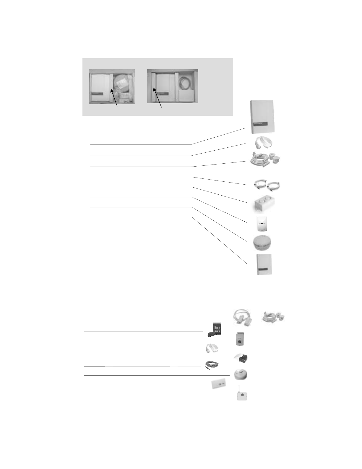
You can connect up to three temperature sensors, a siren, a magnetic door s itch, a moisture sensor, a
smoke detector, a motion sensor, a security keypad, a remote camera and a control panel to the central
unit. You can connect several motion sensors, magnetic door s itches, smoke detectors and moisture
sensors to one input. Al ays connect the sensors according to the separate iring diagram.
The central unit contains t o relay outputs 230VAC/AC (6A and 10A). The 10A relay can be controlled
thermostatically.
2. PREPARATION
You need a GSM subscription and a SIM card from a telecommunications operator for testing and using
HouseControl. You must disable the PIN code request from the SIM card before inserting the card in the
central unit. It is recommended that testing is conducted ith the same SIM card that ill remain in the
central unit after the installation is complete.
If a camera is installed, you should make sure that MMS messages (messages that contain pictures)
can be sent from the subscription. Some operators require that the service is activated before it can be
used. You can activate MMS by inserting the SIM card in an MMS compatible phone and sending an
activation message to your operator. Please consult your telecommunications operator for more
information. Before inserting the SIM card in HouseControl make sure that you indeed can send MMS
messages ith that SIM card by testing it ith your mobile phone.
Use n unlisted phone number in your HouseControl so th t it is not publicly v il ble. However,
m ke sure th t the HouseControl’s phone number is displ yed on the screen of your mobile
phone when it c lls you (i.e. HouseControl’s phone number is sent with the c ll nd is not
hidden).
2.1 Required Tools
You ill need the follo ing tools:
• Side cutters for cables
• Pointed pliers to help you connect ires to connectors
• Electrical drill and drill bits of various sizes
• Scre driver

PREPARATION 3
2.2 P ck ge Contents
2.3 Accessories
The follo ing accessories are available to HouseControl:
Security keypad ith proximity tags
Remote camera
Moisture sensor
Siren ith light
Temperature sensor
Heat detector
Carbon monoxide detector
HCE Wireless extension: detectors and remote controls
Magnetic door s itch (flush and surface mounting)
Temperature sensors
Battery
Moisture sensor
Battery backup unit package
Central unit package
Check the package contents:
Central unit
Magnetic door s itch (flush mounting)
2 temperature sensors
Siren
Motion sensor
Smoke detector
Battery backup unit
And:
- Materials needed in installation
- Installation cable
- User’s Manual and Installation Manual

4 HouseControl E+ Installation Manual
3. INSTALLATION
3.1 Opening Unit’s Cover
There is a small curved indentation on the top of the central unit.
Place your hand into the indentation and carefully detach the
cover.
The cover must be fastened ith scre s after installation is
complete. The scre s are included in the package.
3.2 HCE+ from Inside
1. Heater/Aircon relay (see 3.3)
2. Ext relay (see 3.3)
3. Camera and data connector
4. Inputs for temperature sensors, siren, magnetic door
s itches, moisture sensor, motion sensor, smoke detector,
security keypad and 12V po er supply (see 3.3)
5. Cable holder
6. SIM card slot
7. Po er s itch
8. Tamper s itch
9. Manual heating s itch (red light is on hen manual control
is used)
10. Door security on/off s itch
3.3 Connectors
Do not use your fingers hen inserting ires into the spring clips
– Relays may be damaged if you push your fingers against them.
1
2
3
4
5
6
7
8
9
10

INSTALLATION 5
Al ays use a scre driver and pointed pliers hen inserting ires
into the connectors. Push spring clips almost directly from the top
ith a scre driver.
Before connecting individual ires to the connectors, peel off
about 10 cm of the insulation from the cable. Join the uninsulated
conductor to earth by using a connector strip (see separate iring
diagram).
The DOOR, IR (motion sensor) and FIRE (smoke detector) inputs
have been short circuited ith yello ires.
This prevents alarms from the inputs that do not have sensors
connected to them. When connecting a sensor to an input,
remove the corresponding yello ire.
NOTE. Moisture sensor and security keypad are normally open.
Do not short circuit them.
3.4 Centr l Unit
The central unit should be installed in a protected area. No intruder should get to the central unit past the
magnetic door s itch or ithout the motion sensor being able to detect the trespasser. You must have
an access to the central unit if you intend to use door security at night.
The signal light on the security keypad tells the current operating mode (is monitoring on or off).
Drill holes for the cables on the all. Leave at least 30
cm of surplus length to the cables to make installation
easier. Push surplus cable back inside the all after
you have connected the ires.
Fasten the central unit on the all ith three scre s
included in the package.
Alternatively, you can run the cables on the all surface if you ish to avoid drilling holes. If this is the
case, open the indentations on the side of the unit for the cables.
Note: Met l c sing (so c lled F r d y c ge) we kens the GSM sign l. If the device is inst lled in
met l c se, for ex mple n electric l c binet, you need to pl ce ntenn outside the c binet
(extern l ntenn is v il ble s n ccessory).
Note: Some other m teri ls lso we ken the GSM sign l, especi lly w lls th t cont in met l
fr ming.
Door
IR
Fire

6 HouseControl E+ Installation Manual
3.5 Remote C mer
You can connect Telemic Oy’s remote camera to your HCE+.
When choosing a location for the remote camera it is important to respect privacy and kno the la in
your country. HouseControl can take a picture automatically hen motion sensor detects movement.
Mount the camera. Remove the
lens cover.
Coil the surplus length of the
cable and hide it.
Connect the remote camera to the
central unit as depicted in the separate
iring diagram (lo er miniDin
connector).
You can adjust the direction of the camera by loosening the scre at the bottom.
3.6 Indoor Temper ture Sensor
Place the indoor temperature sensor in the living area in an unnoticeable place. Run the cable behind a
baseboard to the HCE+.
Note: Do not le ve sensors uninst lled. Shorten c bles s needed nd inst ll temp1 nd temp2
sensors inside HCE+ so th t there will be no unnecess ry temper ture l rms.
Place the temperature sensor in the
area here you ant to measure
temperature.
Hide the surplus of the cable.
Connect the temperature sensor
to the Temp1 connector as
depicted in the separate iring
diagram.
3.7 Outdoor Temper ture Sensor
Remember not to place the temperature sensor in direct sunlight.
Put the temperature sensor outside. Hide the surplus of the cable.
Connect the temperature sensor
to the Temp2 connector as
depicted in the separate iring
diagram.

INSTALLATION 7
3.8 W ter Temper ture Sensor
Slide the temperature sensor in the
casing pipe.
Hide the surplus of the cable. Connect the temperature sensor to
the Temp3 connector as depicted in
the separate iring diagram.
This sensor can be used for measuring other temperatures besides ater, and it can be named to describe its
usage better (see User’s Manual).
3.9 Siren
Install the siren in a such a place here it can be heard.
Note: If different siren (for ex mple n outdoor siren with bigger current consumption) is
connected to HCE+, you must use 12V output rel y in between. The current consumption of
the coil of the rel y must not exceed 300mA (12VDC).
Fasten the siren ith the
scre s included in the
package.
Connect the siren to the “Siren”
connector as depicted in the separate
iring diagram. Notice polarity (black
and red ires).
3.10 M gnetic Door Switches
Connect magnetic door s itches in series as sho n in the separate iring diagram. Install them in doors
and indo s that are most usually left open by accident. This prevents burglars from getting in, but also
prevents the house from cooling do n in the inter because of an open back door.
Connect the installation cable to the s itch as
depicted in the iring diagram. Use cover (D)
to protect the scre connectors.
Install the parts C and B so that they are no
more than 5mm apart from each other. Attach
part C to a all/door frame and part B to the
door by using scre s and t o-sided tape.
Bl ck -
Red +

8 HouseControl E+ Installation Manual
Hide the excess of the cable. Connect the installation cable to the Door
connector as depicted in the separate iring
diagram.
Drill a hole in the door frame for flush mounting. Push the s itch in the hole
ith your hands. Note! Do not use h mmer.
Alarm is not activated immediately hen the door is opened. The user must have some time to cancel
the alarm from the security keypad hen coming in (see User’s Manual).
Note: Inst ll the switch on the opposite side of the hinges.
3.11 Moisture Sensor
Moisture sensors are available as accessories. Install the sensor under a bypass manifold or a
dish asher. If there is a leakage in the ater pipe, ater ill flo in the casing pipe and come out near
the bypass manifold and eventually end up in the floor drain. By placing the moisture sensor under the
bypass manifold you can detect leakages easily.
Tape the sensor to the floor. Hide the excess of the cable. Connect the moisture sensor to the
Water connector as depicted in the
separate iring diagram.
3.12 Motion Sensor
Motion sensor should be installed in the living area here it has the best coverage for sensing
movement.
Do not install motion sensor in entrance hall if security keypad is in the same space. The user must be
able to come in and s itch monitoring off from the security keypad ithout activating the motion sensor.

INSTALLATION 9
Detach the cover of the motion sensor by opening the scre at the bottom.
Connect the motion sensor to the central unit as depicted in the separate
iring diagram. It is recommended that you make the follo ing adjustments
to the motion sensor:
- Turn the red scre counter clock ise to 11 o’clock.
- Change the Pet jumper to 25kg.
- Change the Pulse jumper to place 2.
The motion sensor orks best ith these settings in domestic environment.
By turning the red scre clock ise you can increase sensitivity.
Attach the motion
sensor to a all near
ceiling.
Hide the surplus of the cable. Connect the motion sensor to the IR
connector as depicted in the separate
iring diagram.
3.13 Smoke Detector
The smoke detector should be attached to the ceiling. Do not place the detector in a corner or cranny
because then it ill not detect smoke so easily.
Note: You c n connect up to 8 smoke detectors in the fire connector in HCE+.
Open the cover cerefully by using a
scre driver.
Connect the installation cable to
the smoke detector as depicted
in the separate iring diagram.
Place a battery in the detector. The
battery is used only hen po er
supply from HCE+ is cut off for some
reason.
Hide the surplus of the cable. Connect the smoke detector to the Fire connector as depicted in the
separate iring diagram.

10 HouseControl E+ Installation Manual
3.14 Security Keyp d
A security keypad is available as an accessory. Install the security keypad in the entrance hall in a place
here it can be used easily. The operating mode (is monitoring on or off?) is displayed by the signal light
on the security keypad. Make sure the signal light is not visible from outside.
Connect the RJ connector to the
security keypad.
Attach the security keypad to a all
in entrance hall.
Hide the excess of the cable. Connect the security keypad to the
GA and Ind1 connectors as depicted
in the separate iring diagram.
Note! Because the key reader on the security keypad uses radio frequencies, you should avoid placing it
near cables or devices that cause electromagnetic fields (contactors).
Security keypad is preprogrammed in such ay that nine keys can be used for changing the operating
mode (alarm on/off). Installer’s key cannot be used for this purpose. Operating mode can also be
changed by using a secret code. The codes are attached to the installer’s key.
To program security keypad (for example, if you ant to change individual codes), you need installer’s
key and installer’s code 1234. Do not ch nge the inst ller code bec use if inst ller’s proximity key
is lost, you c nnot progr m the security keyp d nymore. Keep the installer’s key in a safe place
a ay from the sun light.
To change monitoring on, bring one of the proximity keys in front of the keypad momentarily, OK light ill
flash. The round LED light starts blinking and hen exit delay is over it stops blinking and stays lighted
(monitoring is on). If you ant to cancel operating mode change during the exit delay, you can use your
key as described. The OK light flashes and the round LED light goes off. Tip! You can silence the siren
by using a proximity key ithout changing the operating mode.
To ch nge oper ting mode with code:
1. Press
2. Key in the four digit user code
3. Press
EN
CLR

INSTALLATION 11
To ch nge user code:
Switch to programming mode in security keyboard:
1. Press , and . and start blinking.
2. Bring installer’s key near the keypad. You ill hear a short signal tone and only blinks.
3. Key in installer code 1234 and press . You ill hear a long signal tone and starts
blinking.
To program a new user code:
4. Press , , , and . starts blinking.
5. Press , and . continues blinking.
6. Key in a ne 4 digit code. Press . continues blinking.
7. Repeat the ne 4 digit code you just entered. Press . is on for one second after hich
you ill hear a long signal tone. Note! Setting the user code to 0000 removes the user code
altogether.
Exit programming mode:
8. Press , and . The security keypad returns to normal user mode.
Note: Go through the aforementioned steps in one succession ithout interruption – other ise the
security keypad ill return to user mode automatically after a hile and the user code is not changed.
3.15 He ter Rel y
You can use HCE+ for controlling heating in your house. You can control an individual heater or an
entire heating system ith HCE+.
Connect the heater to the central unit (HEATER
relay).
Note: You cannot control heating from your
mobile phone if manual control is turned on.
Import nt: M ke sure th t m x lo d 230VAC/10A is not exceeded under ny circumst nces.
Import nt: When rel y is used to steer inductive lo d (for ex mple, nother cont ctor), connect
RC filter or EMC suppression component in p r llel to lo d to stop volt ge spikes when
cont ctor rele ses. Volt ge spike m y bre k the rel y.
3.16 EXT Rel y
There is a second relay in HCE+ (EXT) and its use can be selected freely. You can also set this relay to
auto mode hen it follo s device’s operating mode. If monitoring is on (ALARM ON), the relay pulls and
hen monitoring is off (ALARM OFF), the relay releases. This allo s you to easily s itch off electricity
and close ater pipe hen leaving home.
EXT relay can also be used as a LEAKGUARD. When moisture sensor detects moisture, the EXT relay
pulls. The relay releases hen leakguard is disabled or reset. When leakguard is in use, you cannot set
the relay on or off ith EXT command.
EN
2
FUN
EN
EN
EN
1
0
EN
6
4
FUN
EN
EN
2
FUN

12 HouseControl E+ Installation Manual
Connect the device to the EXT relay. You can
use the relay, for example, for controlling
magnetic valve in ater pipe and prevent ater
damages.
Import nt: M ke sure th t m x lo d 230VAC/6A is not exceeded under ny circumst nces.
Import nt: When rel y is used to steer inductive lo d (for ex mple, nother cont ctor), connect
RC filter or EMC suppression component in p r llel to lo d to stop volt ge spikes when
cont ctor rele ses. Volt ge spike m y bre k the rel y.
3.17 Power Supply nd B ttery B ckup Unit
1. Connect the cable from the battery
backup unit to the +12V and GND
connectors as depicted in the separate
iring diagram.
2. Connect the battery.
3. Attach the battery to the casing ith t o-
sided tape.
4. Connect the mains cable.
Make sure the HCE+ orks even if you detach the mains cable from the all outlet. This proves that the
battery has been connected properly and the 4A fuse is ok.
3.18 SIM C rd
First, disable the PIN code request from the SIM card. Make sure the po er is s itched off from the
HCE+ (po er s itch is OFF, see picture belo ) and insert the SIM card in the SIM card slot in the
bottom right corner of the central unit. S itch po er ON and leave the cover open. Wait 30 seconds for
the HCE+ to start up.
Picture 1. Opening the cover, location of the po er s itch, and the SIM card slot.
Wait 30 seconds after inserting the SIM card and po ering up the unit. HCE+ goes into programming
mode and the unit’s status light starts blinking. If the light does not blink, make sure the PIN code
Po er s itch
ON
OFF

SETUP AND TESTING 13
request is disabled from the SI card, the GS connection has been opened by your operator, the GS
signal strength is sufficient in the area, and that the SI card was placed properly in the SI card slot
(you will hear a click when it is locked).
You can ask the GS signal strength from the device when SI card is in the device and power is
switched on (green lights blink) and cover is open (the device is in programming mode). Send ?
(message containing only a question mark) to your HCE+. The signal strength should be at least 10 for
text messages and 15 for multimedia messages, although 20 or more would be better. Use an external
antenna or install the central unit in a different place if needed.
3.19 Wireless extension
You can use ireless components ith HCE+ if you have an extension module (available as an
accessory). The extension comes ith its o n installation manual. To start using ireless extension,
send the follo ing message to HCE+ (no ireless smoke detector):
#WIRELESS BASIC
If you have a ireless smoke detector in the system, use command:
#WIRELESS FULL
4. SETUP AND TESTING
No it is time for post-installation setup and testing. See the Trouble Shooting chapter in the User’s
Manual if you encounter any problems.
1. Make sure there is a SIM card in the central unit. S itch po er ON and leave the cover open.
Wait 30 seconds for the HCE+ to start up. The unit’s status light starts blinking as it goes into
programming mode. If the light does not blink, make sure the PIN code request is disabled from
the SI card, the GS connection has been opened by your operator, the GS signal strength
is sufficient in the area, and that the SI card was placed properly in the SI card slot. Leave
the cover open.
2. Make a test call to the unit to make sure it is connected to the GSM net ork. If the call is
connected, GSM connection is open and everything is ok. HCE+ ans ers ith three beeps and
disconnects the call.
3. Select language ith command LANG xx here xx is the language of your choice (see list of
available languages from the User’s Manual). This command initializes the unit and sets your
phone number in the first location of the phone directory. The HCE+ can be used only from this
phone number at this point. More users can be added later (see User’s Manual).
4. Put the cover back on and fasten it ith scre s. Start testing.
4.1 Testing
You can test the system by going through the follo ing steps after you have selected language and put
the cover back on the central unit.
You can change the unit’s operating mode (is monitoring on or off?) by using text message commands
or by using the security keypad and proximity key.
LANG EN
LANG EN
(Language: EN = English)
P1 +35844nnnn (Your phone number in
directory loca
tion one
)

14 HouseControl E+ Installation Manual
The operating mode does not change immediately if you use security keypad. There is a 30 second
delay hen s itching monitoring off and a 45 second delay hen s itching monitoring on. There are no
delays if you use text messages ALARM ON and ALARM OFF except the time it takes the message to
travel in the GSM net ork.
When testing the system you can silence the siren by using a proximity key (the operating mode does
not change if alarm is active).
1. Magnetic door s itches. Send ALARM ON message to the unit and trigger an alarm by
opening a door or a indo ith magnetic door s itches. Wait until you receive an alarm text
message. Send ALARM OFF to the unit to clear alarms.
2. Moisture sensor. Drop some ater on the sensor so that it alarms. Wait until you receive an
alarm message. Send ALARM OFF to the unit to clear alarms.
3. Motion sensor. Send ALARM ON message to the unit and go inside the house so that the
motion sensor detects you. Wait until you receive an alarm message. Send ALARM OFF to the
unit to clear alarms.
4. Smoke detector. Test the detector as instructed by the smoke detector manufacturer. The alarm
must be at least 10 seconds long for HCE+ to react to it. Wait until you receive an alarm
message. Send ALARM OFF to the unit to clear alarms. Notice that both sirens, the siren in the
smoke detector and the siren connected to HCE+, must go on hen there is an alarm.
Exception: if interconnect feature is enabled in the smoke detectors, every smoke detector siren
should alarm.
5. Carbon monoxide detector. Test the detector as instructed by the manufacturer. Wait until you
receive an alarm message. Send ALARM OFF to the unit to clear alarms.
6. Enabling remote camera. Send CAMERA ON message to the unit, and then ask report from the
unit ith command ?. Check that the camera is enabled (CAMERA: ON) from the report.
7. Taking pictures ith remote camera. You must tell HouseControl the multimedia settings (MMS)
of the particular GSM subscription before it can send pictures. In addition, some operators may
require an explicit activation of these settings. If this is the case, place the SIM card in an MMS
capable phone and consult your operator for further instructions. You ill usually find the
multimedia settings and activation instructions from telecommunications operators’ eb pages.
Command Explanation Example command
MMSAPN Access point name MMSAPN xxx.xxx.xx
MMSURL URL address MMSURL http://xxx.xx.xx
MMSIP Gate ay IP address MMSIP xx.xx.xx.xx
MMSPORT Port number MMSPORT xxxx
MMSUSERNAME User name MMSUSERNAME
MMSPASSWORD Pass ord MMSPASSWORD
You can take a picture ith command PICTURE (see User’s Manual) if the multimedia settings
are ok.
8. Heater relay. Send HEATER ON and HEATER OFF messages to the unit and make sure the
heater starts and stops.
9. Ext relay. Send EXT ON and EXT EI messages to the unit and make sure the controlled device
orks as expected.
10. Send ALARM ON and ALARM OFF commands to the unit and make sure that the status light
on the security keypad displays the unit’s operating mode correctly.
11. Unplug the battery backup unit and ait until you receive an alarm message. It may take 15 to
30 minutes for the alarm to activate. Plug the battery backup unit back in after you received the
alarm message and ait until you receive Po er OK message.

SETUP AND TESTING 15
Notes
__________________________________________________________________________________________
__________________________________________________________________________________________
__________________________________________________________________________________________
__________________________________________________________________________________________
__________________________________________________________________________________________
__________________________________________________________________________________________
__________________________________________________________________________________________
__________________________________________________________________________________________
__________________________________________________________________________________________
__________________________________________________________________________________________
__________________________________________________________________________________________
__________________________________________________________________________________________
__________________________________________________________________________________________
__________________________________________________________________________________________
__________________________________________________________________________________________
__________________________________________________________________________________________
__________________________________________________________________________________________
__________________________________________________________________________________________
__________________________________________________________________________________________
__________________________________________________________________________________________
__________________________________________________________________________________________
__________________________________________________________________________________________
__________________________________________________________________________________________
__________________________________________________________________________________________
__________________________________________________________________________________________
__________________________________________________________________________________________
__________________________________________________________________________________________
__________________________________________________________________________________________
__________________________________________________________________________________________
__________________________________________________________________________________________
__________________________________________________________________________________________
__________________________________________________________________________________________
__________________________________________________________________________________________
__________________________________________________________________________________________
__________________________________________________________________________________________
__________________________________________________________________________________________

16 HouseControl E+ Installation Manual
Notes
__________________________________________________________________________________________
__________________________________________________________________________________________
__________________________________________________________________________________________
__________________________________________________________________________________________
__________________________________________________________________________________________
__________________________________________________________________________________________
__________________________________________________________________________________________
__________________________________________________________________________________________
__________________________________________________________________________________________
__________________________________________________________________________________________
__________________________________________________________________________________________
__________________________________________________________________________________________
__________________________________________________________________________________________
__________________________________________________________________________________________
__________________________________________________________________________________________
__________________________________________________________________________________________
__________________________________________________________________________________________
__________________________________________________________________________________________
__________________________________________________________________________________________
__________________________________________________________________________________________
__________________________________________________________________________________________
__________________________________________________________________________________________
__________________________________________________________________________________________
__________________________________________________________________________________________
__________________________________________________________________________________________
__________________________________________________________________________________________
__________________________________________________________________________________________
__________________________________________________________________________________________
__________________________________________________________________________________________
__________________________________________________________________________________________
__________________________________________________________________________________________
__________________________________________________________________________________________
__________________________________________________________________________________________
__________________________________________________________________________________________
__________________________________________________________________________________________
__________________________________________________________________________________________
Other manuals for HouseControl E+
1
Table of contents
Other Telemic Security System manuals