CrimeStopper CS-2004DC II User manual

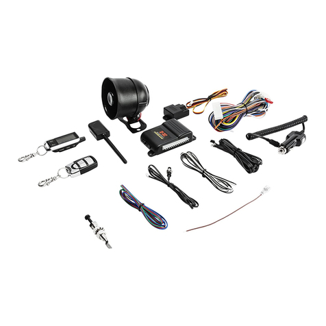
CS-2004TW1with2-Way AM/FMLEDPager/Remote&1-Way ‘Sidekick’Remote
CS-2004TW2with2-Way AM/FMLCD PagerRemote&1-Way ‘Sidekick’Remote
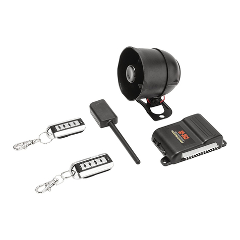
CS-2004DC II withtwo1-Way Remotes
INSTALLATION&OPERATINGINSTRUCTIONS
CONGRATULATIONSon yourchoiceofaSecuritySystembyCrimestopperSecurityProductsInc.Thisbooklet
containsthe information necessaryforinstalling,using,and maintaining your2004TW1/2or2004DC II alarm
system.If anyquestionsarise,contactyourinstallation dealerorCrimestopperSecurityProductsInc.atthe Tech
Supportnumberbelow.
Thisinstallation bookisdesigned forthe installerorindividualwithan existing understanding ofautomotiveelectrical
systems,along withthe abilitytotestand connectwiresforproperoperation.Toeaseinstallation,wesuggestthat
you READTHISMANUALbeforebeginning yourinstallation.Thisbookisprovided asaGENERALGUIDELINE
and the information contained hereinmaydifferfromyourvehicle.
*IMPORTANTINFORMATION:Primaryand OptionalFeatures
-PRIMARY:Thesearefeaturesthatmustbe connected inorderforthe systemtooperateproperlyi.e.Siren,
L.E.D., Power,Ground,DoorPin,Flashing Lightsetc.
-OPTIONAL:Therearefeaturestobe connected onlyifdesired oragreed upon bythe customerand the installing
dealer(i.e.DoorLocks,StarterDisable,Hood/TrunkProtection and AuxiliaryRemoteOutputsetc.).Thesefeatures
mayalsorequireadditionalpartsand/orlaborfees.Consultwithyourinstallerbeforehand tobe sureofwhatis
going tobe installed withyourparticularsystem.
TECH SUPPORT
(800)998-6880
Hours:M-F8:00AM-4:30PM
PacificStd.Time
REV F5.26.2005
ThisdevicecomplieswithFCC Rulespart15.Operation issubjecttothe following two
conditions:1)Thisdevicemaynotcauseinterference,and (2)thisdevicemustacceptany
interferencethatmaybe received,including interferencethatmaycauseundesired
operation.The manufacturerisnotresponsibleforanyradioorTVinterferencecaused by
unauthorized modification tothisequipment. Suchmodification couldvoidthe user's
authoritytooperatethe equipment.
SERIESII

TABLEOFCONTENTS
Installation Cautions&Warnings…….………………………………………………………..…………………………………...………………2
ControlModule/ComponentMounting….………………………..………………………………………………………………….…………..3
Wiring……..…………………………………………………………..……………………………………………………………………………….3-7
PowerDoorLock Wiring...…………………………………….…………………………………..……………..……..…………………………8-9
StarterDisableWiring…………………………..…..………………………………………………………………………………………..……..10
SystemWiring Diagram………………….………………..………………….…………………………………………………………….………11
CS-2004TW1/2AntennaDiagram………...…………………………………………………………………………………….………….…...…12
Option Programming……………..……………………………………………………………..…………………………….……..…….……13-15
ProgrammableOption Reset……………………….....……….…………….……………………………………………….…………………...16
CS-2004TW1/2&CS-2004DCII RemoteProgramming…………………..….…..…………………………………………….…....…….16-17
RemoteOperation………………………………………,…………………….………………..….……………………………………….……...18
Transceiver/PagerRemote……………………………,…………………….………………..….……………………………………….……...19
LowBatteryWarning –LCD Remote……………………………………………………………………………………………………………20
Setting theClock (2-Way LCD Remote)………………………………………………………………………………………………………..20
LCD PanelFunctionsShown..…………………,…………………….………………..….……………………………..……….………….20-21
Operation…………………………………………………,…………………….………………..…………………………………….….……21-24
2VehicleOperation…………………………………,…………………….………………..….…………………………..………….……........25
Carjack Operation…………………………………………………………….…………………..……………………….…..…………………..26
INSTALLATIONCAUTIONS&WARNINGS
BEFOREBEGINNING,check all vehiclemanufacturercautionsand warningsregarding electricalservice(AIR
BAGS,ABS BRAKES,AND BATTERY).
TOPREVENTAPOSSIBLEDEAD BATTERYremovevehicledomelightfusewhileworking on the vehicle.MAKE
CERTAINTOREINSTALL FUSE PRIORTOTESTINGFORDOORTRIGGERS.
DONOTEXCEEDMAXIMUMOUTPUTRATINGS!-SERIOUSDAMAGEMAY OCCUR.LIMITSFORALARM
FUNCTIONSARELISTEDWHEREAPPLICABLE.
2

REMOVE MAINSYSTEMFUSE(S)beforejumpstarting the vehicleorcharging the batteryathigh boost. DAMAGE
MAY OCCUR TOSYSTEMIFPROPERPRECAUTIONSARENOTOBSERVED.
DONOTROUTEANYWIRINGTHATMAYBECOMEENTANGLEDwithbrake,and gaspedals,steering column,
oranyothermoving partsinthe vehicle.
CONTROLMODULE/COMPONENTMOUNTING
DONOTMountthe controlunitorwiring harness inthe engine compartmentoranywheretheycan become
entangled withmoving partssuchasbrake/gas/clutchpedals,orthe steering column.The alarm controlmodule
shouldbe mounted inaconcealed location.The antenna wireshouldbe routed awayfromanymetalifpossible.
Donotalterthe lengthofthe antenna,ground it, orrouteitwithotherwires.
SIRENMOUNTING:Mountthe siren underthe hood tofender-well orotherbodysurfacewiththe open end facing
downward.Run the red siren wirethrough the firewall using arubbergrommet. Ground the black wiretothe body.
LED:Mountthe LEDinavisiblelocation on the dashboardorconsole.
Shock Sensor:Mountthe included shock sensorwithwiretiestoan underdashwireharness orfasten withscrews
tofirewall orside paneling.
Override/ProgramButton:Mountthe Override/Programpush-button inahidden butaccessiblelocation.It isused
foremergency disarm withoutthe useofthe transmitterand forprogramming certainfeatures.
WIRING
REDWIRE:+12VPOWERINPUT(15 AmpFuse)
Connecttoa+12 Voltsourcewiththe supplied fuseand fuse-holder.Werecommend the connection tobe atthe
Vehicle’sBatteryPositiveTerminal.
BLACK WIRE:CHASSISGROUND
THISWIREMUSTBE CONNECTEDTOTHECHASSISMETALOFTHEVEHICLE.Scrape awayanypaintordirt
toensureagood connection.
YELLOWWIRE:IGNITIONSWITCHED“ON”and “START”+12 VOLTS
Connecttoa(+)Ignition wirethatshows+12 Voltswhen the keyisinboththe “ON”and “Cranking”positions.
ORANGEWIRE:(-) NEGATIVE ARMEDOUTPUT
ThiswirebecomesaNegativeGround outputwhen systemisarmed.Thisoutputcan be used foradditionalstarter
disablerelays ortoactivateotherdevicessuchasscannerLED’s,windowmodules,voicemodulesetc.
3

+
+12 V
PINK
OPTIONALCAR JACK WIRING:SWITCH
HIDDENBUTTONor
TOGGLESWITCH
(NotIncluded)
WIRING
WHITEWIRE:+12VFLASHINGPARKINGLIGHTOUTPUT(10A)
Connecttothe switched parking lightwireatback oflightswitchorconnectdirectlytoone ofthe parking lightsatthe
frontofthe vehicle.European vehiclesmayrequireadditionalpartsdue toseparateleft and rightcircuits.
BROWNWIRE:(+)SIRENOUTPUT(3AmpMax.)
Connecttothe siren’sREDwire.Connectthe Siren’sBlack Ground wiretothe chassisclosetothe siren.
BLUEWIRE:(-) HOOD/TRUNK TRIGGER
The Blue wireisused foragrounding hood pinswitch,trunkpinorboth.Connecttoexisting hood and trunkpin
switchesthatread ground when open.If no existing switchesareavailable,install newpinswitchesifdesired.
GREENWIRE:(-) DOORTRIGGER
ConnecttoNegativetype doorswitchesthatread ground when adoorisopened and 12 voltswhen all doorsare
closed.Inthe caseofisolated doortriggers,you mayneed torun additionalwiresfromotherdoorsORgo directly
tothe domelight.
VIOLETWIRE:(+)DOORTRIGGER
ConnecttoPositivetype doorswitchesthatshow+12 Voltswhen the doorisopen and Ground when the doorsare
closed.
PINK WIRE:(+)CARJACK INPUT
Connecttoapushbutton,toggleswitch,ortoa+12
VoltsourcetoselectivelyactivateCarJack protection
features-See diagramon nextpage forexample
wiring configuration.Thiswireisused toactivatea
passivecarjack triggereven ifthe Carjack features
arenotturned on inthe programming options.A
Carjack countdownwill beginunderthe following
conditions:Ignition isON(vehicleisrunning),the
button ortoggleswitchispressed,and adooropens
&closes.Upon these3events,inthatorder,the
alarm will startaCarjack countdown.See “Carjack protection”section on page 19.
4

WIRING
GRAYWIRE:(-) NEG. INPUT[COIL]FORON-BOARD 15ARELAY(Term #85,Step#1)
Thisinputcontrolsthe function ofan on-boardrelay.Connecttoanydesired AuxiliaryorOptionalwirefromthe
Brown3-pinoutputharness.Connectthe Graywiretothe Orange/Black forDomelightillumination,Brown/Black
forAuxiliary1orRed/Black forAuxiliary2function.(See diagram,nextpage)
WHITE/REDWIRE:(+/-) INPUTSOURCEFORON-BOARD 15ARELAY(Term #87,Step#2)
Connecttoa+12 VoltsourceorChassisGround depending on the polarityofthe circuityou aregoing toauxiliary
circuitorfunction you aregoing toactivatewiththe Black/Whiteoutputwire.Connectto+12VforPositiveCircuits
orChassisGround forNegativecircuits.Thiswiremustbe the samepolarityasthe Black/Whitewire.(See
diagram,nextpage).
BLACK/WHITEWIRE:(+/-) OUTPUTFROMON-BOARD 15ARELAY(Term #30,Step#3)
ConnectthiswiretoyourAuxiliarydeviceorFunction.The function ofthisoutputdependson the connection ofthe
Graywireand the polarityofthisoutputmatchesthe White/Red wire.(See diagrambelow)
Orange/Black
Brown/Black
Red/Black
(-) Neg.DomelightIllumination
(-) Neg.AuxiliaryChannel#1
(-) Neg.AuxiliaryChannel#2 ChooseOne
Gray(Term#85)
White/Red (Term#87)+12Vor
Black/White(Term#30)
DomelightIllumination
Aux.#1,Aux.#2 or
15ARelayOutput:
Auxiliary15AOn-Board
relay wiring
INPUT
SOURCE
BROWN/WHITE:(-) HORN HONK OUTPUT(Optional, May requirearelay)
Connecttothe NegativeHornTriggerwireusuallylocated atornearthe steering column.If the vehiclehorncircuit
requires+12V,then arelayisrequired.RELAY WIRING: Connectthe Brown/Whitewiretoterminal85,connect
relayterminals86 and 87 to+12Vconstantpower.Connectterminal30 ofthe relaytothe +12Vpositive
device/circuittobe activated.
5

WIRING
MINIPLUGS:
2-PINPLUG(SMALL): LEDINDICATOR(REDFLASHINGLIGHT)
2-PINPLUG(LARGE): PROGRAM/OVERRIDEPUSHBUTTON
4-PINSENSORPLUG:
REDWIRE:SENSOR+12VPOWER
BLACKWIRE:SENSORGROUND
BLUEWIRE:NEG. WARN AWAY
WHITEWIRE:NEG. TRIGGER
3-PINBLUESENSOR#2 PLUG:(Foradding additional
PIN1:SENSOR+12VPOWERsinglestagesensors)
PIN2:NEGATIVE (-) TRIGGER
PIN3:SENSORGROUND
3-PINBROWNAUXILIARY/DOMEOUTPUTPLUG:
ORANGE/BLACK WIRE:(-) DOMELIGHTILLUMINATIONOUTPUT(Optional)
ProvidesaNegativeOutputfor30 secondsupon disarming oruntil ignition isturned on whichevercomesfirst. Use
thiswireforilluminated entryintoyourvehicle.Connecttothe Graywireifyou choosetousethe on-boardrelay,or
thiswirecan be connected toan externalrelay[ifthe on-boardauxiliaryrelayisbeing used foranotherfunction]. If
using on-boardrelay,see pages4&5,orforexternalrelaysee following information:
Negative DomeLightSystem:Connectstoterminal85 ofarelay.Connectterminals86 +12VConstant.
Connectterminal87 toChassisGround and ConnectTerminal30 tothe Negativedomelightactivation circuit.
Positive DomeLightSystem:Connectstoterminal85 ofarelay.Connectterminals86 &87 to+12Vfused
Constant. Connectterminal30 tothe Positivedomelightactivation circuit.
NOTE:DomelightIllumination cancelsthe activerearm feature.
TIP:The Sensorsupplied with
thissystemdoesnotrequire
anyadditionalwiring,simply
mountthe sensorinasuitable
location,plug in,and adjustto
the desired levelsof
sensitivity.The Black dialis
forPre-warnleveland White
dialisforShock trigger.
6

WIRING
BROWN/BLACK WIRE:(-) AUX.OUTPUT#1 ORM.A.P.-MobileAccessories Protection (Optional)
Thisisaprogrammableoutputwirethatcan operatetwodifferentways:
1.(DEFAULTOperation)ARemoteAuxiliaryOutputthatprovidesa½Second (-) Negativepulsewhen Button
#3 ispressed and released toopen apowertrunkorhatchrelease.Connecttothe Brown/Black wireifyou
choosetousethe on-boardrelay,orthiswirecan be connected toan externalrelay[ifthe on-boardauxiliary
relayisbeing used foranotherfunction]. If using on-boardrelay,see pages4&5,orforexternalrelaysee
following information:ConnectBrown/black toterminal85 ofarelaytooperateAUXdeviceorfunction.
Connectterminal86 orthe relayto+12 Voltsconstant. Connectterminal87 to+12VoltsorGround depending
on the type ofcircuitneeded.UseTerminal30 toactivatethe AUXfunction ordevice.
2.(MAP Operation)Providesacontinuous(-) Negativeoutputwhen the alarm systemisputintoVALETPARK
MODE.Thiscan be used tointerruptthe accessorywireofthe vehicle,preventing unauthorized useofthe
vehicle’saudioorentertainmentsystemswhen VALETPARKMODEisON,hencethe name“MAP –Mobile
AccessoryProtection”.
86 85
87
3087A
START
IGN
ACC
OFF
FM
105.5
wireofmobileaccessoriessuchasAudiosystem
Connectrelayasshowntointerruptthe power
RADIO,etc.
Brown/Black MOBILEACCESSORYPROTECTION
orVideo monitors.The Alarmwill disconnect
theseaccessorieswhen inVALETPARKMODE.
CUT
Relaynotincluded
KEY
SIDE
WHITE/REDWIRE:(-) REMOTEOUTPUT#2 (Optional)
Thiswireprovidesamomentary(-) NegativeauxiliaryOutputwhen Button #4 ispressed and heldforatleast2
seconds.Connecttothe Graywireifyou choosetousethe on-boardrelay,orthiswirecan be connected toan
externalrelay[ifthe on-boardauxiliaryrelayisbeing used foranotherfunction]. If using on-boardrelay,see pages
4&5,orforexternalrelaysee following information:Connectthiswiretoterminal85 ofarelaytooperatean AUX
deviceorfunction.Connectterminal86 orthe relayto+12 Voltsconstant. Connectterminal87 to12Voltsor
Ground depending on the type ofcircuitneeded.Useterminal30 toactivatethe AUXfunction ordevice.This
outputismomentaryand will stayactiveaslong asthe transmitterbutton ishelddown.
7

POWERDOORLOCK WIRING
6-PINDOORLOCK PLUG18 GA.(Optional/ON-BoardRelays):
VIOLET:DOORLOCK Relay Term.#87:NormallyOpen [PolarityInputforLock relay]
WHITE:DOORLOCK Relay Term.#30:Common [Lock Output]
GRAY:DOORLOCK Relay Term.#87A:NormallyClosed
VIO/WHT:DOORUNLOCK Relay Term.#87:NormallyOpen [PolarityInputforUnlock relay]
GREEN:DOORUNLOCK Relay Term.#30:Common [Unlock Output]
BLUE:DOORUNLOCK Relay Term.#87A:NormallyClosed
DETERMININGDOORLOCK TYPE:Werecommend determining the type oflocking systemthe vehiclehas
beforeconnecting anywires.Incorrectconnection mayresultindamage tothe alarm and/orvehiclelocking system.
Thisdoorlock information isprovided asaguide.Yourvehiclemaydiffer.
Negative Trigger(-): ManyImports;LatemodelFord&GeneralMotors
Negativetriggerdoorlock systemssend aNegative(Ground)pulsetoexisting factoryrelays tolock and unlock the
vehicledoors.
Positive Trigger(+): ManyGeneralMotors;Chrysler/Dodge/Plymouth
Positivetriggerdoorlock systemssend aPositive(+12V)pulsethrough factoryrelays tolock and unlock doors.
Reverse Polarity:ManyFord/Lincoln/Mercury/Dodge/Chrysler/Plymouthand early90’sGMTrucks
ReversePolaritysystemsuseno relays,butinstead the doorlock/unlock motorsarecontrolled directlyfromthe lock
and unlock switchesinthe door.The lock and unlock wiresrestatNegativeGround when notinuse.When the
lock orunlock button ispressed,one ofthe circuitsis“Lifted”and replaced with+12Vcausing alock orunlock.
SingleWire(DualVoltage): LatemodelChrysler/Dodge/PlymouthVehicles,some2000-UPGM
DualVoltage systemshavelock/unlock switchesthatsend varying amountsofPositivevoltage ORNegativeground
currenttothe SAMEwireforbothlock and unlock.When the vehicle’sBodyComputerModule(BCM) ordoorlock
modulesensesdifferentvoltageson thiswire,the systemwill eitherlock orunlock.Singlewiredoorlock systems
requirerelays and resistors.
DatabusSystems(2003 GMTrucks &SUV’s,‘99-04 JeepGrand Cherokee)
Databussystemssend lowcurrent“Datamessages”tothe doorlock controllersinordertolock and unlock the
vehicle.Toinstall aftermarketsystemsinthesevehicles,an interfacemoduleisrequired thatconvertsthe regular
lock/unlock pulsesinto“Datamessages”toallowlocking &unlocking.Interfacemodulesaresoldseparately.
8

POWERDOORLOCK DIAGRAMS
UL
REVERSE POLARITYDOORLOCK WIRING
+
L
NEGATIVE TRIGGERDOORLOCK WIRING
UL
L
NOTUSED
UNLOCK WIRE
CUT
LOCK WIRE
CUT
FACTORY
LOCKING
RELAYS
UL
L
+
AFTERMARKETMOTORDOORLOCK WIRING
UL
L
POSITIVE TRIGGERDOORLOCK WIRING
FUSED
+12V+
UNLOCK WIRE
LOCK WIRE
FACTORY
LOCKING
RELAYS
X=
BLUE
GREEN
GRAY
WHITE
VIOLET
VIOLET/WHITE
X
X
NOTUSED
X=
BLUE
GREEN
GRAY
WHITE
VIOLET
VIOLET/WHITE
X
X
FUSED
+12V
BLUE
GREEN
GRAY
WHITE
VIOLET
VIOLET/WHITE
FUSED
+12V+
BLUE
GREEN
GRAY
WHITE
VIOLET
VIOLET/WHITE
UNLOCK WIRE
LOCK WIRE
9

STARTERDISABLEWIRING
STARTERDISABLEPLUG:(3)ORANGE14 GA.WIRES:
(PROGRAMMABLE:NormallyClosedorNormallyOpenConfiguration withON-BoardRelay)
Note:READ BELOWbeforeconnecting starterdisable!NormallyOPENmustbeprogrammedtooperate.See pg 13.
NormallyClosedStarterdisableisthe standardtype used withmostalarm systemstoday.Thiscircuitwill disablethe
Starterwhilethe alarm isarmed orhasbeen triggered.If 12Vpowerisremoved fromthe systemorthe Batterygoesdead,
the relaywill revertback tothe closed position.(FactoryDefault)
NormallyOpenStarterDisableisaHigh-Securitycircuitthatwill disablethe starterwhilethe alarm isarmed ortriggered
AND ifthe unitisunplugged orremoved frompower.Thismeansthatifthe vehicle’sBatterygoesdead orthe unitis
unplugged fromthe vehicle,the carwill still notstart. Weonlyrecommend thistype ofcircuitifyou can install ahidden high-
currenttoggleswitchtodefeatthe NormallyOpen disableincaseofadead batteryorifthe unitisunplugged/removed for
service.(Togglenotincluded)See programming option #13 on page 13 toenablethistype ofstarterdisable.
CUT
STARTWIRE
STARTER
ORANGE
IGN
SWITCH
ORANGE
ORANGE
N/C
N/O
COM
NOTEALIGNMENTOFPLUG
N/C=NORMALLYCLOSED
NORMALLYCLOSEDSTARTERDISABLE(DEFAULT)
CUT
STARTWIRE
STARTER
ORANGE
IGN
SWITCH
ORANGE
ORANGE
N/C
N/O
COM
NOTEALIGNMENTOFPLUG
N/O=NORMALLYOPENHIDDENTOGGLE
SWITCH
**JUMPER#7 MUSTBE
REMOVED!** (NOTINCLUDED)
NORMALLYOPENSTARTERDISABLE(OPTIONAL)
1
0

SYSTEMWIRINGDIAGRAM
IGNITION
STARTER
SWITCH
PARKING
LIGHTS
(+/-) On-BoardRelay
BATTERY
-
BLACK/WHITE
15AOn-board
WHITE/RED
GRAY
CUT
IGNITION
+
SWITCH
+CAR-JACK ENABLE
OUTPUT
(-)HOOD/TRUNK TRIGGERSWITCH
SIREN
(-) ARMED
(-)DOORTRIGGERSWITCH
+DOORTRIGGER
PINK
VIOLET
FUSE
POLARITYSELECTUNLOCK(87)
GREEN
POLARITYSELECTLOCK(87)
BLUE
UNLOCK OUTPUT(30)
Siren+2AMAX
BROWN
UNLOCK SWITCH(87A)
LED
BATTERY+
LOCK SWITCH(87A)
+10AMAX
RED
WHITE
+SWITCHEDIGN"ON"
LOCK OUTPUT(30)
(-) 500MA
ORANGE
YELLOW
N/O
N/C
BLACK
GROUND VALET/PROGRAM
SWITCH
VIO/WHT
COMMON
VIOLET
WHITE
GRAY
GREEN
BLUE
N/O
N/C
SHOCK SENSOR
DUAL-STAGE
SENSOR2
OPTIONAL
CS-2004DC
CS-2004TW1
CS-2004TW1/2Antenna
BLACK 3-PIN
BROWN/WHITE
(-)HORN
OUTPUT
PORT
Series II
(-) REMOTE
OUTPUT2
RED/BLACK
(-) REMOTE
OUTPUT1
BROWN/BLACK
(-) DOMELIGHT
ILLUMINATION
ORANGE/BLACK
relay output(30)
inputsource (87)
On-boardrelay
coil input(85)
CS-2004TW2
11

CS-2004TW1/2ANTENNA
The following diagrampertainstothe CS-2004TW1/2two-waypaging modelonly:
WINDSHIELD
ANTENNA
LOCATIONS
CS-2004TW1
Black Plug
WhitePlug
RECOMMENDED
NoteOrientation ofBlack &
WhitePlugs.Colorsmust
match,orsystemwill not
operate!
TransceiverBox&Antenna
CS-2004TW1/2AntennaSystem
CS-2004TW2
CS-2004DCII
12

OPTIONPROGRAMMINGSoft.686/697
You can programeachoption individuallyormultipleoptionsinone session.You maystartwiththe lowestoption #
and continue on tohigheroptionswithoutrepeating the steps#1 through 3.
To EngageOption Programming:
1.TurnKeytothe ONposition.
2.Press program/valetbutton 5times,afterafewsecondsthe unitwill flashthe lights5timesand the LEDwill
lightsolid.
3.Pushthe valet/programbutton [again]the numberoftimesthatcorrespondstothe option numberdesired (1thru
16).Press sothatyou getalightflashaftereachbutton press.If the unitdidnotflashthe lights,then itdidnot
registeryourpress.See chartbelowforoption list.
4.When you reachthe desired programming level,Press button #1(Lock)or#2 (Unlock)tochange the option.
Pressing button 1will provide one lightflashand pressing Button 2will provide 2lightflashes.
5.TurnIgnition OFF and check forchanged features.Change eachoption individuallyrepeating steps#1-5.
*=FactoryDefaultValues
Option #Option Description Lock Button #1 Unlock Button #2 TXButton #3
1Autolock withIgnition OFF *ON
2PassiveArming ON*OFF
3ActiveRe-Arm ON*OFF
4PassiveLocks ON*OFF
5Parking Lightson w/Disarm OFF *ON
6Brown/Black wireFunction M.A.P.
(ValetPark)*TrunkPop
(Aux.#1)
7Type ofCarjack protection:
ActiveorPassiveCarjack Passive*Active
8Disarm on Trunkpop OFF *ON
9Open DoorWarning 5Sec.*60 Sec.
10 DoorLock PulseTime3Sec.*0.75 Sec.
11 DoubleUnlock Pulse2Pulses*1Pulse
12 Enable/DisableCarjack FeaturesEnable*Disabled
13 StarterDisableRelayConfig.NormallyOpen *NormallyClosed
14 Ignition Arm /Disarm ON*OFF
15 FactoryHornChirp/PulsesPulsewithTrip
OnlyArm/Disarm Chirps
&Pulsew/Trip*Arm/Disarm/
WarnChirps&
Pulsew/Trip
16 Option resetResetoptions
13

OPTIONPROGRAMMING
1.AUTOLOCK WITHIGNITION
Thisoption controlswhetherthe doorswill automaticallylock when the ignition isturned on and will unlock when the
ignition isturned off.
2.PASSIVE ARMING
Thisoption controlsthe Passive(Automatic)arming feature.If ON,arming will occur30 Secondsafterthe ignition is
turned off and the lastdoorhasbeen closed.The LEDwill beginflashing rapidly.If adoorisreopened,the system
will wait(LEDsolid)forthe doororzone toclosebeforearming.
3.ACTIVE RE-ARM
ActiveRe-arming allowsthe systemtore-arm itself30 secondsafterdisarmed withthe transmitterifadoorhasnot
been opened.Thisishandyifthe vehicleisaccidentallydisarmed withoutyourknowledge.Note:Activere-arm is
resetbydomelightillumination.
4.PASSIVE LOCKS
Thisoption controlswhetherthe doorswill alsolock when PassiveArming occurs.Note:Mayincreasethe risk of
locking keys inthe vehicle.
5.PARKINGLIGHTSONWITHDISARM
Keepsparking lightson when systemisdisarmed toassistinlocating and providing illumination nearyourvehicle
when approaching atnightforsafety.
6.GRAYWIREPROGRAMMING:TRUNK POP(AUX1)orM.A.P.OUTPUT
Thisoption controlswhetherthe system’sGRAY wirefunctionsasRemoteAux.Output1,orasan Outputfor(MAP)
MobileAccessoriesProtection.Mobileaccessoryprotection activatesonlyinValetParkMode.See page 7.
7.TYPE ofCARJACK PROTECTION(ACTIVE orPASSIVE)
Thisfeaturecontrolsthe type ofCarjack protection the alarm will provide.Selecting Button 1(Lock)providesActive
protection using the remotecontrol,orselecting Button 2(Unlock)providesPassiveprotection thatoccurswhen a
dooropensand closeswiththe Ignition on.Option #12 mustalsobe enabled toallowCarjack featurestooperate.
8.DISARMWITHAUX.OUTPUT1(TRUNK POP)
Controlswhetherthe systemwill orwill notDISARMwhen the trunkpop orAUX1.featureisused.When this
option isturned on,the unitwill DISARMwhen opening trunkorusing an auxiliarydevicecontrolled bythe Trunk
button.
14

OPTIONPROGRAMMING
9.OPENDOOR/ZONEWARNING(5or60 Seconds)
Thissetting changesthe delaytimeinwhichthe alarm systembeginstomonitorthe DoorZone.Thisishelpfulon
vehicleswithdelayed domelights.It preventsthe alarmswarning chirpsdue toextended domelightcircuit.
10.DOORLOCK/UNLOCK PULSE TIME
Controlsthe amountoftime(0.75 sec.or3sec.)forthe lock/unlock pulse.The 3sec.setting maybe required for
1980’/90’sEuropean Vehiclesthatrequirealong pulsetooperateVacuumdoorlock systems.
11.DOUBLEUNLOCK PULSE
Thisoption controlswhetherthe unitwill send one ortwounlock pulseswhen disarmed.Thisfeaturemaybe
required forinterfacing toexisting FactoryKeyless EntryorAlarm systemsinavehicle.Thesesystemsarefound
on someNissan,VW,Toyota,and Lexusvehicles.
12.ENABLE/DISABLECARJACK FEATURES
Thisoption controlsthe unit’sCarJack features.EnableorDisableCarjack (TurnONorOFF)withthisoption.
13.STARTERDISABLECONFIGURATION:NORMALLYCLOSEDORNORMALLYOPEN
Thisoption controlsthe unit’son-boardStarterdisablerelayforeither“NormallyOpen”or“NormallyClosed”
operation.See page 10 formoreinformation.
14.IGNITIONONARM/DISARM
Thisoption controlwhetherthe unitwill allowarming and disarm using the remotewhen ignition inON(orvehicleis
running).Thisprogramoption mayneed tobe ONwhen using an add-on remotestartertoallowthe alarm tobe
armed ordisarmed afterthe remoteengine starts.Notethatyou cannotusethisfeatureifyou arealsousing the full
timecarjack protection.If you add aremotestartand the ignition isturned ON,acarjack triggerwill be activated.
15.FACTORYHORN CHIRP/PULSE
Thisoption controlsthe system’sfactoryvehiclehornoutput. Thereare3selections.Button 1(lock)=hornpulse
onlywhen an alarm istripped.Button 2(unlock)=hornchirpsforarm/disarm and pulsewhen tripped.Button 3
(trunk)=hornchirpsforarm/disarm and pre-warning protection pulseswhen triggered.
15

PROGRAMOPTIONRESET
Thissystemprovidesa“resetmethod”torestoreall optionstoFACTORYDEFAULTVALUES aslisted inthe
“Button #2”columnofthe programmableoption charton page 13.Thiscan be helpfulifyou havelosttrack ofthe
option settingson yoursystemorwhen you aremoving systemsfromcartocar.
1.TurnKeytothe ONposition,wait5seconds.
2.Press program/valetbutton 5times,afterafewsecondsthe unitwill flashthe lights5times.
3.Pushthe valet/programbutton 16 times.Press button carefully.You mustgetalightflasheachtimeyou press
the button.If the unitdidn’tflashthe lights,then itdidnotregisteryourpress.
4.Press button #2 (Unlock)toresetthe options.Lightswill flashtwice.
5.TurnIgnition OFF.All featuresshouldbe setat“*DEFAULT”values.
CS-2004TW1/2&CS-2004DC II REMOTEPROGRAMMING
TRANSMITTERPROGRAMMINGNOTES (Readfirst!):
(1)The CS-2004TW1/2will learnup to4remotes,anycombination ofspecialCS-398TW1-wayorCS-899LED2-
waypagerremotesorCS-499LCD 2-waypagerremote..
(2)The CS-2004DC II will up to4CS-404TXremotes.The remotecontrolsforthe CS-2004DC II and the CS-
2004TW1/2systemsARENOTinterchangeable.
RemoteTransmitters/Transceiverscomepre-programmed toyoursystemfromthe Factory.When re-learning remotesoradding remotes,ALL your
system’sremotecodesmustbe learned attimeofprogramming!Thesesystemsallowstorage ofup to4differentremotecodesinmemory.Note
the slightdifferenceinprogramstep #4 foreithera2004DC II ora2004TW1/2system.See stepsbelow.
TRANSMITTERPROGRAMMINGSTEPS:
1.Turnkeytothe ONposition and wait5seconds.
2.Press Programming/Valetbutton 4times.
3.Afterafewseconds,the unitwill flashthe parking lights4times.
4.A.FORCS-2004TW1/2:Press Buttons#1 &2togetheron the remoteyou wishtoprogram.
B.FORCS-2004DC II Press the Button #1 (Lock)on the remoteyou wishtoprogram.
5.You shouldget2lightflashesindication the unitiswaiting fora2nd code,then press buttons#1  ofa
second transmitter,thirdorfourthortransmitterortransceiver.NOTE,the systemwill notflashthe lightsafter
learning the fourthcode.Turnkeyoff toexitprogramming mode.
TRANSMITTERPROGRAMMINGDIAGRAMONNEXTPAGE.
1
6

CS-2004TW1/2&CS-2004DC II REMOTEPROGRAMMING
IGN
OFF
WAITFOR
4FLASHES
PRESS 4X's
FLASH2,3,or4X's
1-WAY(CS-404TX)
IGN
OFF
COMPLETE
CS-2004DC II
SIDEKICK REMOTE(CS-398TW)
PRESS TOGETHER
CS-2004TW1/TW2
CrimeStopper
SLNT
AUX
PRESS TOGETHER
TW2(CS-499LCD)TW1(CS-899LED)
PRESS TOGETHER
PRESS LOCK BUTTON
AUX
CrimeStopper
SLNT
AUX
SLNT
17

OPERATION
CS-2004DC II /CS-2004TW1remotecontrols:
CS-2004TW1TWO-WAYPAGEROPERATION&PAGETONES:
PAGE-BACK:
FEATUREBUTTONACTIONBEEPS LED/FLASH
ARM/LOCK#1 (Lock)Press &Release1X,then 1XagainOrange /1X
DISARM/UNLOCK#2 (Unlock)Press &Release1Xthen 2XagainGreen /2X
PANIC#1 (Lock)Press/hold3sec.1Xthen 2X,12X1XGreen /12XOrn.
SILENTARM#4 (Slnt)Press &Release1Xthen 1XOrange /1X
SILENTDISARM#4 (Slnt)Press &Release1Xthen 2XGreen /2X
AUX#1 #3 (Aux.)Press &Release1Xthen 3XYELLOW/1X
AUX#2 #4 (Slnt)Press/hold2sec.1XNOPAGEBACK
DoorViolation 1Long /1ShortRed /5X
Hood/TrunkViolation 5ShortGreen /5X
Ignition Violation 1Long /3ShortBlue /5X
SensorViolation 1Long /2ShortYellow/5X
Pre-Warning 1Long Yellow/1X
SLNT
#3
#1
#2
#4
LOCK
TRUNK SILENT/
UNLOCK
#5 VEHICLE2
FLASHLIGHT
AUX.#1 AUX.#2
AUX
CS-404.TX/CS-398.TW
CrimeStopper
18
UNLOCK
LOCK
PAGING
LED's
SILENT/AUX2
ANTENNA
FIXED
TRUNK/AUX1
#1 #2
#3 #4
SLNT
#5 2nd VEHICLE
Press Together
CS-899 LED
AUX

BUTTON5(Onsideofremote):
•Press and releasetolightup
the LCD screen.
•Press and releasetwiceto
recall the lastmessage from
the LCD screen.
•Press and Holdtwoseconds
tochange fromCar1toCar2
•Press 5timestochange the
Timeand audiblebeep tones
on the remote.
TRANSCEIVER/PAGER-REMOTE
PAGER/REMOTETRANSCEIVER:
The hand-heldremotetransceiverisused tosend and receive
information fromthe vehicle.The ControlModuletransmitsHigh
Frequency AM/FMsignalsfromthe vehicletoyouroverlong
distances.Yourrange will varydepending on location,terrain,and
localRFnoise/interference.Thissystemisnotguaranteed topage
you ifyou arebehind concretewalls,underground,inalarge
structure,orinan area withhigh levelsofelectronicinterference.
Handlethe pager/remotewithcareifthe LCD displayand/orthe
electronics maybe damaged ifsubjected toabuse.The AAA Cell
1.5Valkaline batterycan easilybe replaced bysliding open the
batteryaccess dooron the back ofthe remote.Batterylifewill vary
depending on usage.The LCD screen will displayalowbattery
icon when the batteryislow.
BUTTON1(Lock Symbol):
•Press and releasetoArm/Lock system.
•Press and Holdformorethan 3secondstoactivate“Panic”feature.
•When ignition on –doorlocks.
BUTTON2(Unlock Symbol):
•Press and releasetoDisarm/Unlock system,orresetacycle.
•When ignition on –doorunlocks.
BUTTON3(TrunkSymbol):
Press and Releasetoactivatetrunkpop (Auxiliaryoutput#1)
BUTTON4(StartKey Symbol):
•Press and releaseforsilentarm/silentdisarm.
•Press and holdformorethan 3secondstoactivateAux#2.
19
CS-499.LCD
#2 DISARM
UNLOCK
LCD
SCREEN
#4 SILENT
#1 ARM
LOCK
#3 TRUNK
#5 RECALL
CAR IorII
FIXED
ANTENNA
AM

1STAUX.OUTPUTTRUNK
POP(FLASH)(ORHOOD
OPEN)
LOWBATTERYWARNING–LCD REMOTE
CS-2004TW1LED&CS-2004TW2LCD (LOWBATTERYWARNING)
The CS-2004TW1LEDand the CS-2004TW2LCD havealowbatterywarning system.When
the batteryvoltage islow,the LEDremotewill stop beeping and flashthe Orange &Green LEDs
6timeswhen buttonsarepressed.The LCD pagerremotewill showalowvoltage icon.We
recommend replacing the batteryforproperoperation.Toreplacethe battery,simplyunlatch
and slide open the batterydooron the back ofthe remote.CarefullyinsertanewAAA battery
using the outline on the bottomofthe batterycompartmentasaguide.Yourremotewill beep 3
timesifthe batterywasinserted correctly.Otherwise,removethe batteryand insertagain.
SETTINGTHECLOCK (2-WAY–LCD REMOTE)
1.Press button #5 (recall)on the side ofthe remotecontrol5times.
2.The remotewill beep and the AMorPMdisplaywill beginflashing.
3.Press button #3 (trunk)togo tothe nextitemAM–PM–Hour–Minutes.
4.Press button #1 (lock)toincreasetime.
5.Press button #2 (unlock)todecreasetime.
6.Press button #4 (start)todisableorenablebeep.
7.Press button #5 (recall)toexitsetup orwait7seconds,the LCD lightwill turnoff.
LCD PANELFUNCTIONSSHOWN:
ARM
DOOROPEN(FLASH)
PANIC(FLASH)
CAR JACK
D
ISARM
20
This manual suits for next models
5
Table of contents
Other CrimeStopper Security System manuals

CrimeStopper
CrimeStopper Cp-4900 User manual

CrimeStopper
CrimeStopper CG-1000 User manual

CrimeStopper
CrimeStopper CS-9705 Owner's manual

CrimeStopper
CrimeStopper SP-302 User manual

CrimeStopper
CrimeStopper RS901 RS900ER User manual

CrimeStopper
CrimeStopper CS-872 User manual

CrimeStopper
CrimeStopper CS-2002DC.IV Manual

CrimeStopper
CrimeStopper SP-101 Manual

CrimeStopper
CrimeStopper CS-2000DPII SERIES IV Manual

CrimeStopper
CrimeStopper SP-102 User manual