Omega Crime Guard 650i6 User manual

05/09 MI-CG-650i6/750i6
BACK COVER
PRINTER’S NOTE:
production back cover
is to be printed with gray
scale front cover; this is a
place marker cover.
Crime Guard
650i6 &750i6
INSTALLATION
INSTRUCTIONS
COPYRIGHT 2009:OMEGARESEARCH&DEVELOPMENT,INC.
FRONT COVER
PRINTER’S NOTE:
production front cover
is gray scale; this is a
place marker cover.

Page - 35
Wiring Diagram Overview ........................................................................... 18-19
Installation Considerations ........................................................................... 3-5
Wiring Connections
Main Wiring Harness ................................................................................... 6-8
Secondary Wiring Harness ........................................................................... 9-17
Auxiliary Harness & Programmable Relays ................................................ 14-16
Accessory Connections
DLS Power Doorlock Port..................................................................... 17, 20-22
Backup Battery ............................................................................................. 23
Dual Sensor Ports ......................................................................................... 23
Data Port ....................................................................................................... 23
Programming
The Programmable Features......................................................................... 24-32
Programming Features ................................................................................. 33
Programmable Features Matrix .................................................................... 34
Contents
Omega Disclaims Any Responsibility or Liability In Connection With Installation.
The Crime Guard 650i6’s transmitters and the 750i6’s 1-way transmitter and
2-way controller are pre-programmed at the factory to operate the system. If
adding or replacingtransmitters or controllers, pleasesee theOperation
Guide booklet for Transmitter and Controller programming.
Copyright2009 OmegaResearchandDevelopment,Inc.

Page - 34 Page - 3
Installation Considerations
Before Starting The Installation: This entire booklet should be read
before starting the installation. An understanding of which control module wires
are to be used and their functions is essential. Installations will vary from car to car
, as some control module wire connections are required, while others are optional.
Before starting the installation, it should be determined which control module
wires will be used. Most installers will list these wires, then "map out" the instal-
lation by locating and noting the target wires in the vehicle. This will also deter-
mine the best location for the control module, which is mounted upon completion
of the installation and testing of the system.
Some of the wiring connections, such as power, ignition and starter interrupt, are
best made at the ignition switch harness, located around the steering column area.
Please carefully read these instructions before
starting the installation of the Crime Guard
security system. The numerous wiring
connections required, and the options offered
by several of the programmable features makes
pre-planning the installation critical.
- IMPORTANT -
More complete instructions for programming
transmitters and features may be found in the
Operation Manual.
Other typical connection points may be behind the dash or in the kick panel areas,
for parking and/or interior lights, trigger circuits and power doorlocks. Soldering
or proper use of crimping terminals for all wiring connections are recommended.
CAUTION! Avoid the Airbag circuit! Especially avoid any har-
ness or wires encased in Yellow or Red tubing or sleeves. Do not
use a standard test light, as it can deploy an airbag or damage
on-board computers and sensors if the wrong circuits are probed.
A Digital Multimeter (DMM) should be used.
Complete Programmable Features Matrix
Features Ignition on, off, then press Valet Switch 5times (Status Light turns on steady).
# Feature Default Setting Option 2nd Option 3rd Option
1 SecureCode 1 & 0 2 stages, of up to 9 presses each (total of 99 possible combinations)
2 Last Door Arming OFF (L) ON w/o doorlock (U) ON w/ doorlock (2)
3 Automatic Rearming OFF (L) ON w/o doorlock (U) ON w/ doorlock (2)
4 Starter Interrupt Functions Alarm only (L) Off(U) Automatic (2)
5 Ignition Activated Override OFF (U) ON (L)
6 Doors Lock With Ignition On ON (L) OFF (U)
7 Doors Unlock With Ignition Off ON (3) OFF (L) o/p 1 only (U) o/p 2 only (2)
8 Open Door Bypass to above ON (L) OFF (U)
9 Confirmation Chirps ON (L) OFF (U) exc. Valet (2) Valet only (3)
10 Confirmation Chirp Volume Medium Loud (2) Low (L) Med Lo (U) Loud (3)
11 Activated Alarm Cycle 30 Seconds (L) 60 Sec. (U) 90 Sec. (2) 120 Sec. (3)
12 Lights On Upon Disarm ON (L) OFF (U)
13 Disarm Upon Trunk Release ON (L) OFF (U)
14 Arming Delay 3 Seconds (L) 15 Seconds (U) 30 Seconds (2) 45 Seconds (3)
15 Steady Siren / Pulsed Horn Steady Siren (L) Pulsed Horn Lo (U) Pulsed Med. (2) Pulsed Hi (3)
16 Alarm Functions Bypass OFF (U) ON (L)
17 Ignition Anti-Carjacking OFF (U) ON (L)
18 Door Anti-Carjacking OFF (U) ON (L)
19 Remote Anti-Carjacking OFF (U) ON (L)
20 Open Door Warning atArm OFF(U) ON(L)
21 III Button Operation
3rd Chan. (L) Panic (U) 4th Chan. (2) 5th Chan. (3)
22 Doorlock Functions .8 second (L) 3 Seconds (U) Double Unlock (2) Total Closure (3)
23 Lock Relay Functions Lock (L) Parking Light (U) Channel 4 Latch (2) Channel4OnDemand (3)
24 Unlock Relay Functions Unlock (L) Horn, med (U) Channel 5 Latch (2) Channel5On Demand (3)

Mounting The Control Module: The Control Module contains the
necessary electronics required for the system's operation. Always mount this mod-
ule in the vehicle's interior compartment, in a secure location that is not easily
accessible. Ensure that moisture, vibration and temperature extremes are mini-
mized. Acceptablelocationsincludemountingbehind the dash, behind the glovebox
or other interior panels.
Mounting The Electronic Siren: The electronic “2-n-1 Psycho Siren”
must be mounted external to the vehicle, but not accessible or vulnerable to tam-
pering. The engine compartment typically offers the best mounting location op-
portunities. See page 9 for specific mounting and connection details.
The Status Light and Valet Switch are in two forms:
- contained within the 2-way transceiver unit, as with the 750i6;
- and as separate items, which can be mounted independently or in a combination
holder, as with the 650i6.
The separate Status Light andValet Switch may be used with the 750i6as optional
parts, and the transceiver unit hidden, if desired; and similarly the 650i6may be
upgraded to 2-way operation, which adds the transceiver to the system. It is im-
portant to understand this flexible compatibility, both ways, between the two se-
curity systems, and with the two forms of Status Light and Valet Switch.
Transceiver- Using the transceiver-mounted items requires no special in-
stallation considerations; this places the Status Light in a good position to be seen,
both inside and outside of the vehicle, and the Valet Switch at a convenient loca-
tion to the user. The user may customize the switch presses required to perform an
Emergency Override with Programmable Feature #1 (the factory setting is the
most convenient “1 press”).
The transceiver unit may be mounted directly to an interior glass by utilizing
the attached adhesive pad (clean and prepare the glass before adhering). The best
operating range performance is obtained by mounting the transceiver placed as
high as possible in the vehicle, with the smaller rod-like end pointed upwards.
Avoid mounting this unit close to metal parts or structure of the vehicle.
Separate- In the case of the 650i6, or as optional parts for the 750i6, the
separate Status Light and Valet Switch may be custom-mounted inside the vehicle
by drilling a 9 / 32” hole in a suitable interior panel; be sure to carefully ensure that
the area behind the location has an unobstructed depth of at least 1/2”. Then route
the wiring harness through the hole to the control module, and snap the light in
place. Mount the valet switch, using its adhesive pad, in a hidden location which
is accessible to the operator; carefully route the wires to the control module.
Or, use the combination holder for the Status Light and Valet Switch. Mount
the assembly in a location where it can easily be seen by the driver, and preferably
where it can be seen from outside. Two mounting methods are provided: double-
Page - 4 Page - 33
Programming Features
Step 7 Allow 10 seconds to pass without performing any programming
actions, or turn the vehicle’s ignition on.
Exit Programming mode:
• The siren will sound briefly and the Status Indicator Light will go out.
Step 6 If there are more features to be programmed, within 10 seconds of
the previous action Press & Release the Valet Switch the same
number of times as the next desired feature’s number.
• Again the siren will chirp and the Status Indicator Light will flash as many
times as the Valet Switch was pressed to indicate the new feature number
which is now accessed. Then use the controller or transmitter as described
in Step 5 to change the newly accessed feature as desired.
To Access and Change further Features:
Step 5 After accessing the desired feature, within 10 seconds Press &
Release the appropriate controller or transmitter button.
• Pressing the “arm/lock” button typically turns the feature on; or sets the
feature’s first option. The siren will chirp once when this button is pressed.
• Pressing the “disarm/unlock” button also typically turns the feature off;
or, sets the feature’s second option. The siren will chirp twice.
• Many features have third, and even fourth setting options. Pressing the
“II” and “III” buttons select these options. Confirmation chirps when
these buttons are pressed are three and four chirps respectively.
Change the Feature:
Step 4 Within 10 seconds, Press & Release the Valet Switch the same
number of times as the desired feature’s number.
•The siren will chirp and the Status Indicator Light will flash off the same
number of times as the Valet Switch was pressed to indicate the feature
number accessed.
Access a Feature:
•The siren will chirp then sound briefly and the Status Light will light
steady to confirm that the system is entering Programing Mode.
Step 3 Within 5 seconds, Press & Release the Valet Switch 5times.
Step 2 Turn the ignition off.
Step 1 Turn the vehicles’s ignition on.
Enter Programming mode:

pressing the “arm/lock” or “disarm/unlock” button. Only the output itself
will stop- pressing either button again will normally operate the system, and at
any time after the 28 second lock output period ends.
If either of the programmable relays are set for lock or unlock operation (the next
two Programmable Features), the settings if this feature will operate the program-
mable relays accordingly, in addition to the primary system doorlocking outputs.
Feature #24 Unlock Relay Functions
Factory Default Setting Door Unlock Output
(press “arm/lock” button to program)
Options:
Horn Output (press “disarm/unlock” button to program)
Channel 5 Latch Output (press “II” button to program)
Channel 5 On Demand Output (press “III” button to program)
This is the second of two built-in relays which can be programmed to perform
several different functions. As described above for the “lock” relay, the primary
function of this second relay is the “unlock” function, which in many cases is not
required and making the relay available for other uses. In the case of this relay, a
verypopular application is operatingthe vehicle’s existing horn; eitherin conjunc-
tion with the electronic siren, or in place of the siren. Using both the siren and the
horn creates an extremely effective security system. The remaining options are
Channel 5, with the same operation parameters as described above for Channel 4.
See the wiring instructions on pages 14-17 for additional details.
Feature #23 Lock Relay Functions
Factory Default Setting Door Lock Output
(press “arm/lock” button to program)
Options:
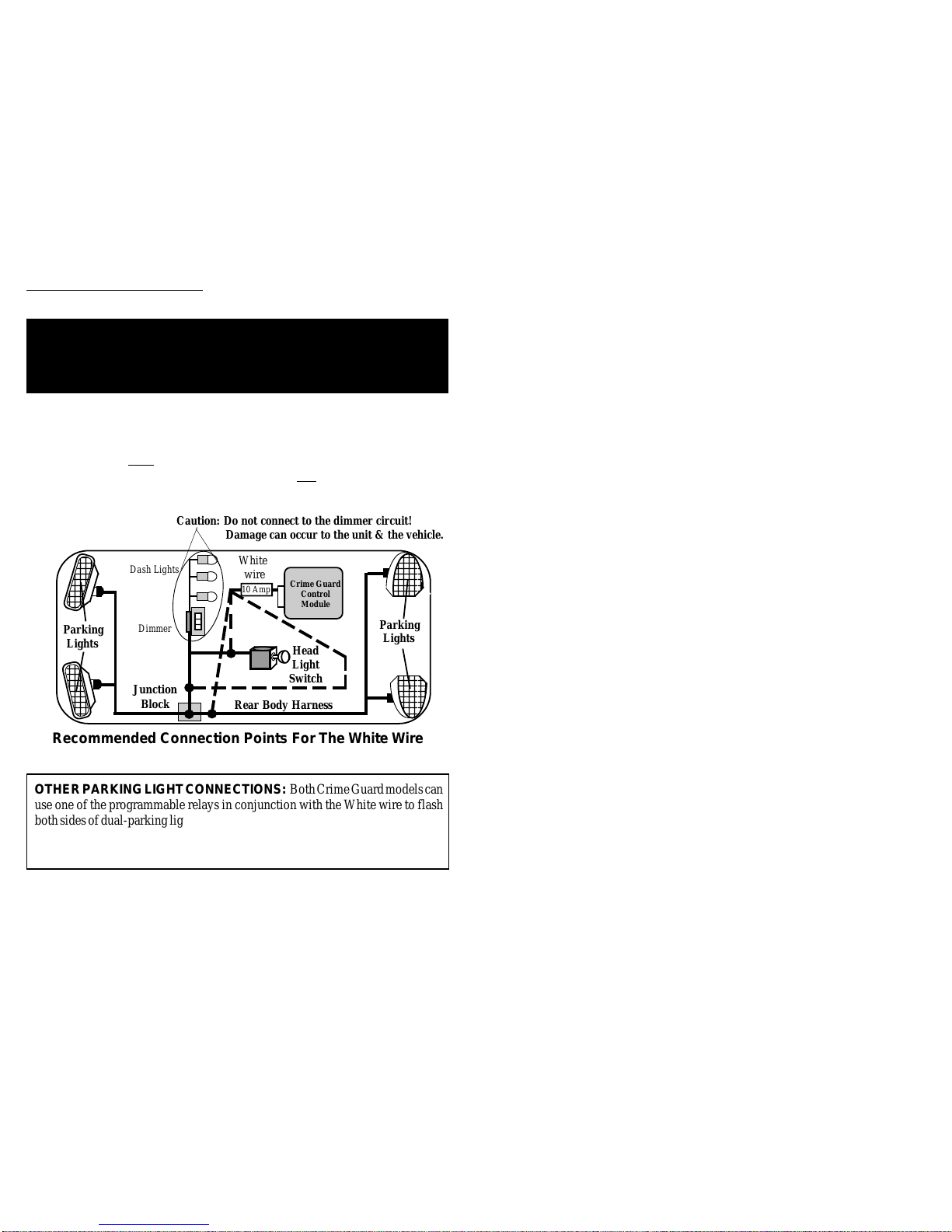
Parking Light Output (press “disarm/unlock” button to program)
Channel 4 Latch Output (press “II” button to program)
Channel 4 On Demand Output (press “III” button to program)
Both Crime Guard models have two built-in relays, which can be programmed to
perform several different functions. Although the primary function, or default
setting, of this relay is to operate as a door “lock” function, there are many vehicles
which don’t actually require a relay in which case the relay is available for the
optional functions. Other options for this relay are parking light flash, which has
the same operation as the White wire, and an additional remote output, operated by
the controller/transmitter’s “arm/lock” and “II” buttons together, and in two
forms: “Latch”, in which the output toggles with each buttons press, and “On
Demand” which is output while the buttons are being pressed. Feature #21 can
change this channel’s button assignment, and see more details on this relay’s total
functions, in the wiring instructions found on pages 14-17.
Page - 32 Page - 5
Power Doorlock Options: The unique flexibility of the 750i6and 650i6
is also found in multiple options for interfacing the vehicle power doorlocks.
InternalRelays- Bothmodelsfeatureinternalrelays,whichareprogrammable
for several different functions. Thee default settings are “lock” and “unlock”, with
optional operations consisting of parking light, horn, or two additional remote
channels, as latching or on demand. Relays are not always needed for doorlock
connection, and the following two options offer further flexibility that the internal
relays can be available for optional functions.
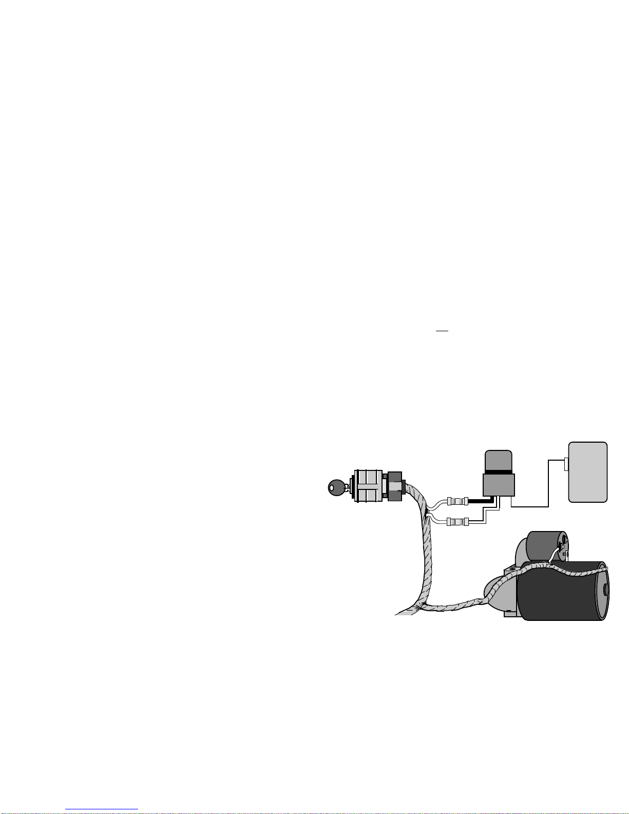
DLS Port- The second option is the traditional “DLS” port, which can accept
allOmegaanalogdoorlockingaccessories(dual,triplerelaysockets,orthemodular
clip-onadd-onrelaypacks)anddirect-wirebasic3-wireNegativepulsedoorlocking
systems. All Omega doorlocking data bus module accessories can be driven by
eitherthisport, and theDLSportoffers two unlockingoutputs,sothat driver’s door
priority unlocking can be configured.
DataPort forIntelliKit Modules & Bypasses: Omega IntelliKit data bus
interface modules and bypass kits simply plug into this port. These data-to-data
(D2D) accessory products save time, and in many cases offer the only acceptable
interfacemeansfor manynewervehicle’sdoorlockingsystem and/orfortheOEM-
antitheftbypasswhenaddinganalarmoranoptionalaccessoryremotestartmodule
with the Crime Guard. Omega offers the industries most comprehensive line of
these products (go to www.caralarm.com for latest application guide), and each
includes its own vehicle-specific instructions.
Backup Battery: Both models have backup battery capability. Included
are the 9 volt battery, the wiring harness and slide-on clip mounting bracket. If the
system loses vehicle power it will revert to operating with basic security functions,
if the backup battery is installed.
Dual Auxiliary Sensor Ports: Both models also feature two auxiliary
sensorports. Theincluded impactsensorplugsintooneport,and thesecondallows
the easy addition of a further optional sensor. Each of the ports is dual-zoned: the
first zone will respond by chirping the siren only; and the second zone will fully
triggerthesystem,andbothhaveidenticallayoutandoperation. Theincludedglass
breakage and dual-zone impact sensor is packaged with its own instruction sheet,
as are all of the optional Omega sensors which can be further added.
sided adhesive tape, and two screws. If using the adhesive tape, properly prepare
the mounting surfaces to ensure good adhesion. If using the screws for a more
permanent mounting, carefully separate the housing halves, install the screws
(avoid overtightening), then snap the assembly halves back together. Carefully
route the wiring harness to the control module to avoid any chances of it being
chafed or pinched.

Wiring Connections
The following sections detail connections for each wire, of
each system’s wiring harnesses. Always insure that the
Black ground wire is grounded, and that the secondary
wiring harness is plugged in, before connecting power
circuits to the control module. The best installation proce-
dure is to make all connections, and only then plug the
individual wiring harnesses into the system control module.
- NOTE -
Page - 6
Main Wiring Harness
(5-Wire Connector)
Red Wire - (Constant Power Input): The Red wire's function is to
supply Constant Positive 12 Volts for security system's operation. When 12 Volts
is first applied to the Red wire, the system will revert to the state in which it was in
when power was taken away. If the vehicle to be serviced, especially if it involves
thebattery,thesystemshouldbeplacedinValetMode. Thiswillpreventthesystem
from being activated if the battery is disconnected and reconnected. The Red wire
alsosupplies12VoltPositivetothemodule'sinternal relay for flashing the parking
lights.
CONNECTION: Connect the Red wire to a Constant Positive 12 Volt source.
ThissourceshouldhavePositive12Voltswithatleasta15Ampcapacityatalltimes
and in all ignition key positions. Connection locations can be at the supply wire at
Black Wire - (Ground): The Black wire provides Negative ground for
the system; proper connection of this wire is very important.
CONNECTION:Usingthecorrectlysizedcrimp-on ringterminal,connectthe
Black wire to the metal frame of the vehicle, preferably using an existing machine-
threaded fastener. Make sure that the ring terminal attached to the Black wire has
contactwithbright,cleanmetal. Ifnecessary,scrapeanypaint,rustorgreaseaway
from the connection point until the metal is bright and clean. If the control module
has an insufficient ground connection, the security system can find partial ground
through the wires that are connected to other circuits, and function, but not
correctly. Asthesystemcan partially operate,abadgroundwireconnection would
not likely be suspected, and in many cases a poor ground is difficult to diagnose.
Options:
Panic (press “disarm/unlock” button to program)
4th Channel (press “II” button to program)
5th Channel (press “III” button to program)
This feature changes how the controller’s or transmitter’s “III” button operates.
Normal operation, or the default setting, has the “III” button operate the Panic
feature. This feature allows changing it to instead operate the 3rd channel or either
of the two other optional channel outputs. Panic can still be operated, by the
alternativemethodsofpressingeitherthe“arm/lock”and“disarm/unlock”button
for 3 seconds.
Page - 31
Feature #22 Doorlocking Functions
Factory Default Setting .8 Second Lock & Unlock Output
(press “arm/lock” button to program)
Options:
3 Second Lock & Unlock Output (press “disarm/unlock” button to program)
Double Pulse Unlock Output (press “II” button to program)
Total Closure Lock Output (press “III” button to program)
This single feature gives the installer several needed options, to match the security
system’s doorlocking outputs to suite different vehicle requirements.
• The first setting (programmed by the “arm/lock” button) has the system
produce both the lock and unlock outputs as .8 second in duration. This is the
most common form of output needed, which interfaces most vehicles.
• The second setting (programmed by the “disarm/unlock” button) changes the
lockandunlockoutputsto be a longer3secondpulseoutput. Thisisforcertain
vehicles which require a longer output pulse from the system’s control unit;
typicallycarshavingvacuumpump systems, althoughthelongersettingisalso
more suitable in some newer vehicles.
• Somenewervehiclesrequireadoublepulseoutputtoremotelyunlockthedoors
and/or to disarm a factory-equipped security system, which is what the Double
Pulse Unlock setting provides (it is programmed by the “II” button ). The lock
output pulse, in this setting, is .8 second.
• The Total Closure Lock Output (programmed by the “III” button) may be used
with vehicles which are originally equipped with the total-closure feature.
Typically, a total closure feature is when locking the vehicle’s doors if the key
in the door is held to “lock” for a period of time the vehicle will close all
windows and the sunroof, in addition to locking the doors.
Selecting this feature setting changes the system’s door lock output pulse from
a .8 second to as long as a 28 second duration output. The unlock output is 3
seconds in this setting.
Note: When this feature is turned on, during the 28 second period after arm-
ing the system, the lock output can be stopped on demand by the user by

sirenrequires. When programming this feature forusingthe output for the vehicle’s
horn, the optional setting produce pulsed output on the system’s siren wire, in
three different pulse timings, which allow a degree of customizing of the horn’s
sound during the alarm activation.
Page - 30
Feature #16 Alarm Functions Bypass
Factory Default Setting Off (press “disarm/unlock” button to program)
Option: On (press “arm/lock” button to program)
This feature converts the system into a strictly Remote Keyless Entry System by
eliminating all antitheft alarm-oriented operations and features. When this feature
is programmed on, the Crime Guard has remote keyless entry operation only.
Factory Default Setting Off (press “disarm/unlock” button to program)
Option: On (press “arm/lock” button to program)
This form of Anti-Carjacking is initiated by the ignition key being turned on. All
3 forms of Anti-Carjacking protection are described in the Operation Guide.
Feature #19 Remote Activated Anti-Carjacking Protection
Factory Default Setting Off (press “disarm/unlock” button to program)
Option: On (press “arm/lock” button to program)
This form of Anti-Carjacking is initiated by a signal from the controller or
transmitter. All 3 forms of Anti-Carjacking protection are described in the
Operation Guide.
Feature #18 Door Activated Anti-Carjacking Protection
Factory Default Setting Off (press “disarm/unlock” button to program)
Option: On (press “arm/lock” button to program)
This form of Anti-Carjacking is initiated by a door being opened. All 3 forms of
Anti-Carjacking protection are described in the Operation Guide.
Feature #20 Open Door Warning Upon Arming
Factory Default Setting Off (press “disarm/unlock” button to program)
Option: On (press “arm/lock” button to program)
When this feature is turned on, if one of the vehicle's doors is open at the time that
thesystemis armedviathecontrolleror transmitter,thesiren willchirp3 timesand
the parking lights will flash 3 times instead of once.
Feature #17 Ignition Activated Anti-Carjacking Protection
Feature #21 “III” Button Operation
Factory Default Setting 3rd Channel
(press “arm/lock” button to program)
theignitionswitch,thesupplywirebehindthefuseblockorthefuse/junctionblock.
NeverjustinserttheRedwireoranyothersecuritysystemwirebehindafuse. Also,
please note that connecting directly to the battery's Positive terminal will expose
this connection to failure due to a corrosive environment unless the connection has
a protective coating.
Yellow Wire - (Ignition Input): The Yellow wire is an ignition "on"
input to the security system. This connection is critical to the proper operation of
many of the security system's features.
CONNECTION: This wire supplies Positive 12 Volts to the control module
whenever the ignition switch is "on". This connection should be made at the
ignitionswitchharness,totheprimaryignitioncircuit. Primaryignitionhas0Volts
when the ignition key is in the "Lock", "Off" and "Accessory" positions; and
Positive 12 Volts in the "Run" and "Start" positions. Locate the correct wire at the
ignition switch harness and securely splice the Yellow wire to it.
Orange Wire - (Negative Output While Armed); Includes the
thick Red & White Wires attached to the relay socket - (Starter
Interrupt): The Orange wire is a starter interrupt output, which is active when
the security system is in an armed state; the relay that it is attached to the Orange
wire prevents the starter from engaging, if a starting attempt is made while the
system is armed.
CONNECTION: The typical starter interrupt is shown here-
Page - 7
Dash-
mounted
Ignition
Switch
Relay
Starter Disable White
wire to the
Starter Solenoid
side of the cut
wire.
Starter
Solenoid
Starter
Motor
Starter Disable Red
wire to the Ignition
Switch side of the
cut wire. Starter
Disable
Socket
5-Pin
Connector
Socket
Orange
wire
Crime Guard
Control
Module
Starter Disable
Connections

Thestarterwiremustbelocatedandcut. Cuttingthevehicle'sstarterwirewillresult
in two sides- the "ignition switch" side and the "starter solenoid" side. It is
recommended that this connection be done as close to the ignition switch as
possible. Use a Digital Multimeter (DMM) to find the correct wire.
The starter wire will read Positive 12 Volts only when ignition key is in "start"
position (cranking the engine). Cut this wire at a suitable location. Confirm that
this is the correct wire by turning the ignition switch to the "start" position; the
starter should not engage.
Connect the starter disable socket's Red wire to the ignition switch side. Con-
nect the starter disable socket’s White wire to the starter solenoid side. Be sure
that good, solid electrical connections are made.
CAUTION! Avoid the Airbag circuit! Especially avoid any har-
ness or wires encased in Yellow or Red tubing or sleeves. Do not
use a standard test light, as it can deploy an airbag or damage
on-board computers and sensors if the wrong circuits are probed.
A Digital Multimeter (DMM) should be used.
Gray Wire - (2nd Channel or Negative Trunk Release Out-
put): The Gray wire is an optional output operated by the controller/transmitter
“II” button; typically the primary use is for trunk release.
CONNECTION: If the vehicle's existing trunk release switch operates as
switching Negative to activate trunk release, and draws 250mA or less, the Gray
wire may connected directly to the vehicle’s switch output wire. If the target wire
is Positive switching, and/or draws more than 250mA, an optional relay must be
used. To configure a relay to the Gray wire, connect it to relay pin (85), and
connect Constant Positive 12 Volts to relay pin (86). Connect pin (30) to power,
or ground, as needed. Pin (87) is then connected to the vehicle's trunk wire.
Page - 8
Feature #13 2nd Channel Also Disarms System
Factory Default Setting On (press “arm/lock” button to program)
Option: Off (press “disarm/unlock” button to program)
“2nd channel” is most commonly used to remotely open the vehicle’s trunk, in
which case the alarm should also disarm. This feature, turned on, configures the
systemtodisarmwhenthe2ndchannelisused. Ifturnedoff,the2nd channeloutput
will still occur, but without the chirps, parking light flashes, or disarming the alarm
(ifarmed).
Feature #14 3 or 45 Second Arming Delay
Factory Default Setting 3 Seconds
(press “arm/lock” button to program)
Options:
15 Seconds (press “disarm/unlock” button to program)
30 Seconds (press “II” button to program)
45 Seconds (press “III” button to program)
Whenthesystemisarmed,whetherbythecontroller,transmitterorbyanautomatic
feature,thereisabriefperiodof time in which a systemactivation,oralarm,cannot
occur. This Arming Delay allows the system to completely process its sensory
parameters, which can include the vehicle to stabilize. In some cases more time is
needed than the factory-set 3 seconds, and this feature offers three longer delay
options.
Feature #15 Steady Siren or Pulsed Horn
Factory Default Setting Steady Siren
(press “arm/lock” button to program)
Options:
Pulsed Horn Low (press “disarm/unlock” button to program)
Pulsed Horn Medium (press “II” button to program)
Pulsed Horn High (press “III” button to program)
It is important to understand that the Crime Guard has a primary audible output,
for the electronic siren; and that it also has a programmable relay which among its
applicationsis being used to soundthevehicle’s existing horn. This feature changes
only the primary audible output, so that it can be utilized to sound the existing
horn by itself. This is for cases when the programmable relay is desired for other
features, such as unlocking the doors, or as an additional ignition or accessory
output should it be needed for the remote starting operation.
The Steady Siren setting is exactly that- a steady output which the electronic
Page - 29
time. If this feature is turned off, the parking lights flash once only, and do not
illuminate. ThisfeatureonlyaffectstheCrimeGuard’sparkinglightoperation,and
not the interior light operation.

Whenthis feature is used toremovethesechirps,thesystemwillstillhave 3 chirps
upon arming if a protected zone is violated, and still have 4 chirps upon disarming
if the system was previously activated. Using this feature to turn off the arm and
disarming chirps will also not affect the Prewarning operation, Unauthorized
Transmitter Alert (if used), nor will it affect the chirps used when programming.
The other two settings will have the confirmation chirps operate only when the
systemis in Valet Mode, and nototherwise;or, the chirps will operateexceptwhen
the system is in Valet Mode.
Feature #12 Parking Light Illumination Upon Disarm
Factory Default Setting On (press “arm/lock” button to program)
Option: Off (press “disarm/unlock” button to program)
Thisfeatureaffectstheparkinglightoperationwhenthesystemisdisarmed. When
this feature is turned on, the parking lights flash once, and then turn back on for
externalillumination for30secondsunless the ignitionkeyisturnedonduringthat
Page - 28
Feature #10 Confirmation Chirp Volume
Factory Default Setting Medium High
(press “II” button to program)
Options:
Low (softest) (press “arm/lock” button to program)
Medium Low (press “disarm/unlock” button to program)
High (loudest) (press “III” button to program)
This feature allows the choice of four different volume levels of the system’s
confirmation chirps, and when programming it, the buttons can be repeatedly and
sequentially pressed, thus making it easy to hear and choose the setting with the
best chirp volume. This feature operates regardless of how feature #15, “Steady
Siren” or “Pulsed Horn” is set.
Feature #11 Alarm Duration
Factory Default Setting 30 Seconds
(press “arm/lock” button to program)
Options:
60 Seconds (press “disarm/unlock” button to program)
90 Seconds (press “II” button to program)
120 Seconds (press “III” button to program)
This feature allows four choices of the Alarm Duration, which is the period of time
for which the system sounding the siren (and/or horn, optionally) and flashes the
parking lights when it is triggered. Caution: Before lengthening the Alarm
Duration you should always check and determine if there are any local anti-
noise or nuisance ordinances to avoid the possibility of the system user
receiving a violation citation.
Page - 9
Secondary Wiring Harness
(8-Wire Connector)
Brown Wire - (Positive Siren Output): The Brown wire is a 1 Amp
Positive output designed to operate the electronic siren for audible confirmations,
and to sound if the alarm is triggered.
SIREN CONNECTION: The Brown wire may be connected directly to the
siren's Red wire, and the siren's Black wire is connected to (-) Ground.
SIRENMOUNTING: Findalocationintheenginecompartmentawayfromthe
extreme heat of the engine and manifold. A suitable location will offer a firm
mounting surface, will also allow sound dispersion out of the engine compartment,
and not be accessible to a thief. The siren must be pointed downward to avoid
moisture getting inside it and to enhance sound dispersal.
SIREN CHIRPS: The siren itself can be set for loud or less loud confirmation
chirps- cut the short Black wire loop on the siren for louder confirmation chirps.
The confirmation chirps volume may also be adjusted to four different volume
levels by User Programmable Feature #10. User Programmable Feature #9 turns
the chirps off completely, or it can also set the system to only chirps in valet mode,
or to chirp except when the system is in valet mode.
HORN CONNECTION: Both Crime Guard models can sound the vehicle’s
existinghorninadditionto,orinplaceof,theelectronicsiren. Soundingthehorn
is accomplished by one of the programmable relays; see pages 14-16.
White Wire - (Positive Flashing Light Output): This is a Positive
12 Volt output to flash the vehicle's parking lights for visual arming confirmation,
to illuminate them for disarming confirmation, to confirm remote starting, and to
attract attention while the system is activated.
CONNECTION: Connect this wire to the vehicle's Positive 12 Volt parking
lightcircuit, which can usuallybe found at the followinglocations: at the headlight
switch, at the fuse/junction block, or in the rear body harness in the driver kick
panel. Some vehicles have a parking light relay which is triggered by a Negative
Ground circuit from the headlight switch; for these vehicles, simply find the
Positive output side of the stock relay for a direct connection; or, use the internal
programmable relay for “parking light”, wire the relay Negative (page 16), and a
direct connection to the vehicle’s Negative parking light wire may be made (in this
case the White wire would not be used).
Thecorrectwirewillshow Positive 12Voltswhentheheadlightswitchis in the
"Parking Light" and "Head Light" positions. When such a wire is located, also test

Another cautionary note is that the halogen headlights found in modern vehicles
are not designed to be rapidly turned on and off, and if connected to the security
system, a reduction of their useful life may be occur. If flashing the headlights is
still desired, a relay must be used, sincetheheadlight's currentdrawexceeds the10
ampratingofthebuilt-inrelay. Ifflashingheadlightsandparkinglightsaredesired,
use two relays - configure one relay to supply the parking lights and the other relay
to supply the headlights.
Page - 10
Do not connect the White wire to a rheostated (dimmer) circuit!
This will backfeed the parking lights through the rheostat or illumination
control module, and possibly cause damage to the vehicle or security
system control unit. Flashing the headlights is not recommended.
to ensure that it is non-rheostated: meter the wire operate the dash light dimmer
control;thecorrectwirewillshownovoltage change when the dimmer is operated.
123456
123456
123456
123456
123456
123456
123456
123456
123456
123456
12345
12345
12345
12345
12345
12345
12345
12345
12345
12345
123456
123456
123456
123456
123456
123456
123456
123456
123456
123456
123456
123456
123456
123456
123456
123456
123456
123456
123456
123456
123456
123456
123456
123456
123456
123456
123456
123456
1234
1
23
4
1
23
4
1
23
4
1
23
4
1
23
4
1
23
4
1
23
4
1
23
4
1
23
4
1234
12345678
1
234567
8
1
234567
8
1
234567
8
1
234567
8
1
234567
8
1
234567
8
1
234567
8
1
234567
8
1
234567
8
1
234567
8
1
234567
8
1
234567
8
1
234567
8
12345678
123
1
2
3
1
2
3
123
Rear Body Harness
Head
Light
Switch
Junction
Block
Dash Lights
Dimmer Parking
Lights
White
wire
10 Amp
Parking
Lights
Caution: Do not connect to the dimmer circuit!
Damage can occur to the unit & the vehicle.
Recommended Connection Points For The White Wire
Crime Guard
Control
Module
OTHERPARKINGLIGHTCONNECTIONS: BothCrimeGuardmodelscan
use one of the programmable relays in conjunction with the White wire to flash
bothsidesofdual-parkinglightvehicles. Andasdescribedonthepreviouspage,
the programmable relay can be configured and wired to operate a Negative
parking light circuit. See pages 14-16 for programmable relay options.
time that the ignition switch is turned on. An exception to this would be if feature
#8 is turned on, and a door being open when the ignition switch is turned on. The
following feature #7 controls the automatic unlocking operations, and feature #8
providesforanoverrideofthisautomaticlockingifadoorisopenwhentheignition
is turned on.
Feature #8 Open Door Bypass of Ignition Locking
Factory Default Setting On (press “arm/lock” button to program)
Option: Off (press “disarm/unlock” button to program)
This feature cancels the automatic locking or unlocking of the vehicle’s doors
should one of the doors is open when the ignition switch is turned on or off.
Feature #7 Doors Unlock With Ignition Off
Factory Default Setting On (all doors will unlock)*
(press “III” button to program)
Options:
Off (press “arm/lock” button to program)
Driver’s Door Only* (press “disarm/unlock” button to program)
All Doors Except Driver’s Door* (press “II” button to program)
Similar to the previous locking feature, except this feature controls the unlock
operations when the ignition is turned off, and it has more options because of the
multiple unlocking outputs of the DLS port.
*Multiple unlock outputs offer the capability of unlocking only the driver’s
door when the system is disarmed (Driver Door Priority Unlocking), and then the
option of unlocking all doors with a second press of the “disarm/unlock” button.
The driver’s door unlocking differently from the other doors must be config-
ured when the system is installed!
If the system is installed without the Driver’s Door Priority Unlocking
interface,thisfeatureunlocks allofthedoorswhen theignitionswitchisturned off.
If Driver’s Door Priority Unlocking is installed, this feature can control only the
driver’sdoorunlockingwhentheignitionisturned,alldoorsunlocking,oralldoors
exceptthedriver’s. Thefollowingfeatureprovidesforanoverrideofthisautomatic
unlocking if a door is open when the ignition is turned off.
Feature #9 Confirmation Chirps
Factory Default Setting On
(press “arm/lock” button to program)
Options:
Off (press “disarm/unlock” button to program)
Chirps Excepting Valet Mode (press “II” button to program)
Chirps in Valet Mode Only (press “III” button to program)
This feature removes the system’s 1 arming and 2 disarming confirmation chirps.
Page - 27

Violet Wire - (Positive Door Trigger): The Violet wire is identicalto
the Green Door Trigger wire, with the sole exception that it is an open door input
to the control module for vehicles having Positive 12 volt door pin switches.
Green Wire - (Negative Door Trigger): The Green wire is an "open
door" input to the control module for vehicles having Negative switching door pin
switches. This wire is most commonly connected to the vehicle interior light
system.
CONNECTION: Connect the Green wire to a wire in the vehicle that is
commontoallthedoorpinswitches;thecorrectwireinthistypeofinteriorordome
light/door jamb pin switch system will have no voltage present and will also show
chassis ground when the doors are opened, and up to 12 volts when the doors are
closed.
Page - 11
12
12
12
12
12
12
12
1
1
1
1
1
1
1
12
12
12
12
12
12
1
1
1
1
1
1
1
1
1
1
1
1
1
Passenger
Pin
Switch
(+)12 Volts
Driver
Pin
Switch
The Driver Pin Switch will often have
an extra wire that activates the “ignition
key in switch” warning chime. This
circuit will activate the security system,
but only from the driver's door, and is
the incorrect trigger wire >
123456789012
123456789012
123456789012
123456789012
123456789012
123456789012
123456789012
123456789012
123456789012
123456789012
123456789012
123456789012
123456789012
123456789012
Interior Light
Typical Negative Switching Interior Light System
This is the
correct "trigger”
wire - connection
may be made at
any point
)
1
1
1
1
1
1
1
Driver
Pin
Switch
1234567890123
1234567890123
1234567890123
1234567890123
1234567890123
1234567890123
1234567890123
1234567890123
1234567890123
1234567890123
1234567890123
1234567890123
1234567890123
1234567890123
To Chassis
Ground
Interior
Light
To Constant
12 Volt
Note: The Driver Pin Switch
will often have an extra wire;
this circuit will activate the se-
curitysystem,butonly fromthe
driver's door. This is the incor-
rect activation wire >Passenger
Pin
Switch
This is
the correct
“trigger” wire
- connection
may be made at
any point
Typical Positive Switching Interior Light System
)
Feature #3 Automatic Rearming
Factory Default Setting Off
(press “arm/lock” button to program)
Options:
On without doors locking (press “disarm/unlock” button to program)
On with doors locking (press “II” button to program)
“Automatic Rearming” prevents the system from becoming accidentally disarmed
by having it arm itself after being disarmed, if a door is not then opened or the
ignition turned on. Options are to have Automatic Rearming operate with or
without also locking the doors when the system does rearm.
Feature #4 Starter Interrupt Functions
Factory Default Setting On
(press “arm/lock” button to program)
Options:
Off (press “disarm/unlock” button to program)
Automatic (press “II” button to program)
This feature controls the Starter Interrupt circuit, in several ways. In its default
setting, “On”, the Starter Interrupt is operable whenever the alarm is armed.
The “Automatic” option will cause the Starter Interrupt output to automati-
cally engage 90 seconds after the ignition switch is turned "off", and also 90 sec-
onds after disarming the system. This automatic engagement will occur even if the
security system is in a disarmed state, but not if it is in Valet Mode. Once the
Starter Interrupt output is activated, the system must be armed, then disarmed with
the controller or transmitter, or placed into the Valet Mode by pressing and hold-
ing the Valet Switch for 2 seconds to disengage it. There are no Status Light
indications with this automatic form of Starter Interrupt.
Programming this feature “Off” completely eliminates the Starter Interrupt
output, while leaving all other system operations fully functional.
Feature #5 Ignition Activated Override
Factory Default Setting Off (press “disarm/unlock” button to program)
Option: On (press “arm/lock” button to program)
This feature allows an activated system to be overridden and disarmed by simply
turning the ignition switch on within 10 seconds of the system’s activation. After
10 seconds, the Emergency Override must be performed or the controller or trans-
mitter “disarm/unlock” button can be used to disarm the system.
Page - 26
Feature #6 Doors Lock With Ignition On
Factory Default Setting On (press “arm/lock” button to program)
Option: Off (press “disarm/unlock” button to program)
This feature configures the system to automatically lock the vehicle’s doors every

The correct wire for a Positive switching type of dome light/door jamb pin
switch system will have 12 volts present when the doors are opened, and chassis
ground when the doors are closed.
CONNECTION: Connect the Violet wire to a wire in the vehicle that is
common to all the door pin switches; the correct wire for this type of dome light/
door jamb pin switch system will have 12 volts present when the doors are opened,
and chassis ground when the doors are closed.
Notes and Tips, both types of Interior Light or Door Trigger
circuits: The correct wire will show this change when any of the doors are
opened. If the vehicle has delay-off or “fade away” interior lights, remember
to take this into account when testing the wire. If the pin switch is mounted
inthemetal structureofthevehicle,andtheinteriorlightinggoes outwhenthe
switch is removed, suspect a grounding switch-type lighting system.
Switches controlling interior lighting may be found in several locations-
the front or rear door jamb area, as the traditional “pin switch” or sliding
switch; or as switches inside the doors, either connected to the exterior door
handles or to the latching mechanism. A vehicle which has the interior lights
illuminating when the outside door handle is lifted is an example of this type
of switching system.
Also be aware of vehicles which diode-isolate each door. Typically, this
is usually encountered with dash displays that indicate individual doors being
ajar. The proper wire to connect to in this type of system is the common wire
which is routed directly to an interior light that illuminates when any door is
opened.
Green/Violet - (Domelight Supervision Output) &
Black/Red - (Domelight Supervision Input) Wires:
Domelight Supervision offers an additional safety and security feature- upon
disarming the system the interior lights will turn on to illuminate the interior. The
Green/Violet wire is the output to turn on the lights, and the Black/Red wire is
input, connected to Positive or Negative polarity which is needed for operating the
interior light.
CONNECTION GREEN/VIOLET: The proper vehicle wire to connect the
Green/Violet wire to, the dome light activation wire, is common to all the door pin
switches. The correct wire will change polarity as the doors are opened and closed.
The dome light activation wire in the vehicle is typically the same wire that
the Green or Violet wire is connected to, for the door trigger.
Page - 12
To custom program a new SecureCode:
Step 3 After entering the first stage by pressing the “arm/lock” button the
desirednumberoftimes, andreceivingachirpfor eachpress,waitforthe
Step 2 Within10secondsslowlypressandreleasethecontrollerortransmitter’s
“arm/lock” button the number of times equal to the desired SecureCode
for stage 1, allow the system to respond to each controller/transmitter
button press with a siren chirp before pressing the button again.
Step 1 Follow Steps 1 to 4 in the previous “How to Program Features” instruc-
tions; at Step 4 the Valet Switch will be pressed and released once (the
siren chirps once) to access “feature #1”.
Feature #1 SecureCode
Factory Default Setting 1 Press
Options:
1 to 9 presses, in each of two stages
Step 4 Continue to configure stage 2 of the SecureCode by now pressing and
releasingthe“disarm/unlock”buttonthenumberoftimesdesiredforthe
stage2. Thisshouldbedoneintheexactsamefashionasthestage1entry-
pressthe“disarm/unlock” button,waitforasinglechirpbefore pressing
the button again, and then when final button press is done, wait after the
single chirp for the siren to chirp the total number entered Valet Switch
entry.
system, after the final button press, to chirp the siren again the total
number of times that the button was pressed.
Feature #2 Last Door Arming
Factory Default Setting Off
(press “arm/lock” button to program)
Options:
On without doors locking (press “disarm/unlock” button to program)
On with doors locking (press “II” button to program)
“LastDoorArming”hasthesystemautomaticallyarmitselfeverytimetheoperator
exitsthevehicleandcloses the door. Thisfeatureturnsthatoperationonor off, and
with options of having Last Door Arming operate with or without also locking the
doors when the system does arm.
SecureCode is a unique patented feature which allows the user to custom select the
number of Valet Switch presses in two stages, instead of a single “1 press”, which
would be required in order to perform an Emergency Override. If any of the three
anti-carjacking features are utilized, a customized SecureCode would also be
required to turn it off once it is fully activated. The SecureCode operation is
described in detail the Operations Guide.
Page - 25

The Programmable Features
Page - 24
- SEE PAGE 33 FOR PROGRAMMING INSTRUCTIONS -
Each of the Programmable Features is described in detail in the
followingpages. Theprogramminginstructions,andaneasyreference
features’ list, are found after the features’ descriptions.
The Crime Guard 750i6 and 650i6both share the same comprehensive suite of
Programmable Features. These are:
1 SecureCode
2 Last Door Arming
3 Automatic Rearming
4 Starter Interrupt Functions
5 Ignition Activated Override
6 Doors Lock With Ignition On
7 Doors Unlock With Ignition Off
8 Open Door Bypass To Previous Two Features
9 Confirmation Chirps
10 Confirmation Chirp Volume
11 Activated Alarm Cycle
12 Lights On Upon Disarm
13 DisarmAlarm Upon Trunk Release
14 Arming Delay
15 Steady Siren Output / Pulsed Horn
16 Alarm Functions Bypass
17 Ignition Activated Anti-Carjacking Protection
18 Door Activated Anti-Carjacking Protection
19 Remote Activated Anti-Carjacking Protection
20 Open Door Warning UponArming
21 III Button Operation
22 Doorlock Functions
23 Lock Relay Functions
24 Unlock Relay Functions
Use the step-by-step instructions on page 33, and the complete features matrix
on page 34, to change any of the programmable features. Each feature, the option
choices and related programming controller/transmitter button assignment are
described in detail in the following pages.
Page - 13
For reference, see the diagrams on the previous page 11 showing the basic
differences between Negative and Positive interior light circuits.
IfthevehicleusesaNegativeswitchinginteriorlightsystem,theactivationwire
will have no voltage present and show chassis ground when the doors are opened,
and up to 12 volts when the doors are closed. The correct wire for a Positive
switching type of interior light/door jamb pin switch system will have 12 volts
present when the doors are opened, and chassis ground when the doors are closed.
The correct wire will show these changes when any of the doors are opened. If the
vehicle has delay dome lights, remember to take this into account when testing.
CONNECTION BLACK/RED: The polarity of the dome light supervision
output must be selected by the connection of the Black/Red wire as Positive or
Negative. Connection of the Green/Violet should have determined which polarity
the vehicle uses to operate the dome light; this is either "Negative switching" or
"Positive switching" (see the diagrams on page 11). Once “Positive switching” or
“Negativeswitching”hasbeendetermined,connecttheBlack/RedwiretoNegative
(for “Negative switching” interior lights) or to Positive (for “Positive switching”
interior lights).
Blue Wire - (Negative Instant Trigger): The Blue wire is a Negative
instant trigger used to detect entry into the hood or trunk area of a vehicle.
CONNECTION: The included pin switches may be installed to provide this
trigger circuit; or, if there are existing switches the Blue wire may be connected
directly, provided this is a negative ground switching circuit (examples: an OEM
antitheft hood switch, or in the case of the trunk or hatch a light in the luggage
compartment or a "Trunk Ajar" light in the dash).
An indication of such a circuit is the wire having no voltage present when the
hoodortrunk isopen,andup to12voltswhen thehoodortrunk isclosed. Thiswire
may be used with a mercury type of tilt switch, by itself, but it cannot be used with
existing hood or trunk lights which have an internal mercury switch. If the vehicle
isequippedwithausabletrunk or hood circuit, locatetheproperwireandsplicethe
Bluewire directly to the vehicle's wire. Ifnot,thenyou can install a pin ormercury
switch and carefully adjust and test it.
Multiple use of the Blue wire: When wiring more than one of the vehicle's
circuits and/or additional circuits to this wire, diode-isolation is usually required to
maintaineachcircuit's properindependentoperation. Anexamplewouldbewiring
ahoodpinswitchandtrunklightswitchtogether. Withoutisolating,the trunk light
willturnilluminatewheneverthehoodisraised. Also,diode-isolationisnecessary
when combining electronic sensors together, or when adding a sensor in the same
circuit as the pin switches.

Page - 14
Blue (-) Instant Trigger Wire.
Use IN4002 Diodes to isolate
each switch or device
Trunk
Pin
Switch
Hood
Pin
Switch
Trunk
Light
Diode-Isolating Multiple Negative Instant Triggers
Crime Guard
Control
Module
Optional
Electronic
Sensor
Pink Wire - (Negative 3rd Channel or Option Output): The 3rd
Channel Pink wire is an optional output similar to the 2nd Channel Gray trunk or
hatchreleasewire;however,thisoutputisnotcapableofdisarmingthesystemwhen
it is used and therefore has no audible or visual confirmation.
CONNECTION: For most applications an optional relay will be needed;
typical connection is the Pink wire to relay pin #85, and connect Constant Positive
12Voltstorelaypin#86.Connectpin#30topower,orground,asneeded. Pin#87
is the output, and connected to the target wire.
Auxiliary Wiring Harness -
Programmable Internal Relays
(6-Wire Connector)
A unique feature of Crime Guard 750i6and the 650i6 is two built-in singlepole,
double throw (SPDT) relays, which are programmable for several types of opera-
tion. These relays which offer the installer great installation flexibility. Each relay
is externally wired with a normally-closed load input wire (N/C or “87a”); a
common load output wire (COM or “30”); and a normally open (N/O or “87”)
wire which switches to the COM wire when the relay is activated. These program Page - 23
If the backup battery feature is desired, open the battery compartment on the
control module by sliding the top rear of the case outward. Plug the 2-pin wiring
harness onto the battery, and then plug the 2-pin connector into the backup battery
port inside the module. Insert the 9-volt battery into the cavity in the case, and
secure it by reinstalling the case door and sliding it closed.
Installtheincludedimpactandglassbreakagesensoraccordingtotheinstruction
sheet included with it, and then plug its wiring harness into either of these ports
(their operation is the same). The second port allows an easy plug-in addition of an
optional second sensor.
Omega data bus interface modules, and remote start bypass modules, are
availableasanalog-operated, andasdirectdata-to-data(D2D) devices. Theformer
may be operated by connection to the DLS port. The later are the Omega IntelliKit
databus interface modules and bypasskits,which simply plug into this Greenport.
EithertypeofOmegaaccessorymoduleincludesitsownvehicle-specificinstructions.
Please refer to the Omega website, www.caralarm.com, for the latest vehicle-
specific application guide. Although other brands of data bus modules may
physicallyplugintotheCrimeGuarddataport,onlygenuineOmegaIntelliKit
modulesofferthehighestconsistentqualityanddependableoperation. Always
choose Omega databus product for use with this port.
Backup Battery Port, Harness and Bracket
(White 2-Pin Connector)
Sensor Ports
(Two White 4-Pin Ports)
Data Port
(Green 4-Pin Port)

DLS Red connector
plugs into Control
Unit
Green wire
to the "Motor"
side of the
cut “lock” wire.
Blue wire
to the "Motor"
side of the
cut “unlock” wire.
Cut both the “lock”
and “unlock” wires.*
Brown wire
to the "Switch"
side of the cut
“unlock” wire.
White wire
to the "Switch"
side of the
cut “lock” wire.
Violet wire to
Constant
(+) 12 Volts.
Lock
Unlock
Driver
Doorlock
Switch
Lock
Unlock
Passenger
Doorlock
Switch
Cutting only one of two wires can cause
misleading test results. For example, if
only the “lock” wire is cut, the “switch”
sideofthecutwillshow(+)12Voltswhen
the primary switch is pushed to the "lock"
position and the “motor” side of the cut
will show (+)12 Volts when the primary
switch is pushed to the "unlock" position.
Passenger
Motors
Driver
Motors
DLS
Relay Relay
5 Wire Reversal Doorlocks
Using The Optional
DLS & 2 Relays
(wire colors are
the same for other
Omega interfaces)
Page - 22 Page - 15
Programmable Feature Default 1st option 2nd option 3rd option
#23 Lock Relay Functions Lock (L) Parking Light (U) Ch 4 Latch (2) Ch 4 On Demand (3)
#24 Unlock Relay Functions Unlock (L) Horn Med. (U) Ch 5 Latch (2) Ch 5 On Demand (3)
The features may be programmed by turning the ignition on, off, then pressing
the Valet Switch 5times (producing a steady Status Light), and then pressing the
Valet Switch 23 or 24 times more to select either feature. Settings are then changed
by pressing the controller/transmitter buttons as indicated above after each option.
CONNECTIONS: Using the Programmable Relays The defaulted
and optional uses of these relays are described in the following diagrams.
Page - 15
Notes- Use the “DLS” doorlock output port for “3 Wire Negative
Pulse” systems. These relays are perfect for “3 Wire Positive Pulse”
and “5 Wire Reversal” systems. If 3 Wire Positive, connect both relay
N/O wires to Positive; relay N/C wires are not used. If 5 Wire Reversal system, connect
both N/O wires to Positive; connect relay N/C wires to the doorlock switch side, connect
relay COM to the actuators side. See the section “Power Doorlock Interface Port”,
explaining the DLS port operation, for more doorlocking system information.
Do not exceed 10 Amps current draw- systems drawing more will need external re-
lays, driven by the DLS port.
#23 “Lock” Relay Ribbon Cable - setting “LOCK”
-(N/O, 87)- -Black/Red- + or - : likely +; see notes
-(COM, 30)- -Green/Violet Output: to car “lock” wire*
-(N/C, 87a)- -White/Red- Input: needed if reversal*
*see notes
#24 “Unlock” Relay Ribbon Cable - setting “UNLOCK”
-(N/O, 87)- -Violet/Black- + or - : likely +; see notes
-(COM, 30)- -Blue/Black-
Output: to car “unlock” wire*
-(N/C, 87a)- -Brown/Black- Input: needed if reversal*
* see notes
Crime Guard
Control
Module
Programmable
Relays
Secondary Harness
(6-Wire Connector)
Relays’ Default Settings
Relay “Lock” and “Unlock” settings exactly
imitates all of the DLS port doorlocking operations, but only the DLS port
can perform driver door unlock priority as it has two unlock outputs.
mable relay wires are an additional secondary harness, in the form of a 6-wire
connector; each of the relays’ 3 wires are a generous length of joined ribbon wire,
for ease of installation. The default setting, and functions of the programmable
relays are Door Lock and Unlock. Other functions are available, via the Program-
mable features #23 and #24, as shown here:
FEATURES #23 and #24 ARE INDEPENDENTLY programmable -
the installer may set each feature as desired or needed.
more diagrams, next page

FEATURES #23 and #24 ARE INDEPENDENTLY programmable -
the installer may set each feature as desired or needed.
#23 “Lock” Relay Ribbon Cable - option “Channel 4”
-(N/O, 87)- -Black/Red- + or - ; see notes
-(COM, 30)- -Green/Violet Output: to optional device
-(N/C, 87a)- -White/Red- Input: most likely unneeded
#24 “Unlock” Relay Ribbon Cable - option “Channel 5”
-(N/O, 87)- -Violet/Black- + or - ; see notes
-(COM, 30)- -Blue/Black- Output: to optional device
-(N/C, 87a)- -Brown/Black- Input: most likely unneeded
Programmable
Relays
Secondary Harness
(6-Wire Connector)
Relays’ 2nd and 3rd Optional Settings
Notes- These “Channel 4” and “Channel 5” outputs are similar to the
Gray wire 2nd channel (trunk release, which can also disarm) and Pink
wire 3rd channel outputs- they are additional remotely-operable outputs.
Operation: When either relay is programmed to operate as remote out-
puts, pressing the controller/transmitter buttons “arm/lock (A)” and “II” (2) together oper-
ates Channel 4; and pressing the “disarm/unlock (U)” and “III” (3) buttons together oper-
ates Channel 4 (Feature #21 can reassign the buttons). “On Demand” operation has the
output (either channel 4 or channel 5) occur only while the controller/transmitter buttons
are being pressed; “Latch” toggles the output- one press of the two buttons turns on the
output, and another press of the buttons turns it off. Use caution, or rather common
sense, when configuring either output for the Latch setting, as each relay draws 65mA
when activated. Leaving a relay in the activated condition for an extended period of time
would create an unacceptable current draw, or battery drain, on the vehicle.
Crime Guard
Control
Module
#23 “Lock” Relay Ribbon Cable - option “Parking Light”
-(N/O, 87)- -Black/Red- + or - : as needed
-(COM, 30)- -Green/Violet Output: to parking light wire
-(N/C, 87a)- -White/Red- Input: not typically used
#24 “Unlock” Relay Ribbon Cable - option “Horn”
-(N/O, 87)- -Violet/Black- + or - : as needed
-(COM, 30)- -Blue/Black- Output: to vehicle horn wire
-(N/C, 87a)- -Brown/Black- Input: not used
Crime Guard
Control
Module
Programmable
Relays
Secondary Harness
(6-Wire Connector)
Notes- Parking light circuits can be found as Positive or Negative,
althoughPositiveis morecommon. Hornconnectionstypically switchNega-
tive; if found as Positive, do not exceed 10 Amps load.
Relays’ 1st Optional Settings
“Parking Light” setting operates same as the White wire. “Horn” setting
operates the same as the siren, except as pulsed output instead of steady.
Page - 16 Page - 21
5 Wire Reversal Rest At Ground Systems differ from the Negative and
Positive Pulse systems as there are no relays or doorlock control unit. In this type
of system, the switches themselves supply the positive voltage directly to the
doorlock actuators, and, more importantly, provide the return ground path. The
importantthingtorememberisthewiresinthissystemrestatground,whichmeans
that the wires must be "opened", or cut, to make the connections.
Examinethewiresonthebackoftheswitch. Normallyfivewireswillbefound-
onewillbe constant 12 volts positive, regardless oftheswitch'sposition;two wires
will be grounded regardless of the switch's position. Of the two remaining wires,
one will show 12 volts positive when the switch is pushed to "lock", and the other
will show 12 volts positive when the switch is pushed to "unlock".
The two later wires are both routed to the doorlock actuators and are connected
to either end of the actuator's motor winding. When the switch is pushed to one
position, one of these two wires will have 12 volts. This voltage flows through the
wire to the actuator's motor winding, and since the other wire is still resting at
groundanelectricalcircuit is completed.Whentheswitchis pushed totheopposite
position the electrical flow is reversed.
Oncedetermined,thecorrectwiresmustbecut.Noticeinthefollowingdiagram
that the driver's switch is the primary switch and referred to as the "switch" wires.
Thewiresthat go tothesecondaryswitch arereferredtoasthe "motor"wires. Even
though the cut is made between the switches, the two sides are still correctly called
the "switch" and the "motor" sides, with consideration of "Primary" and "Second-
ary" switch.
Door
Motors
Doorlock Switch Vehicle's Doorlock
Relay Control Unit
Unlock
Lock
+12V
3 Wire Positive Pulse
Doorlocks Using An
Optional DLS & 2 SPDT
Relays
Relay
DLS
Relay
DLS Blue wire to
Switch “unlock” wire.
DLS Green wire to
Switch “lock” wire.
DLS Violet Wire
to Constant
(+)12 Volts.
DLS Brown & White wires
are not used in this system.
DLS Red connector
plugs into the control
module’s Red port.

Page - 17
Accessory Wiring Harness - DLS Port
(Red 4-Pin Connector)
Plug-In DLS Power Doorlock Interface Port: The Red 4 pin port on the
system's control module produces a negative pulse output for locking the doors, a
constant 12 volt pin for the optional relay coils only, a first negative pulse output
for driver door unlock, and a second negative pulse output for unlocking all other
doors.
The vast majority of power doorlocks are found as three system types: 3 wire
negativepulse,3wirepositivepulseand5wirereversal,restatground.Otherpower
doorlock systems which may be encountered are the vacuum pump types found in
older Mercedes vehicles and the single wire, dual-voltage which has appeared in
somelatemodel vehicles. The best way to identify adoorlocksystemistoexamine
the doorlock switch's wiring.
3 Wire Negative Pulse Systems are typically indicated by the presence of
three wires at the switch. Of these, one will show constant ground, regardless of
whethertheswitchis beingoperatedornot(at rest);onewillshowground whenthe
switch is pushed to the "lock" position, and the other wire will show ground when
theswitchispushedtothe"unlock"position.Withtheswitchatrest,thesetwowires
willreadvoltage, usually12voltpositivebutinsome casesless.Thewires fromthe
switches operate doorlock relays or a doorlock control unit with built-in relays;
make the connections between the switches and the relays.
CONNECTION:Theincludedharness(DLP-N4)canallowdirect connection
between the security system and a 3-Wire Negative Pulse system. If more than the
500mA Ground output that the security module can provide is required, use the
optional model DLS and two relays. When driver's door unlock priority is desired,
use the optional DLS-3.
The Crime Guard 650i5and 750i5both have great installation flexibility
when interfacing it to the vehicle’s power doorlocking system.
On both models the internal programmable relays may be used in
their defaulted settings as doorlock relays.
This Red DLS port can be directly connected to 3 Wire Negative
doorlocking systems, or optional interfaces such as the DLS and 2
relays, DLR-C,DLR-Uorotherswillbeneededforothertypesofpower
doorlocking systems. Omega also offers other specialty doorlocking
interfaces; all include their own detailed instructions.
ThissectiondescribestheRedDLSport, anddoorlock connections
with the included harness and optional interfaces.
Page - 20
3 Wire Negative
Doorlocks Using
The Control Unit
Outputs Door
Motors
Green wire to
Switch Lock wire Blue wire to
Switch Unlock wire
Vehicle's Doorlock
Relay Control Unit
Doorlock Switch
Unlock
Lock
Pink Wire is not used
Ground
DLP-N4 harness (included) Red
connector plugs into the
control module’s Red DLS port
3WirePositivePulseSystemsareverysimilartotheThreeWireNegative
Pulse system except the vehicle's doorlock switches use 12 volt positive pulses to
operate the vehicle's doorlock relays or control unit. Examine the three wires on
thebackoftheswitch;ifmorethanthree,suspecta5WireReversalsystem.One
will be constant 12 volt positive, regardless of the switch's position. Of the two
remaining wires, one will show Positive when the switch is pushed to "lock", and
the other will show Positive when the switch is pushed to "unlock".
CONNECTION: Several options are available for connecting to 3 Wire
Positive Pulse doorlocking systems- the DLP-P3 polarity reversal interface, the
DLSandtworelaysorDLS-C,andthe internal programmable relays (see pages 18
& 19). If driver's door unlock priority is desired, use the optional DLS-3. The
followingdiagramsshowhow toconnecteitheroftheoptional DLP-P3ortheDLS
and 2 relay interfaces.
Doorlock Switch
DLP-P3 Blue wire to
switch “unlock” wire.
DLP-P3 Green wire to
Switch “lock” wire.
Vehicle's Doorlock
Relay Control Unit
Unlock
Lock
3 Wire Positive Pulse
Doorlocks Using An
Optional DLP-P3
Polarity Converter Door
Motors
D/U+
D/L+
DLP-P3 Red connector
plugs into the control
module’s Red DLS port.
DLP-P3

System
Receive / Transmit
Module
15 AMP
Main Wiring Harness Connector
(-) Starter Interrupt Output - Orange
(-) 2nd Channel Output (trunk release) - Gray
Ignition Power Input - Yellow
System (-) Ground - Black
To Constant (+) Power - Red
Secondary Wiring Harness Connector
(-) 3rd Channel Output - Pink
(-) Door Trigger Input - Green
(-) Hood Trigger Input - Blue
(+) Door Trigger Input - Violet
(+) Siren Output - Brown
(+) Parking Light Output - White
Interior Light Output - Green/Violet
(+ or -) Interior Light Input - Black/Red Auxiliary Sensor Port #1
Auxiliary Sensor Port #2
Power - Red
Ground - Black
Trigger - Blue
Prewarn - Green
10 AMP
10 AMP
DLS Power Doorlock
Interface Port
Lock Output - Green
Relay Coil Power (pin)
Unlock #1 Output - Blue
Unlock #2 Output - Pink
Page - 18
( ( (ECHO
Status Lights
Valet
Switch
Data
Port
Wiring
Diagram
Overview
Modular
Backup
Battery
Programmable Relays
“Unlock” Relay (programmable) Cables
(+) or (-) Input (N/O) - Violet/Black
Output (COM) - Blue/Black
Input (N/C) - Brown/Black
“Lock” Relay (programmable) Cables
(+ or -) Input (N/O) - Black/Red
Output (COM) - Green/Violet
Input (N/C) - White/Red
Keyless Entry and Security
Crime Guard
Page - 19
7 50i6
750i6 650i6System Antenna
plugs in inside control module
Inside Control
Module:
Backup Battery
plugs in
and mounts
Status Light
Valet Switch
Jumper
Plug
2-way Echo can be
added, as an option
6
The Crime Guard 750i6is a 2-way secu-
rity system, which includes a 1-way
transmitter and a 2-way controller. The
650i6is a 1-way system, including two
transmitters. The 650i6 may be up-
graded to 2-way operation by an op-
tional Omega Echo kit.
This manual suits for next models
1
Table of contents
Other Omega Security System manuals