Horizont Agrar 10662 User manual

85104D - 11/09
SMS fencealarm
Type 10662
LEBEN MIT DEM TIER
horizont group gmbh
Division agrartechnik
Postfach 13 29
34483 Korbach
Homberger Weg 4-6
34497 Korbach
GERMANY
Telefon: +49 (0) 56 31 / 5 65-1 00
Telefax: +49 (0) 56 31 / 5 65-1 20
www.horizont.com
MODE D‘EMPLOI
fr
GEBRUIKSAANWIJZING
nl
OPERATING INSTRUCTION
en
BETRIEBSANWEISUNG
de

2
3
2.) Lösen Sie die SIM-Kartenhalterung, indem Sie
den Sperrriegel in die angezeigte Richtung
verschieben.
1. Legen Sie die SIM-Karte die für das "SMS
fencealarm" bestimmt ist, in Ihr Mobiltelefon
und setzen Sie die PIN auf "0000". Stellen
Sie außerdem die SIM-Karte so ein, dass die
Rufnummer an den Angerufenen übertragen
wird. Testen Sie PIN, Rufnummernübertra-
gung und das Versenden und Empfangen
von SMS-Nachrichten mit Ihrem Mobiltele-
fon, bevor Sie die SIM-Karte in das "SMS
fencealarm" einlegen. Wenden Sie sich bei
Problemen bitte an den Händler, der Ihnen
die SIM-Karte verkauft hat.
2. Schalten Sie das "SMS fencealarm" aus. Es
darf kein Netzteil angesteckt sein.
3. Öffnen Sie das Gerät.
Die SIM-Karte darf nur
bei abgeschalteter Stromversorgung (Netz-
teil und Akkumulatoren) eingesetzt und/oder
gewechselt werden. Es darf keine der LED's
leuchten. Der Wechsel bei anliegender Ver-
sorgungsspannung kann zur dauerhaften
Beschädigung der SIM-Karte oder des Mo-
dems führen.
Legen Sie die SIM-Karte ein,
( siehe Abbildungen 1 - 6 ! ) .
1.) Offnen Sie
das Gerät.
Sehr verehrte Kundin, sehr verehrter Kunde,
wir beglückwünschen Sie hiermit zum Kauf unseres Kontrollgerätes „SMS fencealarm“ und bedanken
uns für Ihr Vertrauen.
Insbesondere für lange und abgelegene Zaunanlagen ist die mobile Überwachung der Hütesicherheit
über ein Funktelefon unabdingbar. Hierfür haben wir das Kontrollgerät „SMS-fencealarm“ entwickelt,
welches zur Überwachung und Steuerung von Elektrotierzäunen eingesetzt werden kann. Sie benöti-
gen lediglich eine Mobilfunkkarte Ihrer Wahl und jedes Alarmsignal kann von der Zaunanlage zu einem
Funktelefon übertragen werden.
Das Kontrollgerät „SMS-fencealarm“ kann wahlweise über das mitgelieferte Steckernetzteil an 230Volt
Netzspannung oder einer 12Volt-Nassbatterie betrieben werden. Bei Ausfall der Netzspannung wird
das Senden der Fehlermeldung durch die eingebauten Akkumulatoren sichergestellt.
Das Kontrollgerät „SMS-fencealarm“ kann direkt an die Weidezaungeräte „horiSMART A50 Alarm“
(Art.-Nr. 10657) und „horiSMART N70 Alarm“ (Art.-Nr. 10656) angeschlossen werden. Die Zaunanlagen,
die mit anderen Weidezaungeräten betrieben werden, können i.V.m. dem Zaunwächter „fencecontrol“
(Art.-Nr. 10535 = 230 Volt; Art.-Nr. 10545 = 12 Volt) ebenfalls überwacht werden. Sinkt die Zaunspan-
nung unter den hütesicheren Wert von 2000 Volt, so wird das Kontrollgerät aktiviert und sendet eine
entsprechende SMS an ein oder mehrere Mobiltelefone. Die Meldetexte und Telefonnummern sind
individuell einstellbar.
Optional können an das Kontrollgerät „SMS-fencealarm“ bis zu zwei schaltbare Steckdosen ange-
schlossen werden (Art.-Nr. 10667). Über eine solche Steckdose kann durch einen einfachen Anruf vom
Mobiltelefon das Weidezaungerät ein- bzw. ausgeschaltet werden oder es können weitere Alarmgeräte
(z.B. Blitzleuchte, Art.-Nr. 14190 oder Sirene, Art.-Nr. 14191) angeschlossen werden.
Bei einem Ausfall der Netzspannung am Weidezaungerät wird ebenfalls eine entsprechende SMS an
ein oder mehrere Mobiltelefone gesendet. Der Betrieb des Kontrollgerätes „SMS-fencealarm“ wird in
diesem Fall durch die eingebauten Akkumulatoren sichergestellt.
Im nachfolgenden möchten wir Ihnen Schritt für Schritt die Bedienung und Funktionsweise Ihres Kon-
trollgerätes erläutern:
Inbetriebnahme des Alarmmelders
Um das Gerät betriebsbereit zu machen,
gehen Sie wie folgt vor:
nl
fr
en
de BETRIEBSANWEISUNG..................................Seite .............. 3
Technische Daten ............................................Seite ............ 31
OPERATING INSTRUCTIONS .........................Page ............ 10
Technical data .................................................Page............ 31
MODE D'EMPLOI ............................................Page ............ 17
Caractéristiques techniques............................Page............ 31
GEBRUIKSAANWIJZING.................................Pagina ......... 24
Technische gegevens ...................................... Pagina ......... 31
Technische Änderungen vorbehalten !
Subject to technical alterations !
Sous réserve de changements techniques !
Technische verandering voorbehouden !

4
5
8. Das Modem ist nun auf die Rufnummer des verwendeten Mobiltelefons eingestellt. Diese Einstellung
bleibt auch nach dem Ausschalten des "SMS fencealarm" erhalten.
Zum Test können Sie das "SMS fencealarm" anrufen. Das Relais 1sollte bei jedem Anruf kurz anzie-
hen ( grüne LED blinkt auf ).
9. Um den Fernmelder betriebsbereit zu machen, muss nun, je nach Betriebsart, die entsprechende
Konfigurations-SMS (siehe Seite 5) von diesem Mobiltelefon aus an das "SMS fencealarm" gesendet
werden: Als Bestätigung wird eine SMS mit den aktuellen Einstellungen zurückgesendet. Es können
jederzeit noch weitere Nummern mit Schalt- und Konfigurationsberechtigung hinzugefügt, bzw. in
Sonderfällen auch andere Einstellungen und Texte vereinbart werden (siehe SMS Kommandos).
10. Falls benötigt, legen Sie nun die
Akkus (keine normalen Batterien
verwenden !!!) ein bzw. entfernen
Sie das Isolationsplättchen.
Die Lade-LED ( ) leuchtet auf.
Sie erlischt, wenn die Akkus gela-
den sind (nach ca. 2 h).
3.) Drehen Sie die Halterung in eine senkrechte Position.
4.) Schieben Sie die Karte vorsichtig in die Hal-
terung. Achten Sie dabei auf die Lage ( ab-
geschrägte Ecke oben und Goldkontakt nach
unten - siehe Abb. )
5.) Klappen Sie die Kartenhalterung wieder ein.
6.) Schließen Sie die Halterung, indem Sie den
Sperriegel vorsichtig nach unten schieben, bis
ein Klicken zu hören ist. Stellen Sie sicher, dass
die Halterung fest eingerastet ist.
4. Lesen Sie das vierstellige KENNWORT für die SMS-Kommandos vom Aufkleber auf der Leiterplat-
te ab. Das KENNWORT kann später durch entsprechende SMS-Kommandos jederzeit geändert
werden.
ACHTUNG - bei Verlust des Kennwortes muss das Gerät eingeschickt werden !
5. Legen Sie das Mobiltelefon bereit, auf dem die Alarmmeldungen empfangen und das zur Fern-
steuerung verwendet werden soll. Das Mobiltelefon muss ebenfalls so eingestellt sein, dass dir
Rufnummer zum Angerufenen übertragen wird.
Geben Sie am besten die Rufnummer des Modems (SIM-Karte) schon in das Mobiltelefon ein.
6. Schließen Sie das Netzteil oder den Akkumulator an und schalten Sie das Gerät ein (= Kippschal-
ter am Unterteil des Gerätegehäuses bestätigen). Die grüne Alarm-LED zeigt an, dass kein Alarm
ausgelöst ist.
7. Sobald die grüne GSM-Diode ( ) blinkt und die beiden roten Dioden ( ) und ( ) im
Wechsel blinken, das sollte nach ca. 1 min der Fall sein, rufen Sie den Alarmmelder mit Ihrem
Mobiltelefon an. Der Alarmmelder stellt sich auf das Handy ein. Als Bestätigung werden 4 Töne
zurückgesendet, die im Mobiltelefon zu hören sind.
Hat das Modem nach 3 min noch keinen Anruf erhalten, so schaltet es sich automatisch aus. Um
erneut auf den Konfigurationsanruf zu warten, muss der Alarmmelder aus- und wieder eingeschal-
tet werden.
Alarmkontakt NC
Alarmlampe /-sirene
Weidezaungerät
Einstellungen
Die schaltbaren Steckdosen (bzw. Akkuschalter)
brauchen nur bei Bedarf angeschlossen werden.
Im obigen Bild ist die Maximalkonfiguration dar-
gestellt. Die Stromversorgung des "SMS fencea-
larm" erfolgt über das mitgelieferte Netzteil oder
einen Zusatzakku (12V DC).
Anschlüsse
ACHTUNG !!! Schließen Sie die schaltbaren
Steckdosen nur an oder ab, wenn das ange-
schlossene Weidezaungerät abgeschaltet ist.
Andernfalls kann es zur Beschädigung des
"SMS fencealarm" kommen.

6
7
Bei Verwendung dieser Einstellungen werden alle Nachrichten an dasjenige Mobiltelefon gesendet, mit
dem der Konfigurationsanruf vorgenommen wurde.
Es stehen folgende Funktionen zur Verfügung:
- Bei ordnungsgemäßem Empfang des Mobilfunknetzes blinkt die grüne GSM-LED ( ) gleichmäßig
(nach ca. 1min).
- Nach jedem Einschalten wird eine SMS mit dem Text "WAECHTER EIN" gesendet.
- Bei offenem Alarmkontakt (kein Alarm ausgelöst) leuchtet die rote LED (Eingang 1) nicht.
Bei vorhandener Netzspannung leuchtet die rote LED (Eingang 2).
- Wird der Alarmkontakt geschlossen leuchtet die LED und es erlischt die grüne Alarm LED
Eine SMS mit dem Text "ZAUNALARM" wird gesendet.
- Eine schaltbare Steckdose an der Alarmbuchse ist im Normalfall ausgeschaltet. Bei einem Zaun-
alarm wird sie eingeschaltet und die daran angeschlossenen Alarmgeräte aktiviert.
- Werden Akkus verwendet, werden diese aufgeladen.
Während der Ladung leuchtet die gelbe LED ( ). Sind die Akkus geladen, erlischt die LED.
- Beim Ausfall der 230V (oder der 12V Betriebsspannung) erlischt die LED .
Bei geladenen Stützakkus wird eine SMS mit dem Text "230V" gesendet.
- Eine schaltbare Steckdose an der Schaltbuchse ist nach dem Einschalten ebenfalls eingeschaltet.
Die grüne LED ( ) leuchtet nicht. Ein Anruf von dem zur Konfiguration verwendeten Mobilte-
lefon schaltet die Steckdose aus ( LED ) leuchtet. Ein erneuter Anruf schaltet sie wieder ein
u.s.w. Wird das Elektrozaungerät über diese Steckdose betrieben, kann das Gerät bei Wartungsar-
beiten über das Mobiltelefon ein- und ausgeschaltet werden.
Die folgenden SMS-Kommandos schalten die Steckdosen ebenfalls:
KENNWORT
O1ON. schaltet die Steckdose aus
KENNWORT
O1OFF. schaltet die Steckdose ein
- Zur Funktionskontrolle kann eine SMS mit dem Inhalt:
KENNWORT
ST? an das "SMS fencealarm" gesendet werden.
Das Gerät sendet daraufhin eine SMS mit den aktuellen Einstellungen zurück.
Konfigurations - SMS:
Senden Sie eine SMS mit folgenden Zeichen an das Alarmgerät. Das vierstellige
KENNWORT
finden Sie
auf der Leiterplatte im Alarmgerät.
Bitte achten Sie auch auf den Unterschied zwischen der Ziffer "0" und dem Buchstaben "O".
Generell werden nur Großbuchstaben verwendet.
KENNWORT
O1:0.I1:2.I2:4.V1:0.V2:1.S:1.PT:WAECHTER EIN.E1:ZAUNALARM.E2:230V.
Die einzelnen Kommandos bedeuten:
O1:0. Ausgang 1 schaltet dauerhaft um
(schaltbare Steckdose für das Weidezaungerät schaltet)
I1:2. Entprellzeit Eingang 1 = 2s
I2:4. Entprellzeit Eingang 2 = 4s
V1:0. Alarm, wenn Eingang 1 aktiviert ist
V2:1. Alarm, wenn Eingang 2 nicht aktiviert ist
S:1.Einschalt-SMS wird gesendet
PT:WAECHTER EIN. Text für Einschalt-SMS
E1:ZAUNALARM. Text für Alarm-SMS
E2:230V. Text für SMS bei Ausfall der Betriebsspannung
Zusätzliche Funktionen
- Die SMS
KENNWORT
O2ON. verbindet die Kontakte 1 und 2 (max. 42V/6A) an der internen
Anschlussleiste (LED leuchtet).
Die SMS
KENNWORT
O2OFF. trennt die Kontakte 1 und 2 an der internen
Anschlussleiste (LED aus).
Interne Stütz-Akkus
Wird das Gerät längere Zeit nicht benutzt, nehmen Sie bitte die Akkumulatoren heraus oder schieben
Sie das Isolationsplättchen zwischen einen Akku und dem Abnehmerkontakt.
Schaltbare Steckdose
Die schaltbaren Steckdosen sind optional erhältlich (Art.Nr. 10667) und bieten die Möglichkeit weitere
Alarmgeräte anzuschließen (z.B. Sirene, Art.-Nr. 14191 oder Blinkleuchte, Art.-Nr. 14190) bzw. das Wei-
dezaungerät mit dem Mobiltelefon ein- und auszuschalten. Die max. Schaltspannung beträgt 250VAC
bei 10A.
SMS Kommandos
Das Herzstück des "SMS fencealarm" ist ein Telemetriemodul mit zwei Eingängen und zwei Relais-
ausgängen.
Eingang 1 wird als Alarmeingang verwendet (zugehörige LED leuchtet), wenn der Alarmkontakt
geschlossen ist, d. h. ein Fehler vorliegt.
Eingang 2 ist aktiv (zugehörige LED leuchtet), wenn eine externe Spannungsquelle (Netzteil
oder Akku) angesteckt ist.
Ausgang 1 schaltet die an der Schaltbuchse angeschlossene schaltbare Steckdose, mit deren Hilfe
z.B. das Weidezaungerät ein- bzw. ausgeschaltet werden kann. Nach dem Einschalten ist der Relais-
kontakt offen und damit die schaltbare Steckdose eingeschaltet.
Ausgang 2 ist an den internen Klemmen 1 und 2 frei verfügbar. Es dürfen nur Spannungen bis max. 40V
und Ströme bis max. 6A geschaltet werden. Nach dem Einschalten ist der Relaiskontakt offen.
Mit Hilfe verschiedener SMS Kommandos können weitere Einstellungen vorgenommen werden.
Um das "SMS fencealarm" vor unberechtigtem Zugriff zu schützen muss jede SMS mit einem 4-stel-
ligen Kennwort beginnen. Das werkseitig eingestellte Kennwort finden sie auf dem Aufkleber auf der
Leiterkarte im "SMS fencealarm". Sie können das Kennwort auch ändern. Bei Verlust des Kennwortes
nehmen Sie bitte Rücksprache mit unserem Werk in Korbach.
Alle Kommandos, außer "R:" und "ST?", müssen mit einem Punkt abgeschlossen werden.
Mehrere Kommandos können getrennt durch diesen Punkt in einer SMS gleichzeitig versendet wer-
den.
Die Sekundenangaben können 1-5 Stellen lang sein ohne führende Nullen, z.B. 1 oder 90 oder 67599
nicht aber 0123.
Bitte achten Sie auch auf den Unterschied zwischen der Ziffer "0" und dem Buchstaben "O".
Generell werden nur Großbuchstaben verwendet.

8
9
Alle Einstellungen bleiben auch nach dem Trennen von der Versorgungsspannung erhalten.
O1:
XXXX
., O2:
XXXX
.(
XXXX
= Sekunden)
Die Schaltzeiten für die Relais werden auf
XXXX
Sekunden eingestellt.
Jeder Anruf von dem für den Konfigurationsanruf verwendeten Telefon (oder einem Telefon dessen
Nummer in der CLIP-Liste eingetragen ist) schaltet das Relais 1 für die angegebene Zeit ein.
Wird für
XXXX
der Wert "0" verwendet, schaltet jeder Anruf das Relais dauerhaft um.
In diesem Fall schaltet eine SMS mit "O1ON." das Relais 1 ein (schaltbare Steckdose aus) und eine
SMS mit " O1OFF." das Relais 1 aus (schaltbare Steckdose ein).
Entsprechend verhält sich das Relais 2 ("O2ON.", "O2OFF.").
O1:
XXXX
., I2:
XXXX
.(
XXXX
= Sekunden)
Für die beiden Eingänge wird die Zeit eingestellt, die der Eingang aktiv sein muss, bevor eine Mel-
dung abgesetzt wird (Entprellen).
V1:
X
., V2:
X
.(
X
=1 oder 0)
Bei x=0 wird eine Alarm-SMS gesendet, falls der entsprechende Eingang länger als die eingestellte
Zeit aktiv und bei x=1 inaktiv war.
S:
X
.(
X
=1 oder 0)
Bei
X
=1 wird eine SMS gesendet, sobald das Modul eingeschaltet wird.
Bei
X
=0 wird keine "Einschalt"-Meldung gesendet.
R:
Das Modul wird auf den Auslieferungszustand zurückgesetzt.
ST?
Das Modul sendet die aktuellen Einstellungen als SMS zurück. Diese SMS kann zum Testen der
Verbindung benutzt werden und Sie können sehen ob die Ausgänge ein- bzw. ausgeschaltet sind.
PN:
4stelliges KENNWORT
.
Das Kennwort wird verändert. Das Kennwort darf aus 4 beliebigen Buchstaben (nur Großbuchsta-
ben) und Ziffern bestehen. Sonderzeichen sind nicht erlaubt.
C2:
TELEFONNUMMER
., C3:
TELEFONNUMMER
., C4:
TELEFONNUMMER
., C5:
TELEFONNUMMER
.
Das Kommando vereinbart bis zu 4 weitere Alarmnummern an die "Einschalt"- und "Alarm"-Mel-
dungen versendet werden. Diese Rufnummern dürfen ebenfalls das Relais 1 per Anruf schalten,
können aber keine Konfiguration oder sonstige Aktion per SMS ausführen.
CL:
TELEFONNUMMER
.
Das Kommando CL speichert bis zu hundert weitere Rufnummern, die bei Anruf das Relais 1 schal-
ten.
CD:
TELEFONNUMMER
.
Das Kommando CD löscht die entsprechende Nummer aus der Liste.
E1:
TEXT
.
Speichert den Text, der bei einem Alarm an Eingang 1 (Weidezaungerät) gesendet wird.
E2:
TEXT
.
Speichert den Text, der bei einem Alarm an Eingang 2 (externe Stromversorgung) gesendet wird.
PT:
TEXT
.
Speichert den Text, der beim Einschalten des "SMS fencealarm" gesendet wird.
Laden Die Ladeanzeige leuchtet, wenn die Akkumulatoren geladen werden. Sind die Akkumula-
toren vollständig geladen, erlischt die LED.
Alarm Die Alarm-LED erlischt, wenn der Alarmeingang 1 mit dem Anschluss GND verbunden ist.
Relais 1 Die LED leuchtet auf, wenn das Relais 1 auf dem Modem angezogen hat. Falls angeschlos-
sen, ist die schaltbare Steckdose für das Weidezaungerät abgeschaltet.
Relais 2 Die LED leuchtet auf, wenn das Relais 2 auf dem Modem angezogen hat.
Eingang 1 Die LED leuchtet auf, wenn der Alarmeingang 1 mit dem GND-Anschluss verbunden ist.
In der Standardkonfiguration bedeutet das, es liegt kein Alarm an.
Eingang 2 Die LED leuchtet auf, wenn der Alarmeingang 2 mit dem GND-Anschluss verbunden ist.
GSM LED Leuchtet dauerhaft: Das Mobilfunknetz wird gesucht
Blitzt regelmäßig kurz auf: Die Verbindung zum Mobilfunknetz besteht.
Blinkt: Es werden empfangene SMS-Kommandos verarbeitet oder
abgesendet.
Die beiden LED "Eingang 1" und "Eingang 2" werden auch kurz angeschaltet, während das Modem das
Mobilfunknetz sucht. Sie blinken im Gegentakt, wenn das Modem auf den Konfigurationsanruf wartet.
Die Kontakte des Relais 2 auf der Modemkarte sind direkt mit den Klemmen 1 und 2 verbunden. Dort
kann ein zusätzliches Gerät (max. 42V/6A) angeschaltet werden. Relais 2 kann über SMS-Kommandos
geschaltet werden.
Anschlüsse und Anzeigen
Relais 2 (1, 2)
Zusatzhinweis:
Bitte beachten Sie, dass das „SMS fencealarm“ nicht als Ersatz für eine Alarmanlage verwendet wer-
den darf! Die Hard- und Software ist nicht fehlertolerant, d.h. das die einwandfreie Funktion nicht immer
und unter allen Bedingungen vorausgesetzt werden kann. Sie dürfen sich nie ausschließlich auf das
„SMS fencealarm“ alleine verlassen.
Mit Fehlfunktionen muss sowohl beim „SMS fencealarm“, als auch bei der Spannungsversorgung und
der GSM-Netzverbindung gerechnet werden. Die Übertragung von SMS-Nachrichten erfolgt zwar in
der Regel einwandfrei und schnell, aber nicht mit 100%-iger Garantie. Wenn auch äußerst selten, so
können SMS-Nachrichten erst mit sehr langer Laufzeit oder gar nicht übertragen werden.
Modem

10
11
Dear customer,
We would like to congratulate you on the purchase of our “SMS fencealarm“ monitoring unit
and thank you for your trust.
Particularly for long and remote fence systems, mobile monitoring of fence security via mobile tele-
phone is vital. It is for this reason that we have developed the “SMS fencealarm“, which can be used
to monitor and control electrical fences for animals. You simply require a mobile telephone card of your
choice and every alarm signal can be transmitted from the fence system to a mobile telephone.
The “SMS fencealarm“ monitoring unit can also be operated via the supplied wall plug transformer on
230 mains voltage or on a 12-volt wet battery. If the mains voltage fails, transmission of an error mes-
sage is assured by the built-in battery.
The “SMS fencealarm“ can be directly connected to the electric fence controllers “horiSMART A50
Alarm“ (item no. 10657) and “horiSMART N70 alarm“ (item no. 10656). The fence systems operated by
other electric fence controllers can also be operated in combination with the ”fencecontrol“ (item no.
10535 = 230 volt; item no. 10545 = 12 volt) fence guard. If the fence voltage falls blow the secure value
of 2000 volts, the monitoring unit is activated and sends a corresponding SMS to one or several mobile
telephones. The message texts and telephone numbers can be set individually.
Up to two switchable sockets can be connected to the “SMS fencealarm“ monitoring unit (item no.
10667). The electric fence controller can be switched on and off via such a socket by means of a simple
call from the mobile telephone or further alarm devices (e.g. flash lamp¸ item no. 14190 or siren, item
no. 14191) can be connected.
If the mains power on the electric fence controller fails, a corresponding SMS is also sent to one or
more mobile telephones. In thois case, operation of the “SMS fencealarm“ monitoring system is en-
sured by the fitted batteries.
In the following, we would like to explain the operation and functioning of your monitoring unit step by
step:
2.) Open the SIM card holder by pushing the
locking bar in the direction indicated.
1. Place the SIM card intended for the "SMS
fencealarm" in your mobile telephone and set
the PIN to "0000". Also adjust the SIM card in
such a way that the call number is transmitted
to the person being telephoned. Test the PIN,
call number transmission and the sending and
receipt of SMS messages with your mobile te-
lephone before inserting the SIM card into the
"SMS fencealarm". If you have any problems,
please contact the dealer who sold you the
SIM card.
2. Switch off the "SMS fencealarm". No power
supply must be connected.
3. Open the unit.
The SIM card may only be in-
serted or replaced when the power supply
(power supply and batteries) is switched
off. None of the LEDs may be illuminated.
Replacing the card when under supply vol-
tage can lead to permanent damage to the
SIM card or the modem.
Insert the SIM card, (see figures 1 - 6!).
1.) Open the unit
3.) Rotate holder into the vertical position.
4.) Push the card carefully into the holder. Pay
attention to the position (slanted corner at the
top and gold contact facing down – see fig.)
5.) Fold the card holder back in.
6.) Close the holder by carefully pushing the locking
bar until you hear a click. Ensure that the holder
has firmly clicked into place.
4. Read the four-digit CODE WORD for the text message commands on the sticker on the printed
circuit board. The CODE WORD can be changed later at any time by using appropriate SMS com-
mands.
CAUTION – if the code word is lost, the unit must be sent in to the factory!
5. Have ready the mobile telephone that will receive the alarm messages and be used for remote
control. The mobile telephone must also be set in such a way that the call number is transmitted
to the person being telephoned. It is best at this stage to enter the call number of the modem (SIM
card) in the mobile phone.
6. Connect the power supply or the battery and switch the unit on (= enable rocker switch on the base
of the unit housing). The green alarm-LED indicates that no alarm has been set off.
7. As soon as the green GSM diode ( ) flashes and the two red diodes ( ) and ( ) flash
alternately, this should happen after about one minute, call the alarm annunciator from your mobile
phone. The alarm annunciator adjusts itself to the mobile telephone. As a confirmation, 4 tones are
sent back that can be heard on the mobile phone.
If the modem still has not received a call after 3 minutes, it automatically switches off. In order to
wait for the configuration call again, the alarm annunciator must be switched off and on again.
Commissioning the alarm annunciator
To make the unit operational, proceed as follows:
en

12
13
8. The modem is now set to the call number of the mobile telephone used. This setting is retained
after the "SMS fencealarm" has been switched off.
To test, you can call the "SMS fencealarm". The relay 1should activate briefly with each call (green
LED flashes).
9. In order to make the televisor operational, depending on the operating mode, the corresponding
configuration SMS (see page 5) must be sent from this mobile telephone to the "SMS fencealarm":
A SMS with the current settings is sent back as confirmation. Further numbers with switching and
configuration authorisation can be added at any time, and, in special cases, other settings and
texts can be agreed (see SMS commands).
10. If required, insert the batteries now
(do not use normal batteries !!!)
and remove the insulation plate.
The charging LED ( ) lights up.
It goes out when the batteries are
charged (after approx. 2 h).
Alarm contact NC
Alarm lamp / siren
Electric fence controller
Settings
The switchable sockets (or battery switch) need
only be connected if required. The maximum con-
figuration is shown in the above illustration. The
"SMS fencealarm" is supplied with power via the
power pack supplied or an additional rechargea-
ble battery (12V DC).
Connections
CAUTIION !!! Only connect or disconnect the
switchable sockets when the connected elec-
tric fence controller is switched off. Otherwise,
the "SMS fencealarm" may be damaged.
When these settings are used, all messages are sent to the mobile phone which made the configuration
call. The following functions are available:
- In the event of proper receipt of the mobile phone network, the GSM LED ( ) light flashes evenly
(after approx. 1min).
- Each time the system is switched on, a SMS is sent with the text "GUARD ON".
- When the alarm contact is open (no alarm activated) the red LED ( ) (input 1) is not illumina-
ted. When there is mains voltage present, the red LED ( ) (input 2) illuminates.
- If the alarm contact is closed, the LED ( ) illuminates and the green alarm LED ( ) goes
out. A SMS is sent with the text "FENCE ALARM".
- A switchable socket on the alarm bushing is normally switched off. It is switched on in the event of
a fence alarm, and the connected alarm devices are activated.
- If batteries are used, these are charged. During charging, the yellow LED ( ) illuminates.
Once the batteries have been charged, the LED goes out.
- In the event that the 230V (or the 12V) operating voltage fails, the LED ( ) goes out.
If there are charged support batteries, a text message is sent with the text "230V".
- A switchable socket on the switching sleeve is also switched on after switching on. The green LED
( ) does not light up. A call from the mobile telephone used for configuration switches the
socket off LED ( ) lights up. A repeat call switches it on again etc. If the electric fence unit is
operated via this socket, the unit can be switched on and off via the mobile phone during mainte-
nance work. The following text message commands also switch the sockets:
CODE WORD
O1ON. switches the socket off
CODE WORD
O1OFF. switches the socket on
- For the functional check, a text message with the content:
CODE WORD
ST? can be sent to "SMS fencealarm".
he unit then sends back a text message with the current settings.
Configurations SMS:
Send a SMS with the following characters to the alarm device.
You will find the four-digit
CODE WORD
on the printed circuit board in the alarm device.
Please pay attention to the difference between the figure "0" and the letter "O".
Generally, only upper case letters are used.
CODE WORD
O1:0.I1:2.I2:4.V1:0.V2:1.S:1.PT:GUARD ON.E1:FENCE ALARM.E2:230V.
The individual commands signify:
O1:0. Output 1 switches permanently
(switchable socket for the electric fence controller switches)
I1:2. Debounce time input 1 = 2s
I2:4. Debounce time input 2 = 4s
V1:0. Alarm, when input 1 is activated
V2:1. Alarm, when input 2 is not activated
S:1. "Switch-on" SMS is sent
PT:GUARD ON. Text for "switch-on" SMS
E1:FENCE ALARM. Text for alarm SMS
E2:230V. Text for SMS when the operating voltage fails
wall plug
transformer
or 12V DC
switchable
socket
switchable
socket

14
15
Additional functions
- The SMS
CODE WORD
O2ON.
connects contacts 1 and 2 (max. 42V/6A) on the internal terminal strip ( LED lights up ).
- The text message
CODE WORD
O2OFF.
separates contacts 1 and 2 on the internal terminal strip ( LED off ).
Internal support batteries
If the device is not used for a long time, please take out the batteries or push the insulation plate bet-
ween a rechargeable battery and the acceptor contact.
Switchable socket
The switchable sockets are available as an option (item no. 10667) and offer the possibility of connec-
ting other alarm devices (e.g. siren, item no. 14191 or flashing light, item no. 14190) or switching the
electric fence controller on and off. The maximum switching voltage is 250VAC at 10A.
SMS commands
The core of the "SMS fencealarm" is a telemetry module with two inputs and two relay outputs.
Input 1 is used as an alarm input ( corresponding LED illuminates ), when the alarm contact is
closed, i.e. there is a fault.
Input 2 is active ( corresponding LED lights up ), if an external power source (power pack or
battery) is connected.
Output 1 switches the switchable socket connected to the switching sleeve. With the help of this so-
cket the electric fence controller can be switched on and off, for example. After switching on, the relay
contact is open and the switchable socket switched on.
Output 2 is freely available on the internal terminals 1 and 2. Only voltages up to a maximum of 40V and
currents up to a maximum of 6A may be switched. After switching on, the relay contact is open.
Further settings can be made with the help of various SMS commands.
In order to protect the "SMS fencealarm" against unauthorised access, each SMS must begin with a
4-digit code word. You will find the factory-set code word on the sticker on the printed circuit board in
the "SMS fencealarm". You can also change the code word. If you lose the code word, please contact
our factory in Korbach.
All commands, except for "R:" and "ST?", must be completed with a full stop.
Several commands separated by this full stop can be sent at the same time in a SMS.
The second details can be 1-5 digits long without leading zeros, e.g. 1 or 90 or 67599 but not 0123.
Please pay attention to the difference between the figure "0" and the letter "O".
Generally, only upper case letters are used.
All settings are retained, even after the supply voltage has been cut.
O1:
XXXX
., O2:
XXXX
.(
XXXX
= seconds)
The switching times for the relays are switched to
XXXX
seconds.
Each call made form the telephone used for the configuration call (or from a telephone whose
number is entered in the CLIP-list) switches on relay 1 for the time specified.
If the value "0" is used for
XXXX
, each call permanently switches the relay.
In this case, a SMS with "O1ON." switches relay 1 on (switchable socket off) and a SMS with
"O1OFF." switches relay 1 off (switchable socket on).
Relay 2 behaves accordingly 2 ("O2ON.", "O2OFF.").
O1:
XXXX
., I2:
XXXX
.(
XXXX
= seconds)
The time for which the input must be active before a message is sent is set for both inputs (deboun-
cing).
V1:
X
., V2:
X
.(
X
=1 or 0)
For x=0 an alarm SMS is sent, if the corresponding input was active longer than the set time and
was inactive at x=1.
S:
X.
(
X
=1 or 0)
For
X
=1 a SMS is sent as soon as the module is switched on.
For
X
=0 no "switch-on" message is sent.
R:
The module is reset to the delivery status.
ST?
The module sends back the current settings as a SMS. This SMS can be used to test the connec-
tion and you can see whether the outputs are switched on or off.
PN:
4-digit CODE WORD.
The code word is changed. The code word may consist of any four letters (only upper case letters)
and figures. Symbols are not allowed.
C2:
TELEPHONE NUMBER
., C3:
TELEPHONE NUMBER
., C4:
TELEPHONE NUMBER
., C5:
TELEPHONE NUMBER.
The command agrees up to 4 further alarm numbers to which the "switch-on"- and "alarm" messa-
ges are sent. These call numbers may also switch relay 1 by way of a call, but cannot execute any
configuration or other action via SMS.
CL:TELEPHONE NUMBER
The CL command saves up to one hundred further call numbers that switch relay 1 by way of a
call.
CD:
TELEPHONE NUMBER.
CD deletes the corresponding number from the list.
E1:
TEXT.
Saves the text sent in the event of an alarm at input 1 (electric fence controller).
E2:
TEXT.
Saves the text sent in the event of an alarm at input 2 (external power supply).
PT:
TEXT.
Saves the text sent when the "SMS fencealarm" is switched on.

16
17
fr
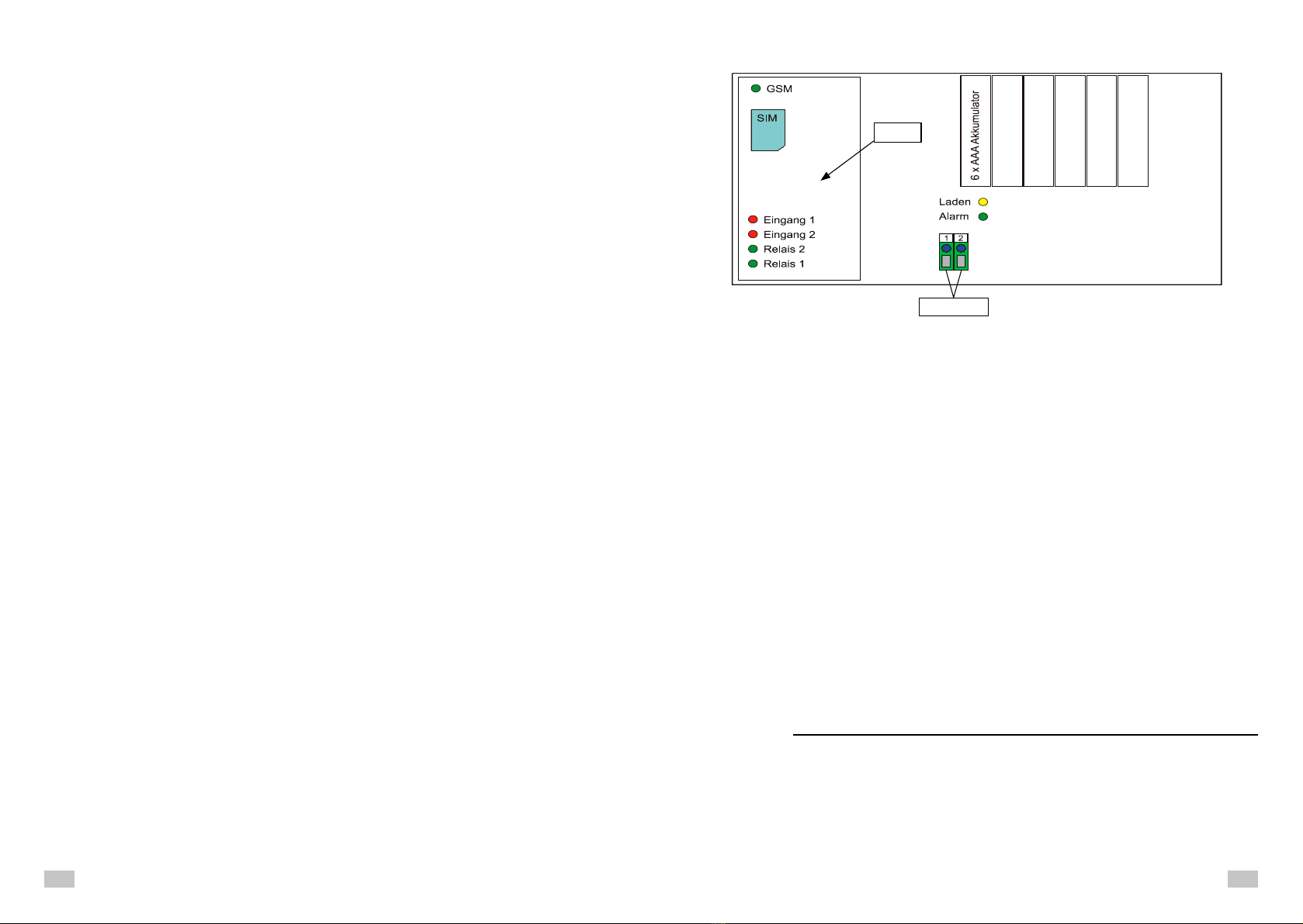
Connections and displays
Charging The charge display lights up when the batteries are being charged.
When the batteries are completely charged, the LED goes out.
Alarm The alarm-LED goes out when alarm input 1 is connected to the GND connection.
Relay 1 LED lights up when relay 1 has activated on the modem. If connected, the switchable so-
cket for the electric fence controller is in switched off condition.
Relay 2 The LED lights up when relay 2 has activated on the modem.
Input 1 The LED lights up when alarm input 1 is connected to the GND connection.
In the standard configuration, this means that there is no alarm.
Input 2 The LED lights up when alarm input 2 is connected to the GND connection.
GSM LED Permanently illuminated: A search is made of the mobile telephone network
Regularly flashes briefly: The connection exists to the mobile telephone network.
Flashes: SMS commands received are processed or sent.
Both LED "input 1" and "input 2" are also briefly switched on while the modem looks for the mobile
telephone network. They flash alternately when the modem is waiting for the configuration call.
The contacts of relay 2 on the modem card are directly connected with the terminals 1 and 2. An addi-
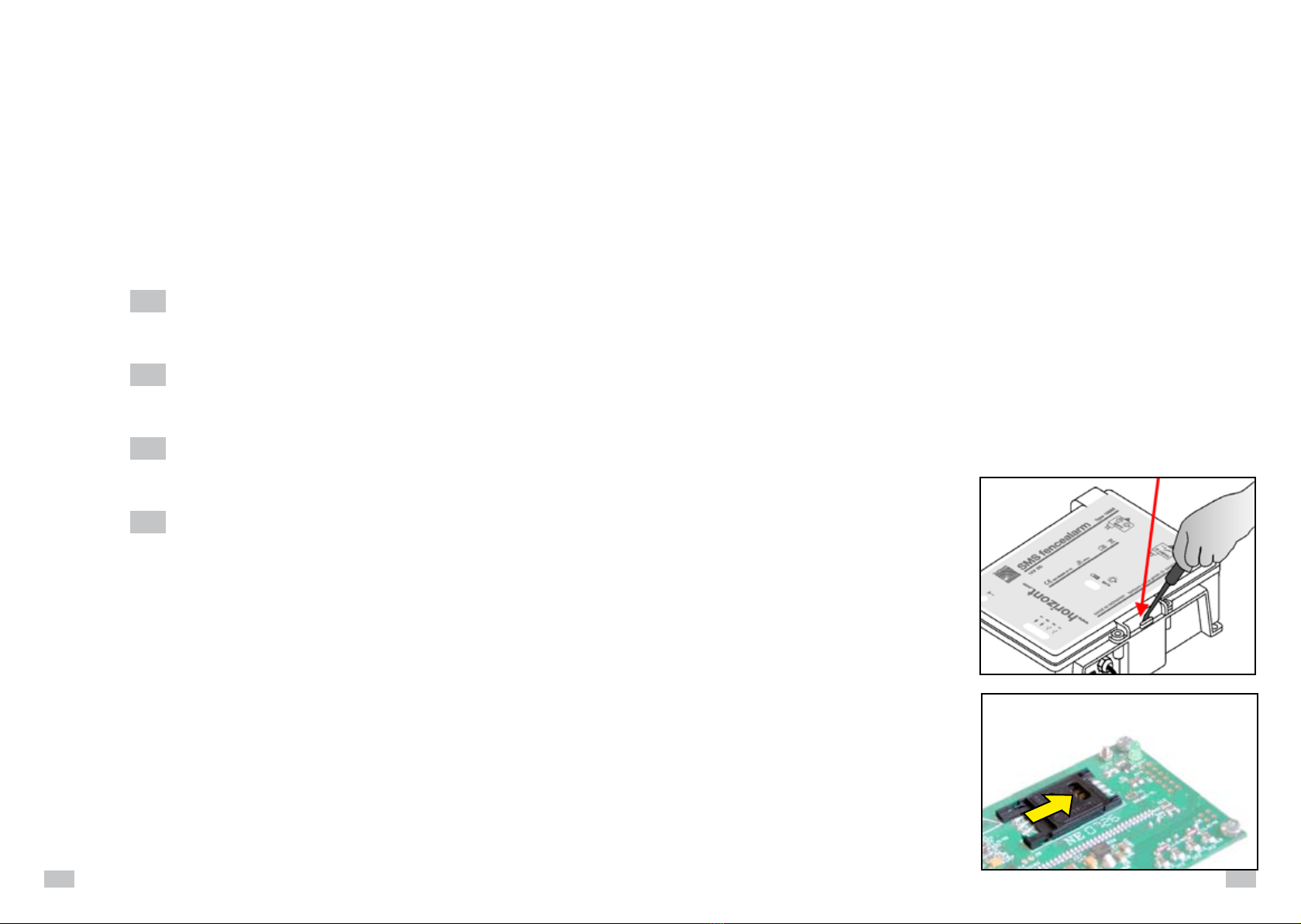
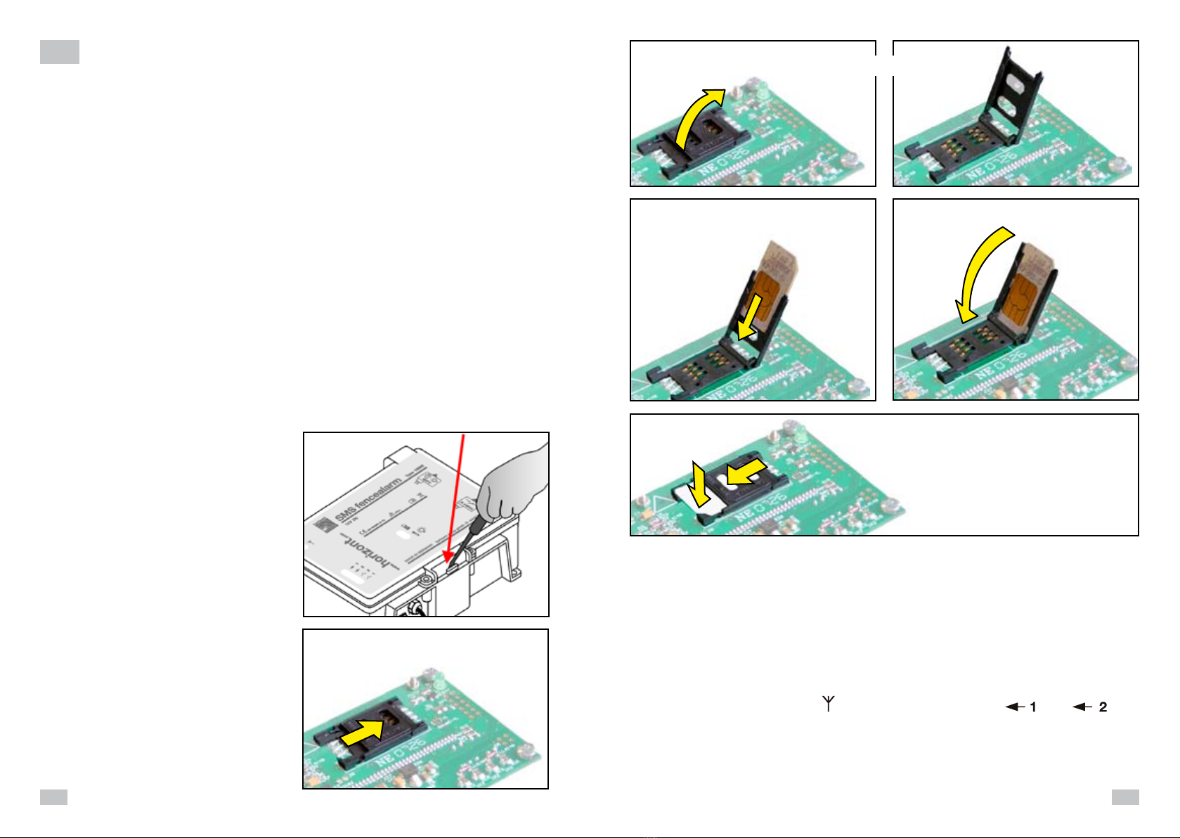
tional device (max. 42V/6A) can be connected there. Relay 2 can be switched via SMS commands. 2.) Dégagez le logement de la carte SIM en
poussant le verrou dans le sens affiché.
1. Mettez la carte SIM qui est destinée au "SMS
fencealarm" dans votre téléphone portable
et mettez le PIN sur "0000". Réglez en plus
la carte SIM de telle sorte que le numéro
d’appel soit transmis à l’appelé. Testez le PIN,
la transmission du numéro d’appel et l’envoi
et la réception de messages SMS avec votre
téléphone portable avant d’insérer la carte SIM
dans le "SMS fencealarm". Adressez-vous en
cas de problèmes à votre commerçant qui
vous a vendu la carte SIM.
2. Mettez le "SMS fencealarm" hors circuit. Le
bloc d’alimentation ne doit pas être branché.
3. Ouvrez l’appareil.
La carte SIM ne doit
être mise et/ou remplacée que lorsque
l’alimentation en courant est coupée (bloc
d’alimentation et accumulateurs). Aucune
DEL ne doit être allumée. Tout changement
sous tension d’alimentation peut conduire à
l’endommagement durable de la carte SIM
ou du modem.
Mettez la carte SIM, (voir figures 1 - 6 !).
1.) Ouvrez
Lappareil
Chère cliente, cher client,
Nous vous félicitons de l’achat de notre appareil de contrôle „SMS fencealarm“ et vous
remercions de votre confiance.
La surveillance mobile de vos pâtures par un radiotéléphone est indispensable en particulier pour les
clôtures longues et éloignées. C’est pour cela que nous avons mis au point l’appareil de contrôle „SMS
fencealarm“ qui peut être utilisé pour la surveillance et la commande de clôtures électriques pour ani-
maux. Vous n’avez besoin que d’une carte de téléphonie mobile de votre choix et chaque alarme peut
être transmise, de la clôture, à un radiotéléphone.
L’appareil de contrôle „SMS fencealarm“ peut être utilisé au choix via le bloc d’alimentation fourni
sur la tension de réseau 230 volts ou une batterie humide 12 volts. En cas de panne de la tension de
réseau, l’envoi d’un message d’erreur est assuré par les accumulateurs intégrés.
L’appareil de contrôle „SMS fencealarm“ peut être directement branché sur les électrificateurs de
clôture „horiSMART A50 Alarm“ (art. n° 10657) et „horiSMART N70 Alarm“ (art. n° 10656). Les clôtures
qui sont équipées avec d’autres électrificateurs peuvent également être surveillées en liaison avec le
contrôleur de clôture „fencecontrol“ (art n° 10535 = 230 volts; art n° 10545 = 12 volts). Si la tension de
la clôture tombe sous la valeur de protection de 2000 volts, l’appareil de contrôle est activé et émet un
SMS correspondant à un ou plusieurs portables. Les messages et numéros de téléphone peuvent être
réglés individuellement.
En option, il est possible de brancher sur l’appareil de contrôle „SMS fencealarm“ jusqu’à deux prises
de courant avec interrupteur (art. n° 10667). Une telle prise de courant permet de mettre en et hors
circuit l’électrificateur par un simple appel du téléphone portable. Il est possible également de brancher
d’autres appareils d’alarme (par ex. des lampes éclair, art. n° 14190 ou des sirènes, art. n° 14191).
En cas de panne de la tension de réseau sur l’électrificateur, un SMS correspondant est également
envoyé à un ou plusieurs portables. Le fonctionnement de l’appareil de contrôle „SMS fencealarm“ est
assuré, dans ce cas, par les accumulateurs intégrés.
Nous aimerions vous expliquer ci-dessous, étape par étape, la commande et le mode de fonctionne-
ment de votre appareil de contrôle:
Mise en service du détecteur d’alarme
Pour rendre opérationnel l’appareil, procédez
comme suit:
Additional note:
Please note that the “SMS fencealarm“ must not be used as a replacement for an alarm system!
The hardware and software is not fault tolerant, i.e. perfect functioning cannot always be assumed
under all conditions. Therefore, you must never rely exclusively on the “SMS fencealarm“.
Faults must be reckoned with, both with the “SMS fencealarm“, and with the voltage supply and the
GSM network connection. The transmission of SMS messages is normally fast and problem-free but
there is no 100% guarantee. Although this happens very rarely, SMS messages can be transmitted with
a very long transmission time or not at all.
Relay 2 (1, 2)
Modem
Input 1
Input 2
Relay 2
Relay 1
Charging
Alarm

18
19
8. Le modem est maintenant réglé sur le numéro d’appel du téléphone portable utilisé. Ce réglage
reste maintenu même après la mise hors circuit du "SMS fencealarm".
Pour tester, vous pouvez appeler le "SMS fencealarm". Le relais 1doit être actionné brièvement à
chaque appel (DEL verte clignote une fois).
9. Pour rendre opérationnel le téléavertisseur, il faut maintenant envoyer, selon le mode, le SMS de
configuration correspondant (voir page 5) de ce téléphone portable au "SMS fencealarm": pour
confirmation, un SMS est renvoyé avec les réglages actuels. On peut ajouter à tout moment
d’autres numéros avec autorisation de commutation et configuration et, dans des cas particuliers,
convenir d’autres réglages et textes (voir commandes SMS).
10. Si nécessaire, insérez maintenant
les accus (ne pas utiliser de bat-
teries normales !!!) et enlevez la
plaquette d’isolation.
La DEL de chargement ( ) s’allume.
Elle s’éteint lorsque les accus sont
chargés (après env. 2 h).
3.) Tournez le logement dans une position verticale.
4.) Poussez la carte avec précaution dans le loge-
ment. Veillez ici à la position (coin biseauté en
haut, contact doré vers le bas – voir fig.)
5.) Rabattez de nouveau le logement de la carte.
6.) Fermez le logement en poussant avec précaution
le verrou vers le bas jusqu’à ce qu’un clic audible
se fasse entendre. Assurez-vous que le logement
soit bien encliqueté.
4. Lisez le CODE à quatre caractères pour les commandes SMS qui se trouve sur l’autocollant du
circuit imprimé. Le CODE peut être modifié ultérieurement, à tout moment, par des commandes
SMS correspondantes.
ATTENTION – en cas de perte du code, il faut envoyer l’appareil !
5. Préparez le téléphone portable sur lequel les messages d’alarmes doivent être reçus et qui doit être
utilisé pour la télécommande. Le téléphone portable doit également être réglé de telle sorte que le
numéro d’appel soit transmis à l’appelé. Le mieux est d’entrer déjà le numéro d’appel du modem
(carte SIM) dans le téléphone portable.
6. Branchez le bloc d’alimentation ou l’accumulateur et allumez l’appareil (= actionner le commu-
tateur à bascule sur la partie inférieure du boîtier de l’appareil). La DEL d’alarme verte affiche
qu’aucune alarme n’a été déclenchée.
7. Dès que la diode GSM verte ( ) clignote et les deux diodes rouges ( ) et ( ) clignotent
alternativement, cela doit être le cas après env. 1 min., appelez le détecteur d’alarme avec votre
téléphone portable. Le détecteur d’alarme se règle sur le portable. Pour confirmation, 4 tons sont
renvoyés et peuvent être entendus dans le téléphone portable.
Si le modem n’a pas encore reçu d’appel après 3 min., il s’éteint automatiquement. Pour attendre
de nouveau l’appel de configuration, le détecteur d’alarme doit être éteint et de nouveau allumé.
Contact d'alarme NC
Lampe / sirène d'alarme
Electrificateur
Branchements
Bloc
d'alimentation
ou 12V DC
prise de
courant
avec
interrupteur
prise de
courant
avec
interrupteur
Réglages: Les prises de courant avec inter-
rupteur (ou commutateurs d’accu) ne doivent
être branchées qu’en cas de besoin. La confi-
guration maximale est représentée dans la figure
ci-dessus. L’alimentation en courant du "SMS
fencealarm" a lieu via le bloc d’alimentation four-
ni ou un accu supplémentaire (12V DC).
ATTENTION !!! Ne branchez ou débrancher
les prises de courant avec interrupteur que si
l’électrificateur branché est hors circuit. Cela
peut conduire, sinon, à l’endommagement du
"SMS fencealarm".

20
21
SMS de configuration:
Envoyez un SMS avec les caractères suivants à l’appareil d’alarme. Le
CODE
à quatre caractères se
trouve sur le circuit imprimé dans l’appareil d’alarme.
Veuillez prêter attention à la différence entre le chiffre "0" et la lettre "O".
On n’utilise généralement que des lettres majuscules.
CODE
O1:0.I1:2.I2:4.V1:0.V2:1.S:1.PT:CONTROLEUR MARCHE.E1:ALARME CLOTURE.E2:230V.
Les différentes commandes signifient:
O1:0. Sortie 1 commute durablement
(prise de courant avec interrupteur pour l’électrificateur active)
I1:2. Temps de rebondissement entrée 1 = 2s
I2:4. Temps de rebondissement entrée 2 = 4s
V1:0. Alarme si l’entrée 1 est activée
V2:1. Alarme si l’entrée 2 n’est pas activée
S:1. SMS de mise en circuit est envoyé
PT:CONTROLEUR MARCHE. Texte pour le SMS de mise en circuit
E1:ALARME CLOTURE. Texte pour le SMS d’alarme
E2:230V. Texte pour le SMS en cas de panne de tension de service
En cas d’utilisation de ces réglages, tous les messages sont envoyés au téléphone portable avec le-
quel l’appel de configuration a été effectué:
- En cas de réception correcte du réseau de téléphonie mobile, la DEL GSM verte ( ) clignote
régulièrement (après env. 1min).
- Après chaque mise en circuit, un SMS est envoyé avec le texte "CONTROLEUR MARCHE ".
- Lorsque le contact d’alarme est ouvert (pas d’alarme déclenché), la DEL rouge ( ) (entrée 1)
ne s’allume pas. Lorsque la tension réseau existe, la DEL rouge ( ) (entrée 2) s’allume.
- Si le contact d’alarme est fermé, la DEL ( ) s’allume et la DEL d’alarme ( ) verte s’éteint.
Un SMS avec le texte "ALARME CLOTURE" est envoyé.
- Une prise de courant avec interrupteur sur la douille d’alarme est normalement hors circuit.
En cas d’alarme de clôture, elle est mise en circuit et les appareils d’alarme branché est activé.
- Si l’on utilise des accus, ceux-ci sont chargés. La DEL jaune ( ) s’allume pendant le chargement.
La DEL s’éteint lorsque les accus sont chargés.
- La DEL ( ) s’éteint en cas de panne de 230V (ou de la tension de service 12V).
Un SMS avec le texte „230V“ est envoyé lorsque les accus de soutien sont chargés.
- Une prise de courant avec interrupteur sur la douille de commutation est également mise en circuit
après la mise en circuit. La DEL ( ) verte ne s’allume pas. Un appel du téléphone portable
utilisé pour la configuration met hors circuit la prise de courant, la DEL ( ) s’allume. Un nouvel
appel la met de nouveau en circuit, etc. Si l’électrificateur est exploité via cette prise de courant,
l’appareil peut être mis en et hors circuit via le téléphone portable en cas de travaux de mainte-
nance.
Les commandes SMS suivantes activent également les prises de courant:
CODE
O1ON. met hors circuit la prise de courant
CODE
O1OFF. met en circuit la prise de courant
- Pour le contrôle de fonctionnement, on peut envoyer un SMS avec le contenu:
CODE
ST? au "SMS fencealarm".
L’appareil renvoie alors un SMS avec les réglages actuels.
Fonctions supplémentaires
- Le SMS
CODE
O2ON.
relie les contacts 1 et 2 (max. 42V/6A) sur la barrette de connexion interne (DEL s’allume ).
- Le SMS
CODE
O2OFF.
coupe les contacts 1 et 2 sur la barrette de connexion (DEL arrêt).
Accus de soutien internes
Si l’appareil n’est pas utilisé pendant une période prolongée, veuillez retirer les accumulateurs ou
glissez la plaquette d’isolation entre un accu et le contact du consommateur.
Prise de courant avec interrupteur
Les prises de courant avec interrupteur sont disponibles en option (art. n° 10667) et offrent la possi-
bilité de brancher d’autres appareils d’alarme (par ex. sirène, art. n° 14191 ou lampe clignotante, art.
n° 14190) ou de mettre en et hors circuit l’électrificateur avec le téléphone portable. La tension de
commutation max. s’élève à 250VAC pour 10A.
Commandes SMS
Le cœur du "SMS fencealarm" est un module télémétrique avec deux entrées et deux sorties relais.
L’entrée 1 est utilisée comme entrée d’alarme ( DEL correspondante s’allume ) lorsque le contact
d’alarme est fermé, c’est-à-dire qu’il y a un défaut.
Entrée 2 est active ( DEL correspondante s’allume) lorsqu’une source de tension externe (bloc
d’alimentation ou accu ) est enfichée.
Sortie 1 active la prise de courant avec interrupteur branchée sur la douille de commutation, prise de
courant à l’aide de laquelle par ex. l’électrificateur peut être mis en et hors circuit. Après la mise en
circuit le contact relais est ouvert et ainsi la prise de courant avec interrupteur est en circuit.
La sortie 2 est librement disponible sur les bornes internes 1 et 2. On ne peut commuter que des tensi-
ons allant jusqu’à max. 40V et des courants allant jusqu’à max. 6A. Après la mise en circuit, le contact
relais est ouvert.
D’autres réglages peuvent avoir lieu à l’aide de différentes commandes SMS.
Chaque SMS doit commencer par un code à 4 caractères afin de protéger le "SMS fencealarm" contre
tout accès non autorisé. Vous trouverez le code réglé en usine sur l’autocollant placé sur le circuit im-
primé dans le "SMS fencealarm". Vous pouvez également changer le code. En cas de perte du code,
veuillez prendre contact avec notre usine à Korbach.
Toutes les commandes, sauf "R:" et "ST?" doivent être conclues par un point.
On peut envoyer simultanément, dans un SMS, plusieurs commandes séparées par ce point.
Les indications en secondes peuvent être de 1 à 5 chiffres sans un zéro au début, par ex. 1 ou 90 ou
67599 mais pas 0123.
Veuillez prêter attention à la différence entre le chiffre "0" et la lettre "O".
On n’utilise généralement que des lettres majuscules.

22
23
Tous les réglages restent maintenus même après la coupure de la tension d’alimentation.
O1:
XXXX
., O2:
XXXX
.(
XXXX
= secondes)
Les temps de commutation pour les relais sont réglés sur
XXXX
.
Chaque appel du téléphone utilisé pour l’appel de configuration (ou d’un téléphone dont le numéro
est enregistré dans la liste CLIP) met en circuit le relais 1 pour le temps indiqué.
Si l’on utilise pour
XXXX
la valeur "0", chaque appel commute durablement le relais.
Dans ce cas, un SMS met en circuit le relais 1 avec "O1ON." (prise de courant avec interrupteur arrêt)
et un SMS met hors circuit le relais 1 avec "O1OFF." (prise de courant avec interrupteur marche).
Le relais 2 se comporte en conséquence ("O2ON.", "O2OFF.").
O1:
XXXX
., I2:
XXXX
.
(XXXX
= secondes)
On règle sur les deux entrées le temps pendant lequel l’entrée doit être active avant qu’un message
soit envoyé (rebondissement).
V1:
X
., V2:
X
. (
X
=1 ou 0)
Pour x=0, on envoie un SMS d’alarme au cas où l’entrée correspondante était active plus longue
que le temps réglé et inavtive pour x=1.
S:
X
.(
X
=1 ou 0)
Pour
X
=1 on envoie un SMS dès que le module est en circuit.
Pour
X
=0 on n’envoie aucun message "de mise en circuit".
R:
Le module est remis dans l’état de livraison.
ST?
Le module renvoie les réglages actuels sous forme de SMS. Ce SMS peut être utilisé pour tester
la liaison et vous pouvez voir si les sorties sont en ou hors circuit.
PN:
CODE à 4 caractères.
Le code est modifié. Le code peut se composer de n’importe quelles lettres (que des majuscules)
et chiffres. Les caractères spéciaux ne sont pas permis.
C2:
NUMERO DE TELEPHONE.,
C3:
NUMERO DE TELEPHONE.,
C4:
NUMERO DE TELEPHONE.,
C5:
NUMERO DE TELEPHONE.
La commande convient jusqu’à 4 autres numéros d’alarme auxquels les messages "de mise en
circuit" et "d’alarme" sont envoyés. Ces numéros d’appel peuvent également commuter le relais 1
en appelant mais ne peuvent pas exécuter de configuration ou autre action par SMS.
CL:
NUMERO DE TELEPHONE.
La commande CL mémorise jusqu’à cent autres numéros d’appel qui commutent le relais 1 en
cas d’appel.
CD:
NUMERO DE TELEPHONE.
CD efface les numéros correspondants de la liste.
E1:
TEXTE.
Mémorise le texte qui est envoyé en cas d’alarme à l’entrée 1 (électrificateur).
E2:
TEXTE.
Mémorise le texte qui est envoyé en cas d’alarme à l’entrée 2 (alimentation en courant externe).
PT:
TEXTE.
Mémorise le texte qui est envoyé en cas de mise en circuit du "SMS fencealarm".
Chargement L’affichage de charge s’allume lorsque les accumulateurs sont chargés.
La DEL s’éteint lorsque les accumulateurs sont entièrement chargés.
Alarme La DEL d’alarme s’éteint lorsque l’entrée d’alarme 1 est reliée à la connexion GND.
Relais 1 La DEL s’allume lorsque le relais sur le modem est actionné. Si elle est connectée,
la prise de courant avec interrupteur pour l’électrificateur est coupée.
Relais 2 La DEL s’allume lorsque le relais 2 sur le modem est actionné.
Entrée 1 La DEL s’allume lorsque l’entrée d’alarme 1 est reliée à la connexion GND.
Dans la configuration standard, cela signifie qu’il n’y a pas d’alarme.
Entrée 2 La DEL s’allume lorsque l’entrée d’alarme 2 est reliée à la connexion GND.
DEL GSM Allumée durablement: Le réseau de téléphonie mobile est recherché
Jette régulièrement un éclair: La liaison avec la réseau de téléphonie mobile est établie.
Clignote: Des commandes SMS sont traitées ou reçues.
Les deux DEL "entrée1" et "entrée 2" sont également brièvement allumées pendant que le modem
recherche le réseau de téléphonie mobile. Elles clignotent à contretemps lorsque le modem attend
l’appel de configuration.
Les contacts du relais 2 sur la carte du modem sont reliés directement avec les bornes 1 et 2. On
peut allumer là un appareil supplémentaire (max. 42V/6A). Le relais 2 peut être commuté via des com-
mandes SMS.
Indication supplémentaire:
Veuillez observer que le „SMS fencealarm“ ne peut pas être utilisé pour remplacer une installation
d’alarme! Le matériel et le logiciel ne sont pas tolérants à l’erreur, ce qui signifie qu’il n’est pas toujours
possible de compter sur un parfait fonctionnement et dans toutes les conditions. Vous ne pouvez pas
compter exclusivement sur le „SMS fencealarm“. Il faut compter sur le mauvais fonctionnement aussi
bien du „SMS fencealarm“ que concernant l’alimentation en tension et la liaison au réseau GSM. La
transmission des messages SMS a certes lieu d’une manière généralement parfaite et rapide mais
sans garantie à 100%. Même si cela arrive extrêmement rarement, il est possible que des messages
SMS ne soient transmis qu’après une très longue période voire pas du tout.
Branchements et affichages
Relais 2 (1, 2)
Modem
Entrée 1
Entrée 2
Relais 2
Relais 1
Chargement
Alarme

24
25
nl 3.) Draai de houder in een loodrechte positie.
4.) Schuif de kaart voorzichtig in de houder.
Let daarbij op de ligging (afgeschuinde
hoek bovenaan en goudcontact naar be-
neden – zie afbeelding)
5.) Klap de kaarthouder weer in.
6.) Sluit de houder doordat u het blokkeerschuifje voor-
zichtig naar beneden schuift tot er een klik te horen is.
Zorg er beslist voor dat de houder vast geklikt is.
2.) Maak de SIM-kaarthouder los doordat u het
blokkeerschuifje in de aangegeven richting
verschuift.
1.) Open het
apparaat
Geachte cliënte, Geachte klant,
Wij feliciteren u met de aankoop van ons controleapparaat „SMS fencealarm“ en danken u voor
uw vertrouwen.
Vooral voor lange en afgelegen afrasteringinstallaties is de mobiele observatie van de bewakingsveiligheid
door middel van een radiotelefoon absoluut noodzakelijk. Hiervoor hebben wij het controleapparaat „SMS-
fencealarm“ ontwikkeld, dat voor de bewaking en de sturing van elektrische afrasteringen voor dieren
gebruikt kan worden. U hebt enkel een radiotelefoonkaart naar uw keuze nodig en ieder alarmsignaal kan
van de afrasteringinstallatie naar een radiotelefoon overgebracht worden.
Het controleapparaat „SMS-fencealarm“ kan facultatief via de bijgeleverde stekkervoedingseenheid door
middel van 230 volt netspanning of een natte batterij van 12 volt gebruikt worden. Bij uitval van de netspan-
ning wordt het zenden van de foutmelding door de ingebouwde accumulatoren gegarandeerd.
Het controleapparaat „SMS-fencealarm“ kan rechtstreeks op de weideafrasteringapparaten „horiSMART
A50 alarm“ (art.-nr. 10657) en „horiSMART N70 alarm“ (art.-nr. 10656) aangesloten worden. De afraste-
ringinstallaties, die met andere weideafrasteringapparaten gebruikt worden, kunnen in verbinding met de
afrasteringbewakende eenheid „fencecontrol“ (art.-nr. 10535 = 230 volt; art.-nr. 10545 = 12 volt) eveneens
bewaakt worden. Indien de spanning van de afrastering tot onder de voor de bewaking veilige waarde van
2000 volt daalt, wordt het controleapparaat geactiveerd en zendt het een daarmee overeenstemmende
SMS naar één of meerdere mobiele telefoon(s). De meldingsteksten en telefoonnummers zijn individueel
instelbaar.
Optioneel kunnen er op het controleapparaat „SMS-fencealarm“ maximaal twee schakelbare contactdo-
zen aangesloten worden (art.-nr. 10667). Door middel van een dergelijke contactdoos kan door een een-
voudige telefonische oproep van de mobiele telefoon het weideafrasteringapparaat in- c.q. uitgeschakeld
worden of kunnen er nog andere alarmapparaten (bijvoorbeeld flitslicht, art.-nr. 14190 of sirene, art.-nr.
14191) aangesloten worden.
Bij een uitval van de netspanning aan het wiedeafrasteringapparaat wordt er eveneens daarmee ove-
reenstemmende SMS naar één of meerdere mobiele telefoons gezonden. De werking van het controleap-
paraat „SMS-fencealarm“ wordt in dit geval door de ingebouwde accumulatoren gewaarborgd.
Hierna zouden wij u stap voor stap de bediening en de werkwijze van uw controleapparaat willen uitleggen:
Inbedrijfstelling van de alarmmelder
Om het apparaat operationeel te maken, gaat u als
volgt te werk:
1. Leg de SIM-kaart, die voor het "SMS fencea-
larm" bestemd is, in uw mobiele telefoon en zet
de PIN op "0000". Stel bovendien de SIM-kaart
zodanig in, dat het telefoonnummer naar de op-
gebelde persoon overgebracht wordt. Test PIN,
overdracht van het telefoonnummer en de ver-
zending en ontvangst van SMS-berichten met
uw mobiele telefoon, voordat u de SIM-kaart in
het "SMS fencealarm" legt. Gelieve u in geval van
problemen te richten tot de handelaar, die u de
SIM-kaart verkocht heeft.
2. Schakel het "SMS fencealarm" uit. Er mag geen
voedingseenheid aangesloten zijn.
3. Open het apparaat.
De SIM-kaart mag uitslu-
itend bij een uitgeschakelde stroomvoorzi-
ening (voedingseenheid en accumulatoren)
aangebracht en/of gewisseld worden. Geen
enkele LED mag verlicht zijn. De wissel bij
beschikbare voedingsspanning kan tot een
blijvende beschadiging van de SIM-kaart of
van de modem leiden.
Leg de SIM-kaart in (zie afbeeldingen 1 - 6!).
4. Lees het uit vier cijfers bestaande SLEUTELWOORD voor de SMS-commando’s van het etiket op de
printplaat af. Het SLEUTELWOORD kan later door daarmee overeenstemmende SMS-commando’s te
allen tijde gewijzigd worden.
OPGELET – in geval van verlies van het wachtwoord moet het apparaat ingezonden worden!
5. Leg de mobiele telefoon gereed, waarop de alarmmeldingen ontvangen worden en die voor de afstands-
bediening gebruikt dient te worden. De mobiele telefoon moet eveneens zodanig ingesteld zijn, dat het
telefoonnummer naar de opgebelde persoon overgebracht wordt. Voer het best het telefoonnummer van
de modem (SIM-kaart) reeds in de mobiele telefoon in.
6. Sluit de voedingseenheid of de accumulator aan en schakel het apparaat in (= tuimelschakelaar aan het
onderste gedeelte van de behuizing van het apparaat indrukken). De groene alarm-LED geeft aan dat er
geen alarm geactiveerd is.
7. Zodra de groene GSM-diode ( ) knippert en de beide rode dioden ( ) en ( ) beurtelings
knipperen – dat zou na ca. 1 minuut het geval moeten zijn – belt u de alarmmelder met uw mobiele
telefoon op. De alarmmelder stelt zich op de mobiele telefoon in. Als bevestiging worden er 4 tonen
teruggezonden, die in de mobiele telefoon te horen zijn. Als de modem na 3 minuten nog geen telefo-
nische oproep gekregen heeft, schakelt hij zich automatisch uit. Om opnieuw op de configuratieoproep
te wachten, moet de alarmmelder uit- en terug ingeschakeld worden.

26
27
8. De modem is nu op het telefoonnummer van de gebruikte mobiele telefoon ingesteld. Deze instel-
ling blijft ook na het uitschakelen van het "SMS fencealarm" behouden.
Bij wijze van test kunt u het "SMS fencealarm" opbellen. Het relais 1dient bij iedere telefonische
oproep even te reageren (groene LED gaat knipperen).
9. Om het radiozendapparaat operationeel te maken, moet nu – al naargelang de modus – de cor-
responderende configuratie-SMS (zie pagina 5) vanuit deze mobiele telefoon naar het "SMS fen-
cealarm" gezonden worden: als bevestiging wordt er een SMS met de actuele instellingen terug-
gezonden. Er kunnen te allen tijde nog andere nummers met schakel- en configuratieautorisatie
toegevoegd c.q. kunnen er in speciale gevallen ook andere instellingen en teksten overeengekomen
worden (zie SMS-commando’s).
10. Zo nodig, legt u nu de accu’s (geen
normale batterijen gebruiken!!!) in
c.q. verwijdert u het isolatieplaatje.
De laad-LED ( ) flitst aan. Ze dooft
wanneer de accu’s geladen zijn (na
ca. 2 h).
Instellingen
De schakelbare contactdozen (c.q. accuscha-
kelaars) hoeven slechts zo nodig aangesloten
te worden. In de bovenstaande afbeelding is de
maximale configuratie weergegeven. De stroom-
voorziening van het "SMS fencealarm" gebeurt
door middel van de bijgeleverde voedingseen-
heid of een bijkomende accu (12V DC).
OPGELET!!! Sluit de schakelbare contactdo-
zen enkel in of uit wanneer het aangesloten
weideafrasteringapparaat uitgeschakeld is.
In het andere geval kan het tot de beschadi-
ging van het "SMS fencealarm" komen.
Alarmcontact NC
Alarmlamp /-sirene
Weideafrasteringapparaat
Aansluitingen
schakelbare
contactdoos
schakelbare
contactdoos
Stekker-
voedingseenheid
of 12V DC
Configuratie - SMS:
Zend een SMS met volgende karakters naar het alarmtoestel.
Het uit vier cijfers bestaande
SLEUTELWOORD
vindt u op de printplaat in het alarmtoestel.
Gelieve ook op het verschil tussen het cijfer "0" en de letter "O" te letten.
Over het algemeen worden er enkel drukletters gebruikt.
SLEUTELWOORD
O1:0.I1:2.I2:4.V1:0.V2:1.S:1.PT:VOLGSCHAKELAAR AAN.E1:AFRASTERINGALARM.E2:230V.
De individuele commando’s hebben volgende betekenis:
O1:0. Uitgang 1 schakelt duurzaam om
(schakelbare contactdoos voor het weideafrasteringapparaat schakelt)
I1:2. “Debouncing”-tijd ingang 1 = 2s
I2:4. “Debouncing”-tijd ingang 2 = 4s
V1:0. Alarm, wanneer ingang 1 geactiveerd is
V2:1. Alarm, wanneer ingang 2 niet geactiveerd is
S:1. Inschakel-SMS wordt gezonden
PT:VOLGSCHAKELAAR AAN. Tekst voor inschakel-SMS
E1:AFRASTERINGALARM. Tekst voor alarm-SMS
E2:230V. Tekst voor SMS bij uitval van de bedrijfsspanning
Bij gebruikmaking van deze instellingen worden alle boodschappen gezonden naar de mobiele telefoon,
waarmee de configuratieoproep doorgevoerd werd.
Volgende functies staan ter beschikking:
- Bij een behoorlijke ontvangst van het mobiele telefoonnetwerk knippert de groene GSM-LED ( )
gelijkmatig (na ca. 1 minuut).
- Telkens na het inschakelen wordt er een SMS met de tekst "VOLGSCHAKELAAR AAN" gezonden.
- Bij een open alarmcontact (geen alarm geactiveerd) is de rode LED ( ) (ingang 1) niet verlicht.
Bij beschikbare netspanning is de rode LED ( ) (ingang 2) verlicht.
- Als het alarmcontact gesloten wordt, is de LED ( ) verlicht en dooft het groene alarm LED ( )
Er wordt een SMS met de tekst "AFRASTERINGALARM" gezonden.
- Een schakelbare contactdoos aan de alarmbus is normaliter uitgeschakeld. Bij een afrasteringalarm
wordt ze ingeschakeld en worden de daarop aangesloten alarmtoestellen geactiveerd.
- Als er accu’s gebruikt worden, worden deze opgeladen.
Tijdens het laden is de gele LED ( ) verlicht. Als de accu’s geladen zijn, dooft de LED.
- Bij een uitval van de 230 V (of van de 12 V bedrijfsspanning ), dooft de LED ( ).
Bij geladen steunaccu’s wordt er een SMS met de tekst "230 V" gezonden.
- Een schakelbare contactdoos aan de schakelbus is na het inschakelen eveneens ingeschakeld. De
groene LED ( ) is niet verlicht. Een telefonische oproep van de voor de configuratie gebruikte
mobiele telefoon schakelt de contactdoos uit (LED is verlicht). Een nieuwe telefonische oproep
schakelt ze weer in enz. Indien het elektrische afrasteringapparaat door middel van deze contactdoos
bediend wordt, kan het apparaat bij onderhoudswerkzaamheden via de mobiele telefoon in- en uit-
geschakeld worden. De volgende SMS-commando’s schakelen de contactdozen eveneens:
SLEUTELWOORD
O1ON. Schakelt de contactdoos uit
SLEUTELWOORD
O1OFF. Schakelt de contactdoos in
- Ter controle van de werking kan er een SMS met de inhoud:
SLEUTELWOORD
ST? naar het "SMS fencealarm" gezonden worden.
Het apparaat zendt vervolgens een SMS met de actuele instellingen terug.

28
29
Bijkomende functies
- Het SMS
SLEUTELWOORD
O2ON.
verbindt de contacten 1 en 2 (max. 42V/6A) aan de internen aansluitstrook (LED is verlicht).
- De SMS
SLEUTELWOORD
O2OFF.
scheidt de contacten 1 en 2 aan de interne aansluitstrook (LED uit).
Interne steunaccu’s
Indien het apparaat langere tijd niet gebruikt wordt, gelieve dan de accumulatoren uit te nemen of het
isolatieplaatje tussen een accu en het afnemercontact te schuiven.
Schakelbare contactdoos
De schakelbare contactdozen zijn optioneel verkrijgbaar (artikelnummer 10667) en bieden de moge-
lijkheid, nog andere alarmtoestellen aan te sluiten (bijvoorbeeld sirene, art.-nr. 14191 of knipperlamp,
art.-nr. 14190) c.q. het weideafrasteringapparaat met de mobiele telefoon in en uit te schakelen. De
maximale schakelspanning bedraagt 250VAC bei 10A.
SMS commando’s
De kern van het "SMS fencealarm" is een telemetriemodule met twee ingangen en twee relaisuit-
gangen.
Ingang 1 wordt als alarmingang gebruikt (bijbehorende LED is verlicht) wanneer het alarmcontact
gesloten is, d.w.z. wanneer er van een fout sprake is.
Ingang 2 is actief (bijbehorende LED is verlicht) wanner er een externe spanningsbron (voeding-
seenheid of accu) aangesloten is.
Uitgang 1 schakelt de op de schakelbus aangesloten schakelbare contactdoos, met diens hulp bijvoor-
beeld het weideafrasteringapparaat respectievelijk in- en uitgeschakeld kan worden. Na het inscha-
kelen is het relaiscontact open en daardoor de schakelbare contactdoos ingeschakeld.
Uitgang 2 is aan de interne klemmen 1 en 2 vrij beschikbaar. Er mogen uitsluitend spanningen tot ma-
ximaal 40 V en stromen tot maximaal 6A geschakeld worden. Na het inschakelen is het relaiscontact
open.
Met behulp van verschillende SMS-commando’s kunnen er nog andere instellingen doorgevoerd wor-
den.
Om het "SMS fencealarm" tegen een onbevoegde toegang te beschermen, moet iedere SMS met een
uit 4 cijfers bestaand sleutelwoord beginnen. Het in de fabriek ingestelde sleutelwoord vindt u op het
etiket op de printplaat in het "SMS fencealarm". U kunt het sleutelwoord ook wijzigen. Gelieve in geval
van verlies met onze fabriek in Korbach overleg te plegen.
Alle commando’s, behalve "R:" en "ST?", moeten met een punt beëindigd worden.
Meerdere commando’s kunnen gescheiden door dit punt in één SMS gelijktijdig verzonden worden.
De weergave van de seconden kan 1-5 cijfers lang zijn zonder nullen vooraan, bijvoorbeeld 1 of 90 of
67599, maar niet 0123.
Gelieve ook op het verschil tussen het cijfer "0" en de letter "O" te letten.
Over het algemeen worden er enkel drukletters gebruikt.
Alle instellingen blijven ook behouden nadat de voedingsspanning verbroken werd.
O1:XXXX., O2:
XXXX
.(
XXXX
= seconden)
De schakeltijden voor de relais worden op
XXXX
seconden ingesteld.
Iedere telefonische oproep van de voor de configuratieoproep gebruikte telefoon (of van een tele-
foon, waarvan het nummer in de CLIP-lijst geregistreerd is) schakelt het relais 1 voor de aangege-
ven tijdspanne in.
Als voor
XXXX
de waarde "0" gebruikt wordt, schakelt iedere telefonische oproep het relais du-
urzaam om.
In dit geval schakelt een SMS met "O1ON." het relais 1 in (schakelbare contactdoos “Uit”) en een
SMS met "O1OFF." het relais 1 uit (schakelbare contactdoos “Aan”).
Het relais 2 gedraagt zich in overeenstemming daarmee ("O2ON.", "O2OFF.").
O1:
XXXX
., I2:
XXXX
.(
XXXX
= seconden)
Voor de beide ingangen wordt de tijdspanne ingesteld, tijdens dewelke de ingang actief moet zijn
voordat er een melding geannuleerd wordt (“Debouncing”).
V1:
X
., V2:
X
.(
X
=1 of 0)
Bij x=0 wordt er een alarm-SMS gezonden indien de corresponderende ingang langer dan de inge-
stelde tijdspanne actief en bij x=1 inactief was.
S:
X
. (
X
=1 of 0)
Bij
X
=1 wordt er een SMS gezonden zodra de module ingeschakeld wordt.
Bij
X
=0 wordt er geen "inschakel"-melding gezonden.
R:
De module wordt terug naar de toestand bij levering gebracht.
ST?
De module zendt de actuele instellingen als SMS terug. Deze SMS kan gebruikt worden om de
verbinding te testen en u kunt zien, of de uitgangen in- c.q. uitgeschakeld zijn.
PN:
uit 4 cijfers bestaand SLEUTELWOORD.
Het sleutelwoord wordt gewijzigd. Het sleutelwoord mag uit 4 willekeurige letters (enkel drukletters)
en cijfers bestaan. Speciale tekens zijn niet toegestaan.
C2:
TELEFOONNUMMER,
C3:
TELEFOONNUMMER.,
C4:
TELEFOONNUMMER.,
C5:
TELEFOONNUMMER.
Het commando zorgt ervoor dat er maximaal 4 bijkomende alarmnummers naar de "inschakel"- en
"alarm"-meldingen verzonden worden. Deze telefoonnummers mogen eveneens het relais 1 per te-
lefonische oproep schakelen, maar kunnen geen configuratie of andere actie per SMS uitvoeren.
CL:
TELEFOONNUMMER.
Het commando CL slaat maximaal honderd extra telefoonnummers op, die bij een telefonische
oproep het relais 1 schakelen.
CD:
TELEFOONNUMMER.
Het commando CD wist het daarmee overeenstemmende nummer uit de lijst.
E1:
TEKST.
Slaat de tekst op, die bij een alarm aan ingang 1 (weideafrasteringapparaat) gezonden wordt.
E2:
TEKST.
Slaat de tekst op, die bij een alarm aan ingang 2 (externe stroomvoorziening) gezonden wordt.
PT:
TEKST.
Slaat de tekst op, die bij het inschakelen van het "SMS fencealarm" gezonden wordt.

30
31
Bijkomende opmerking:
Gelieve in acht te nemen dat het „SMS fencealarm“ niet als vervangmiddel voor een alarminstallatie
gebruikt mag worden! De hard- en software zijn niet tolerant voor fouten, wat betekent dat de foutloze
werking niet altijd en in alle omstandigheden vooropgesteld kan worden. U mag nooit uitsluitend op
het „SMS fencealarm“ alleen vertrouwen. Met foutieve functies moet er zowel bij het „SMS fencea-
larm“, als bij de spanningsvoorziening en de GSM-netwerkverbinding rekening gehouden worden. De
overdracht van SMS-berichten gebeurt weliswaar in principe foutloos en snel, maar niet met een 100%
sluitende garantie. Ook al gebeurt dit uiterst zelden, kunnen SMS-berichten pas met een zeer lange
inschakelduur of al helemaal niet overgedragen worden.
Aansluitingen en displays
Technical data
GSM dual band, EGSM 900/1800 MHz,
compatible with ETSI GSM phase 2+ standard
Output capacity: Class 4 (2W @ 900MHz)
Class 1 (1W @ 1800MHz)
Temperature range: -20°C ... +85°C
Operating voltage: 10V ... 15V DC
Technische Daten
GSM Dualband, EGSM 900/1800 MHz,
Kompatibel mit ETSI GSM Phase 2+ Standard
Ausgangsleistung: Class 4 (2W @ 900MHz)
Class 1 (1W @ 1800MHz)
Temperaturbereich: -20°C ... +85°C
Betriebsspannung: 10V ... 15V DC
Stromaufnahme:
in Ruhe 20 mA
Akku laden 300 mA
kurzeitig bis 800 mA
Relais 2: max. 42V/6A
Schaltbare Steckdose:
Steuerspannung 13V DC
Schaltspannung 250V AC
Schaltstrom 10A AC
Caractéristiques techniques
GSM double bande, EGSM 900/1800 MHz,
compatible avec ETSI GSM Phase 2+ Standard
Puissance de sortie: Class 4 (2W @ 900MHz)
Class 1 (1W @ 1800MHz)
Plage de température:
-20°C ... +85°C
Tension de service: 10V ... 15V DC
Laden Het laaddisplay is verlicht wanneer de accumulatoren geladen worden.
Als de accumulatoren volledig geladen zijn, dooft de LED.
Alarm De alarm-LED dooft wanneer de alarmingang 1 met de aansluiting GND verbonden is.
Relais 1
De LED flitst aan wanneer het relais 1 op de modem gereageerd heeft. Indien aangesloten,
is de schakelbare contactdoos voor het weideafrasteringapparaat uitgeschakeld.
Relais 2 De LED flitst aan wanneer het relais 2 op de modem gereageerd heeft.
Ingang 1 De LED flitst aan wanneer de alarmingang 1 met de GND-aansluiting verbonden is.
In de standaardconfiguratie betekent dit, dat er geen alarm is.
Ingang 2 De LED flitst aan wanneer de alarmingang 2 met de GND-aansluiting verbonden is.
GSM LED Is permanent verlicht: Het mobilofoonnetwerk wordt gezocht
Flitst regelmatig even aan:
De verbinding met het mobilofoonnetwerk is tot stand gebracht.
Knippert:
Er worden ontvangen SMS-commando’s verwerkt of verzonden.
De beide LED’s "Ingang 1" en "Ingang 2" worden ook even ingeschakeld terwijl de modem het mobilo-
foonnetwerk zoekt. Ze knipperen in balans wanneer de modem op de configuratieoproep wacht.
De contacten van het relais 2 op de modemkaart zijn rechtstreeks met de klemmen 1 en 2 verbonden.
Daar kan een bijkomend apparaat (max. 42V/6A) ingeschakeld worden. Relais 2 kan door middel van
SMS-commando’s geschakeld worden.
Technische gegevens
GSM Dualband, EGSM 900/1800 MHz,
compatibel met ETSI GSM fase 2+ standaard
Uitgangsvermogen: Class 4 (2W @ 900MHz)
Class 1 (1W @ 1800MHz)
Temperatuurbereik: -20°C ... +85°C
Bedrijfsspanning: 10V ... 15V DC
Charging rate:
Resting 20 mA
Charging battery 300 mA
Briefly up to 800 mA
Relay 2: max. 42V/6A
Switchable socket:
Control voltage 13V DC
Switching voltage 250V AC
Switching current 10A AC
Puissance absorbée:
au repos 20 mA
charger accu 300 mA
brièvement jusqu’à 800 mA
Relais 2: max. 42V/6A
Prise de courant avec interrupteur:
Tension de commande 13V DC
Tension de commutation 250V AC
Courant de commutation 10A AC
Stroomopname:
In rust 20 mA
Accu laden 300 mA
Kortstondig tot 800 mA
Relais 2: max. 42V/6A
Schakelbare contactdoos:
Stuurspanning 13V DC
Schakelspanning 250V AC
Schakelstroom 10A AC
fr
nl
en
de
Relais 2 (1, 2)
Modem
Ingang 1
Ingang 2
Relais 2
Relais 1

32
LEBEN MIT DEM TIER
horizont group gmbh
Division agrartechnik
Postfach 13 29
34483 Korbach
Homberger Weg 4-6
34497 Korbach
GERMANY
Telefon: +49 (0) 56 31 / 5 65-1 00
Telefax: +49 (0) 56 31 / 5 65-1 20
www.horizont.com
Table of contents
Languages: