1
1. Safety Instructions and Storage/ Battery Care
SAVE THESE INSTRUCTIONS. - This manual contains important instructions that should be followed during installation and
maintenance of the UPS and batteries.
Read the instructions carefully to become familiar with the equipment before starting the instillation process.
Notify the carrier and dealer if there is any damage to the unit. Do not install if unit has signs of physical damage.
Adhere to all national and local electrical codes.
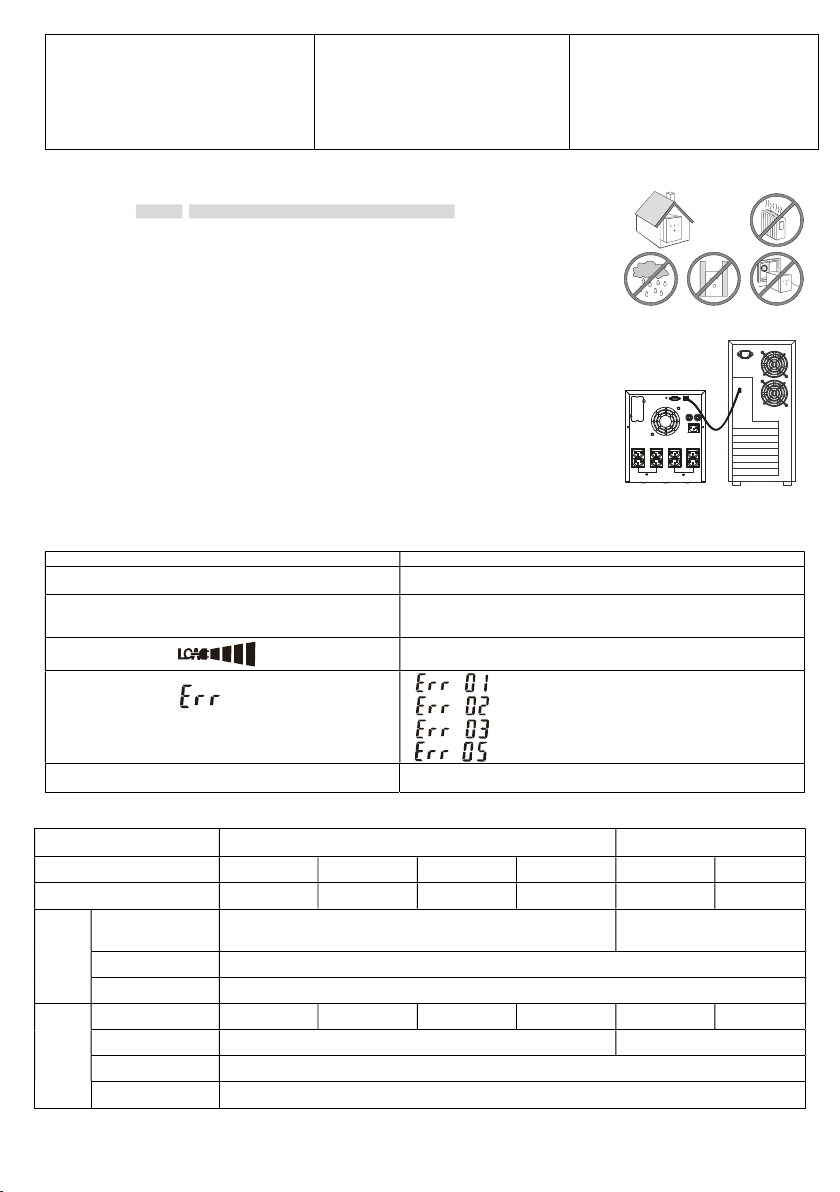
This UPS is intended for indoor use only.
Do not operate this UPS in direct sunlight, in contact with liquids, or where there is excessive dust or humidity.
Be sure the air vents on the UPS are not blocked. Allow adequate space for proper ventilation. Keep rear panel a minimum of 8 inches
(20cm) from any obstructions.
For a UPS with a factory installed power cord, connect the UPS power cable directly to a wall outlet. Do not use surge protectors or
extension cords. Use only the power cord supplied with the UPS.
The battery typically lasts for three to five years. Environmental factors will impact battery life. Elevated ambient temperatures, poor quality
utility power, and frequent short duration discharges will shorten battery life.
The equipment and batteries are heavy. Remove the batteries before lifting the UPS and practice safe lifting techniques adequate for the
weight of the equipment.
Before installing or servicing the equipment check that the Disconnecting from the AC mains and load. The UPS contains internal batteries
and may present a shock hazard even when disconnected from the branch circuit (mains).
Doing wiring, maintenance service and batteries replacement should be performed or supervised by personnel knowledgeable about
batteries and the required precautions.
When replacing batteries, replace with the same type and number of batteries or battery packs.
This UPS is intended for patient vicinity use only. Do not use this UPS for any life support applications or critical support.
CAUTION: Do not dispose of batteries into fire. The batteries may explode.
CAUTION: Do not open or mutilate batteries. Released electrolyte is harmful to the skin, eyes, and may be toxic.
CAUTION: A battery can present a risk of electrical shock and high short-circuit current through conductive materials and could cause
severe burns. The following precautions should be observed when working on batteries:
Before installing or replacing the batteries, remove jewelry such as wristwatches and rings, or other metal objects.
When working on batteries should wear rubber gloves and boots. Also, must use tools with insulated handles. Do not lay tools or metal
parts on top of batteries.
Remove battery grounds during installation and maintenance to reduce likelihood of shock. Remove the connection from ground if any
part of the battery is determined to be grounded.
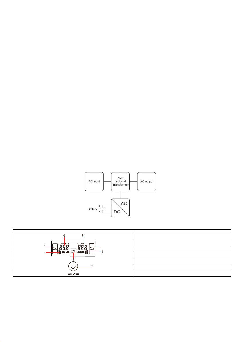
2. UPS System Block Diagram
3. Front Panel Display
1. AC mains mode
2. Battery/inverter mode
3. Automatic Voltage Regulation (Buck or Boost)
4. Battery capacity
5. Load capacity
6. UPS status
7. Power ON/OFF button