Nyfors AUTOCLEAVER LDF User manual

USER MANUAL

2
This manual is valid for AUTOCLEAVER LDF
with firmware version 2.13 and
AUTOCLEAVER Controller version 2.13

3
Introduction.......................................................................................................................................................................... 6
General information ......................................................................................................................................................... 6
At a glance ........................................................................................................................................................................ 6
Safety information................................................................................................................................................................ 7
Safety warnings and precautions...................................................................................................................................... 7
Operational safety warnings............................................................................................................................................. 7
Transport and storage precautions .................................................................................................................................. 8
External care precautions ................................................................................................................................................. 8
Upon delivery........................................................................................................................................................................ 8
Unpacking ......................................................................................................................................................................... 8
Supplied in package .......................................................................................................................................................... 8
Required accessories ........................................................................................................................................................ 8
Overview............................................................................................................................................................................... 9
External overview ............................................................................................................................................................. 9
Flashing characteristics of the start button .................................................................................................................... 10
Overview of the GUI (graphical user interface) .............................................................................................................. 10
Getting started.................................................................................................................................................................... 11
Installation ...................................................................................................................................................................... 11
Software system requirements .................................................................................................................................. 11
Software installation................................................................................................................................................... 11
Using the application .................................................................................................................................................. 11
Cleaver installation ..................................................................................................................................................... 11
Cleaving procedure in short........................................................................................................................................ 12
Description of the cleaving process ............................................................................................................................ 12
Basic operation ................................................................................................................................................................... 13
Using the AUTOCLEAVER LDF™....................................................................................................................................... 13
Fiber handling parts.................................................................................................................................................... 13
LD fiber holder ............................................................................................................................................................ 14
Installation of fiber handling parts on the AUTOCLEAVER LDF™................................................................................ 14
Loading fiber into the cleaver..................................................................................................................................... 15
Using the AUTOCLEAVER LDFTM –Fujikura Edition......................................................................................................... 17
Fiber handling parts.................................................................................................................................................... 17
Installation of fiber handling parts on AUTOCLEAVER LDF™...................................................................................... 18
Loading fiber into the cleaver..................................................................................................................................... 19
Using the AUTOCLEAVER LDF™- Fitel Edition ................................................................................................................ 21
Fiber handling parts.................................................................................................................................................... 21
Installation of fiber handling parts on the AUTOCLEAVER LDF™................................................................................ 22
Loading a fiber into the AUTOCLEAVER LDF™............................................................................................................ 23
Adjusting the clamp force of the fiber holder clamp vice............................................................................................... 25

4
Recommended cleaving tension..................................................................................................................................... 26
General ....................................................................................................................................................................... 26
Blade intrusion............................................................................................................................................................ 26
Hackle ......................................................................................................................................................................... 26
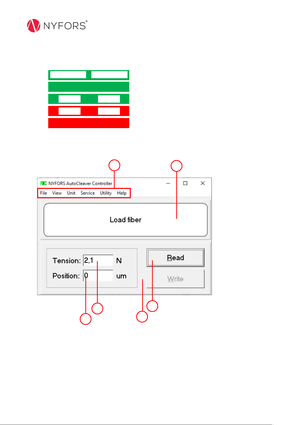
AUTOCLEAVER Controller Software.................................................................................................................................... 27
Using the application ...................................................................................................................................................... 27
Start-up....................................................................................................................................................................... 27
Select COM port.......................................................................................................................................................... 27
Changing the cleaving tension .................................................................................................................................... 28
Adjusting the cleave length ........................................................................................................................................ 28
Complete control description............................................................................................................................................. 29
Main view ....................................................................................................................................................................... 29
File menu ........................................................................................................................................................................ 29
View menu...................................................................................................................................................................... 29
Unit menu ....................................................................................................................................................................... 29
Service menu .................................................................................................................................................................. 29
Utility menu .................................................................................................................................................................... 30
Help menu ...................................................................................................................................................................... 30
Cleaver setup ...................................................................................................................................................................... 30
Setup window ................................................................................................................................................................. 30
Installation of fiber handling parts ..................................................................................................................................... 32
Installation of the adaptor plate..................................................................................................................................... 32
Fujikura FH-100 adaptor ................................................................................................................................................. 33
FITEL S710S adaptor........................................................................................................................................................ 34
Adjusting the cleave length mechanically....................................................................................................................... 34
Installation of the v-groove and height adjustor ................................................................................................................ 35
Definitions........................................................................................................................................................................... 36
Maintenance & Service....................................................................................................................................................... 37
Inspection & Cleaning......................................................................................................................................................... 37
General cleaning ............................................................................................................................................................. 37
Cleaning the v-groove & fixed clamp block .................................................................................................................... 38
Cleaning the v-groove and height adjuster ramp ........................................................................................................... 38
Emptying the fiber waste collector..................................................................................................................................... 38
Cleaver blade ...................................................................................................................................................................... 39
Cleaning the cleaver blade.............................................................................................................................................. 39
Changing cleaver blade position..................................................................................................................................... 39
Replacing the cleaver blade............................................................................................................................................ 39
Verifying & calibrating the load cell.................................................................................................................................... 39
Appendix A.......................................................................................................................................................................... 40
Specifications.................................................................................................................................................................. 40

5
Appendix B.......................................................................................................................................................................... 41
Optional accessories ....................................................................................................................................................... 41
Appendix C.......................................................................................................................................................................... 43
Disposal........................................................................................................................................................................... 43
Appendix D.......................................................................................................................................................................... 44
CE Declaration................................................................................................................................................................. 44
Representatives & Technical Support................................................................................................................................. 45

6
Introduction
General information
The AUTOCLEAVER LDF™is a high precision fiber cleaver, designed for cleaving of large diameter fibers (LDF), using the tension
scribe method. It provides outstanding cleaving performance for solid circular silica fibers, ranging from 230µm to 1000µm in
diameter. The unique and patent pending cleaving process generates typical cleaving angles of less than 0.5 degrees with large
diameter fibers.
The built-in microprocessor controls all parameters and settings, such as clamping, fiber tension and the exact position and
speed of the diamond cleave blade. This control of sensitive parameters guarantees a high cleaving repeatability and accuracy.
The fiber is held in place by a NYFORS LD1fiber holder, which is used to load the fiber into the cleaver. The NYFORS LDF fiber
holder is selected to match the diameter of the fiber coating or jacket. The v-groove clamping block, the distance plate and the
fiber height adjuster are selected to match the diameter of the fiber cladding. The NYFORS LD fiber holder, the distance plate as
well as the v-groove clamp block and the height adjuster work together as a fiber handling kit to ensure optimum cleaving
performance for a particular range of fiber size. These parts are optional when purchasing the cleaver. The parts are easily
exchanged by the operator to set the cleaver up for a different fiber size.
The cleaver is designed to generate a minimum amount of fiber waste, typically less than 20mm. An automatic waste disposal
system removes and collects any hazardous fiber scraps. The cleaver can be connected to a PC that gives access to all
programmable parameters, settings, show information and cleaver status.
If the NYFORS CLEAVEMETER™(interferometer) is used for fiber end inspection after cleaving with the AUTOCLEAVER LDF™,
the fiber under tested will automatically be aligned at the correct distance from the optics and within the coherence length of
the light. The interference pattern will then be shown instantaneously on the screen and be ready for evaluation.
The AUTOCLEAVER LDF™ can be configured for different fiber holder systems, like the Fujikura or Fitel edition cleaver. These
accommodate the Fujikura and Fitel Fusion Splicer Fiber Holders and special linear clamp inserts. See sections for respective
cleaver configurations.
At a glance
•Fully automatic
•Large diameter fiber capability (230 to 1000 µm)
•Low cleave angles < 0.5 °
•Designed for production and laboratory environments
•Operator skill independent and easy to use
•Automatic fiber waste collection
•Long-lasting blade

7
Safety information
Safety warnings and precautions
The AUTOCLEAVER LDF™is a precision instrument and must be handled with care. Therefore, the following
safety rules and general precautions regarding the use and handling of the AUTOCLEAVER LDF™must
always be supervised by the user.
Operational safety warnings
General: The AUTOCLEAVER LDF™must only be used for cleaving optical fibers it was
designed for. Any attempts to use the device for any other purpose could
cause injury to the operator, damage to the cleaver blade or impair the
AUTOCLEAVER LDF™
Fiber waste collector: Never operate the cleaver without the fiber waste collector mounted on the
cleaver because of the risk of injuring to the operator
Eye protection: Always use approved eyeglasses to protect from potential fiber shatter
Connecting cords: Protect the cords from being walked on, being pinched, or sharply bent,
particularly where they connect to any device. Do not jerk, knot, expose the
cords to sources of heat or otherwise abuse the cord. When disconnecting
the cord, pull on the plug –do not pull on the cord. If a cord becomes
damaged in any way, stop using it immediately. Unplug your device during
lightning storms or when unused for long periods of time
Repairs: Do NOT attempt repairs. Do not attempt to take apart, open, service or
modify the devices hardware. Doing so could present the risk of electric shock
or other hazard. Any evidence of an attempt to open and/or modify the
device, including any peeling, puncturing or removal of any labels will void
the limited warranty
Environment: The device is designed for industrial indoor use only. Do not use outdoor or in
explosive environments
Cut hazard: Always handle optical fibers carefully and dispose fiber scraps in a suitable way

8
Transport and storage precautions
•The AUTOCLEAVER LDF™is a precision instrument and must be protected against humidity, vibrations and shock during
transportation and storage.
•When the machine is moved from a cold to warm environment, you should allow about an hour for acclimatization. By this
time, any condensation should have dissipated.
•Always transport the instrument in its original packaging materials, with its transportation safeties and with the marked
side up to prevent damage. Remove fiber handling parts that could come loose during transportation.
External care precautions
•Never use spray cleaner or compressed gas for cleaning the device.
•Never pour liquid cleaner on the instrument. Always put the cleaning solvent on to a clean applicator (i.e. clean, dry cloth
or applicator stick) first and then use the applicator to clean the exposed parts.
•Isopropyl alcohol (IPA) is the recommended cleaning solvent.
•Never use hard objects, acetone, thinner or benzene to clean the instrument.
Upon delivery
Unpacking
•Inspect box for damage prior to opening. If the box appears damaged, please notify the shipping company and NYFORS or
your eventual distributor as soon as possible.
•Remove all contents from the box and verify that all items are included.
•Save packaging material for future use.
Supplied in package
•AUTOCLEAVER LDF™
•USB-stick with PC-software (AUTOCLEAVER Controller) & User Manual
•Getting started: Quick installation guide for AUTOCLEAVER LDF™& Controller software
•Delivery & Calibration Certificate
•2pcs Allen key (1.3mm & 2.5mm)
•RS-232 cable (Null-modem cable)
Required accessories
Please choose proper fiber handling parts according to your fiber holder system and fiber dimensions, and power supply with
country specific adaptor. See Appendix B for a list of available parts and accessories.
Note: included parts in the delivery kits may vary between countries and regions.

9
Overview
External overview
1. Fiber holder clamp vice
2. Mounting rail
3. Front cover
4. Rear cover
5. Fiber waste collector
6. Air pressure regulator for fiber holder clamp vice
7. Start button with LED status
8. Power port (12V)
9. RS-232 port
10. Compressed air inlet (4mm)
11. Product information label
12. Diamond cleaving blade
13. Height adjuster slide ramp
14. V-groove slide ramp
15. Fixed clamp block
4
2
3
5
7
8
9
10
11
15
13
12
14
6
1

10
Flashing characteristics of the start button
A LED in the start button is used to indicate the status of the cleaver:
Green: Standby: Cleaver is ready to be used
Green: Busy: Wait until cleaver is ready
Green: Done: Press start button to continue/reset
Red: Error: Press start button to reset
Red: Fatal error: Disconnect power from cleaver and then
connect it again. If fault remains, contact your service
agent.
Overview of the GUI (graphical user interface)
1. Drop-down menu
2. Progress information window
3. Position setting
4. Tension setting
5. Reads setting from cleaver
6. Writes setting from cleaver
For more information about menus, functions and how-to setup the cleaver via the controller application, see
respective section in the manual.
1
2
3
4
5
6

11
Getting started
Installation
Software system requirements
•Microsoft Windows 2000 SP4 / XP / Vista / 7 / 8 / 10
•PDF Viewer application, e.g. Adobe Acrobat Reader
•Pentium III 900 MHz of faster processor
•256 MB RAM or more
•One free 9-pin serial port (RS-232)
•5 MB available hard disk space
Software installation
To install the controller application on a PC, simply insert the USB into your PC. Open the USB-device on your computer and
click on setup.exe to start the installation program.
Using the application
Start-up
When the application is installed, appropriate short-cuts are created on the user’s desktop and in the start menu. The
application should be started using either of those.
The PC software is intended to be used as an interface to the cleaver when the parameters need to be changed and also to
inform the operator about the progress of the cleaving. The PC is connected to the cleaver via a serial interface (RS-232).
When the application has loaded, the user must first select one proper COM-port from the “File” drop-down list. To read
current tension setting out of the cleaver connected to the PC, click the button “Read” on the controller interface. To change
the tension setting, write the desired tension in the "Tension" box and click "Write".
Cleaver installation
•Unpack the AUTOCLEAVER LDF™and accessories.
•Remove the transportation safety from the cleaver.
•Mount the fiber handling parts required for your application.
•Connect the pressurized air inlet between 5-8 bar (72-116 psi), to the inlet of the cleaver.
•Connect the RS-232 cable from the PC to AUTCLEAVER LDFTM (not required).
•Connect the power supply to an electric outlet and then to the AUTOCLEAVER LDFTM.
•A calibration movement will be initialized.
•The start button will flash green (stand-by) when ready.

12
Cleaving procedure in short
•Place a stripped fiber with its fiber holder on the cleaver.
•Make sure of having the correct fiber length. Incorrect fiber length will produce bad cleaves and can even damage the
clamping device. See separate section in the manual.
•If necessary, use the controller software to change the tension applied.
•Press the start button. The button status LED changes to solid green to indicate that the cleaver is busy.
•Wait until the alignment and clamping are completed, the status LED will be flashing green again.
•Confirm the good clamping condition by pressing the start button again. the status LED changes to solid green to indicate
that the cleaver is busy.
•The cleaving process is executed.
•When the cleaving is finished with success the cleaver beeps twice and the LED on the start button start to flash green
again (busy).
•Remove the cleaved fiber.
The cleaving process can always be aborted by pressing the start button once again after starting the process.
Please observe! Cleaving cannot be executed if the start button flashes “busy” or “error”, reset the cleaver by pressing
the start button once, wait for green “stand-by” flashes.
Description of the cleaving process
1. The operator loads the fiber holder with a fiber
clamped.
2. The operator presses the start button.
3. The height adjuster moves forward to collect
fiber in correct height.
4. The mounting rail with fiber holder adaptor
move in 4mm (direction towards the cleaver
blade), so that the loose fiber end enters the
fiber waste tube.
5. Zero tension is set
6. The v-groove clamp closes.
7. The height adjuster moves back.
8. Mounting rail with fiber holder adaptor moves
out to apply desired tension to the fiber.
9. When the correct fiber tension has been
reached, the cleaver blade moves into cleaving
position.
10. The cleaver blade is engaged and moves
towards the fiber.
11. The load cell indicates when the fiber breaks,
and due to the cleaver design the cleaved end of
the fiber moves away from the diamond
automatically.
12. The cleaver blade retracts to clear the fiber.
13. The mounting rail with fiber holder adaptor moves
outwards 1mm (to protect the cleaved fiber end).
14. The fiber height adjuster moves forward to hold
fiber waste in position.
15. The cleaver blade moves forward and applies a
bending tension to the waste fiber to help it
release from clamp.
16. The vacuum for fiber waste removal starts.
17. The fiber v-groove clamp opens, and the fiber
waste is removed to the waste collector.
18. The fiber height adjuster moves back.
19. The vacuum is switched off.
20. The cleaver blade moves back and down to home
position.
21. The mounting rail with fiber holder adaptor
returns to home position (start position).
22. The operator removes the holder with the cleaved
fiber and the cleaver is now ready for the next
cleave sequence.
Note that there could be some minor deviations from
the cleaving process described above depending on
AUTOCLEAVER LDF™firmware version and/or
configuration.

13
Basic operation
Using the AUTOCLEAVER LDF™
The AUTOCLEAVER LDF™is compatible with the Fujikura FH-40, NYFORS/Ericsson FSU and FITEL S710S fiber holders for fusion
splicers. Choose the correct adaptor plate depending on your fusion splicing system, see Appendix B for options. The fiber is
cleaved to the correct length in the fiber holder and the cleaved fiber can then be directly transferred to the splicer with no risk
of touching or damaging the fiber end.
The cleaver adaptor plate needs to be set up correctly to produce cleaved fibers with correct length, see section Installation of
fiber handling parts for more information. For fine tuning of the cleave length, see information under “Using the application”in
section AUTOCLEAVER Controller Software. See Appendix B for available parts for different fiber sizes. The procedure to change
the v-groove and height adjustor is described in the section Installation of fiber handling parts.
Fiber handling parts
The fiber handling parts are made to fit a specific range of fiber sizes (cladding/coating dimensions) and to support different
fusion splicing systems. For all available parts see Appendix B.
1. V-groove
2. Height adjustor
3. Adaptor plate, NYFORS/Ericsson
4. Adaptor plate, FITEL
5. Adaptor plate, Fujikura
Choose the correct handling parts according to your fiber size.

14
LD fiber holder
The fiber holder consists of three parts; one base plate and two lids. All parts are held together with magnets (6 magnets in the
base plate and 3 magnets on each lid).
If lower clamping force is needed on the fiber, one might reduce the force by removing magnets in the lids (small hexagon
screws on the side of the lids). Remove the center magnet if two magnets will be used (medium force) or keep only the center
magnets on the lids if the lowest possible clamping force is to be used. Do not remove the magnets from the base plate!
Installation of fiber handling parts on the AUTOCLEAVER LDF™
•Install the distance plate with the cylindrical pins on the fiber holder clamp vice (mounted on top of the cleaver). The plate
is held in place by the two pins and magnets.
•Remove the front cover for the v-groove clamp (held in place by magnets) and place the v-groove clamp block (towards
the v-groove clamp cylinders) in position. Make sure the v-groove slide ramp is clean and free of debris.
•Remove the rear cover by unscrewing the two hexagon screws holding it down with the supplied 2.5mm Allen key.
•Place the height adjustor as shown in image, make sure that the spring is located in the small hole at the back of the fixed
clamp block and that the pin from the miniature cylinder is fitted into the hole of the height adjustor.
•Mount the front and rear cover back and tighten the two hexagon screws in the rear cover just until you feel a small
resistance. Do not over tighten.
•This concludes the installation of the fiber handling parts on the AUTOCLEAVER LDF™.
Lid
Base plate

15
Loading fiber into the cleaver
1. Place the fiber in the v-groove of the fiber holder, the fiber should extrude as shown on the image below. Place the two
magnetic lids on the fiber holder base plate to fix the fiber in the holder.
1. Coated fiber 3. Cleaver blade
2. Coating edge 4. Height adjuster
For the cleaver to work properly the loaded fiber must have correct length. An inappropriate length will cause
incorrect cleaving and can in the worst case damage the clamping parts.
2. Strip and clean the fiber. Make sure the stripped part of the fiber is minimum 4 mm to the left of the cleaver blade when the
fiber is loaded into the cleaver.

16
3. Place the fiber holder (with a fiber installed) into the fiber holder clamping vice. The magnets on the fiber holder should be
matching the magnets of the clamping vice. If properly set, the two lids of the fiber holder should be oriented towards the
operator, and the fiber should be located at the bottom of the fiber holder. See images below:
4. The loaded fiber is now ready to be cleaved. Please check that the correct fiber tension is used before starting
the cleaving sequence by pressing the start button.
Fiber holder magnet
Matching magnet
in the clamping
vice

17
Using the AUTOCLEAVER LDFTM –Fujikura Edition
The AUTOCLEAVER LDF™- Fujikura Edition is compatible with the Fujikura FSM-45PM-LDF and FSM-45F-LDF fusion
splicers. The fiber is cleaved to the correct length and since the cleaver accepts the standard Fujikura fiber holders, the
cleaved fiber can be directly transferred to the splicer with no risk of touching or damaging the fiber end. By default, the
cleaver is set up to produce cleaved fibers with 12mm length. For fine-tuning of cleave length, see information under
“Using the application” in section “AUTOCLEAVER Controller Software”. For optional 11mm or 13mm cleave length, see
section “Adjustment of cleaved fiber length” in this manual.
When using the cleaver with Fujikura fiber holders and linear inserts, the upper limit of cladding diameter to be cleaved
is reduced. This version of the cleaver also supports the use of NYFORS LD fiber holders, but please note that it cannot
be used in conjunction with Fujikura fiber holders. For instructions how to use NYFORS LD fiber holders, see the section
“Using the AUTOCLEAVER LDF™”.
Fiber handling parts
The fiber handling parts are made to fit a specific range of fiber sizes (cladding/coating dimensions) and consist of four
different parts. For all available parts see Appendix B.
1. V-groove
2. Height adjuster
3. Linear inserts
4. Fujikura fiber holder (not supplied by NYFORS)
Choose the correct handling parts according to your fiber size.

18
Installation of fiber handling parts on AUTOCLEAVER LDF™
1. Install the linear inserts in the fiber holder clamp vice (mounted on top of the cleaver) as shown in the image
below. Hold the two parts pressed together and slide them into position. The inserts are held in place by the
two pins and magnets.
2. Remove the front cover for the v-groove clamp (held in place by magnets) and place the v-groove clamp block
(towards the v-groove clamp cylinders) in position. Make sure the v-groove slide ramp is clean and free of
debris.
3. Remove the rear cover by unscrewing the two hexagon screws holding it down with the supplied 2.5 mm Allen
key.
4. Place the height adjustor as shown on the image above, make sure that the spring is located in the small hole at
the back of the fixed clamp block and that the pin from the miniature cylinder is fitted into the hole of the
height adjustor.
5. Mount the front and rear cover back and tighten the two hexagon screws in the rear cover just until you feel a
small resistance. Do not over tighten.
This concludes the installation of the fiber handling parts on the AUTOCLEAVER LDF™ - Fujikura Edition.

19
Loading fiber into the cleaver
1. Place fiber in the v-groove of the fiber holder, the fiber should extrude as shown in the illustration below. Close
the lid to secure the fiber position.
1. Coated fiber 3. Cleaver blade
2. Coating edge 4. Height adjuster
Important! For the cleaver to work properly the loaded fiber must have an appropriate length. A wrong
length will cause incorrect cleaving and can in the worst case damage the clamping parts.
2. Strip and clean the fiber. Make sure the stripped part of the fiber is minimum 4 mm to the left of the cleaver
blade when the fiber is loaded into cleaver.

20
3. Place the Fujikura fiber holder with the stripped and cleaned fiber on the adaptor plate. Please check that the
fiber end is in the correct position and that the correct fiber tension is used before continuing to the next step.
4. Push on the clamp vice sideways (or press the start button once) to activate the clamp vice. The linear clamp
closes and holds the fiber firmly.
5. Open the lid of the Fujikura fiber holder.
6. The loaded fiber is now ready to be cleaved. Press the start button to start the cleave sequence.
7. When the fiber is cleaved and the fiber has returned to its initial position, close the lid of the Fujikura fiber
holder.
8. Now push again sideways on the clamp vice (or press the start button). The linear clamp opens and the fiber
holder with the fiber clamped can be removed.
9. Remove the fiber holder with the cleaved fiber and place it in the splicer.
The AUTOCLEAVER LDF™is now ready for the next cleave.
Table of contents