Struers Discotom-60 User manual
Discotom-60/-65
Instruction Manual
Manual No.: 15907001
Date of Release: 09.09.2013

Discotom-60 /-65
Instruction Manual
Table of Contents Page
User’s Guide.............................................................................1
Reference Guide.....................................................................35
Quick Reference Guide...........................................................61
Always state
Serial No and Voltage/frequency if you have technical questions or when ordering spare parts.
You will find the Serial No. and Voltage on the type plate of the machine itself. We may also need the
Date
and
Article No of the manual. This information is found on the front cover.
The following restrictions should be observed, as violation of the restrictions may cause cancellation of
Struers legal obligations:
Instruction Manuals:
Struers Instruction Manuals may only be used in connection with Struers equipment
covered by the Instruction Manual.
Service Manuals:
Struers Service Manuals may only be used by a trained technician authorised by Struers.
The Service Manual may only be used in connection with Struers equi
pment covered by the Service Manual.
Struers assumes no responsibility for errors in the manual text/illustrations. The information in this manual is
subject to change without notice. The manual may mention accessories or parts not included in the present
version of the equipment.
Original instructions.
The contents of this manual are the property of Struers. Reproduction of any part of
this manual without the written permission of Struers is not allowed.
All rights reserved. © Struers
2013.
Struers A/S
Pederstrupvej 84
DK
-2750 Ballerup
Denmark
Telephone +45 44 600 800
Fax +45 44 600 801
Discotom-60 /-65
Instruction Manual
Discotom-60/ -65
Safety Precaution Sheet
To be read carefully, before use
1. The operator(s) should be fully instructed in the use of the machine and
its cut-off wheels according to the Instruction Manual and the
instructions for the use of cut-off wheels.
2. The machine must be installed in compliance with local safety
regulations.
3. The machine must be placed on a safe and stable support table. All
safety functions and guards of the machine must be in working order.
4. Use only intact cut-off wheels. The cut-off wheels must be approved for
use with rotational speeds between 1000 and 3460 rpm.
5. The machine is not for use with saw-blade type cut-off wheels.
6. Observe the current safety regulations for handling, mixing, filling,
emptying and disposal of the additive for cooling fluid.
7. The workpiece must be securely fixed in the quick-clamping device or
similar. Large or sharp workpieces must be handled in a safe way.
8. Do not work on or around cutting table when the table is repositioned
using the Y-table positioning joystick.
9. To achieve maximum safety and lifetime of the machine, use only
original Struers consumables.
10. The cutting handle should be lowered slowly and carefully, in order to
avoid breaking the cut-off wheel.

Discotom-60 /-65
Instruction Manual
11. Struers recommends the use of an exhaust system as the materials
being cut may emit harmful gasses or dust.
12. The machine emits only moderate noise. However, the cutting process
itself may emit noise, depending on the nature of the workpiece. In
such cases, the use of hearing protection is recommended.
13. The machine must be disconnected from the mains prior to any service.
14. Use of working gloves is recommended as workpieces may be both
very hot and produce sharp edges. Wearing of gloves is also
recommended when flushing and cleaning the machine.
15. Struers recommends the use of safety shoes when working with heavy
samples.
16. Use of safety goggles is recommended when using the flushing hose.
17. If any of the cutting-chamber hood springs are damaged (at the rear of
machine), they must be replaced before the machine is used again.
18. When a recirculation cooling unit is used, observe the current safety
regulations for handling, mixing, filling, emptying and disposal of the
additive for cooling fluid.
Do not use flammable cooling fluid.
19. When lifting the machine using a forklift, lift from front or rear - never lift
the machine from the side.
20. When lifting the machine using lifting straps, ensure that the straps are
crossed and do not press on the sides of the machine.
1. Prior to any service, disconnect the machine then wait until residual
potential on the capacitors is discharged.
2. Do not cycle mains power more than once every three minutes.
Damage to the frequency converter will result.
Discotom-65
The equipment should only be used for its intended purpose and as detailed in the Instruction Manual.
The equipment is designed for use with consumables supplied by Struers. If subjected to misuse, improper
installation, alteration, neglect, accident or improper repair, Struers will accept no responsibility for
damage(s) to the user or the equipment.
Dismantling of any part of the equipment, during service or repair, should always be performed by a qualified
technician (electromechanical, electronic, mechanical, pneumatic, etc.)

Discotom-60 /-65
Instruction Manual
1
User’s Guide
Table of Contents Page
1. Getting Started ............................................... 3
Checking the Contents of the Packing Box........................................3
Getting Acquainted with Discotom .....................................................4
Noise Level ........................................................................................5
Power Supply.....................................................................................6
Connection to an External Exhaust System.......................................8
Connecting a Recirculation Cooling Unit............................................9
2. Basic Operation..............................................10
Using the Controls............................................................................10
Front Panel Controls of Discotom...........................................10
Front Panel Controls ........................................................................11
Cooling Valve Positions ...................................................................12
Flush Hose.......................................................................................12
Cleaning of Flush Hose Nozzle........................................................12
Setting the Language.......................................................................13
Moveable Table................................................................................13
Y-Table ...................................................................................13
Reading the Cutting Display.............................................................14
Changing Cutting Mode and Cutting Parameters.............................15
Changing Cutting Mode..........................................................15
Changing Cutting Parameters.................................................16
Using Motor Load and Temperature Display..........................22
Automatic Feed Speed Control...............................................22
Overload Protection .........................................................................23
Fitting or Changing the Cut-off Wheel..............................................24
Clamping the Workpiece..................................................................24
Positioning the Cutting Table...........................................................24
Starting/Stopping the Cutting Process .............................................25
Automatic Cutting....................................................................25
Manual Cutting........................................................................26
Combining Manual and Automatic Operation.........................26
Stop Modes......................................................................................27
Relative Stop Position............................................................27
Absolute Stop Position ..........................................................28
Automatic Stop......................................................................29
Variable Motor RPM (D-65 only)......................................................30
Recommended Settings:.........................................................30
Cleaning...........................................................................................32
Flushing the Cutting Chamber................................................32

Discotom-60 /-65
Instruction Manual
2
3. Routine Maintenance.......................................33
Daily Service ....................................................................................33
Weekly Maintenance........................................................................33
Monthly Maintenance.......................................................................33
Replacing the Cooling Water..................................................33
Yearly Service..................................................................................34
Inspection of Guard.................................................................34

Discotom-60 /-65
Instruction Manual
3
1. Getting Started
In the packing box you should find the following parts:
1 Fork spanner (24 mm) for cut-off wheel
1 Connector pipe for water outlet
3 Elbow pipes for water outlet
1 Outlet hose 2 m,
for connection to external cooling unit
3 Hose clamps, 35-60 mm
1 Grease for maintenance/lubrication of the spindle
1 Oil for maintenance of cutting table
1 Set of Instruction Manuals
Remove the bolts from all of the transport brackets that secure the
Discotom to its transport pallet.
Remove the brackets.
Discotom should be placed on a table strong enough to support a
minimum of 171 kg/ 377 lbs.
Struers recommends the use of the Table Unit, which is designed for
use with Discotom machines, see “Accessories”.
Checking the Contents
of the Packing Box
Unpacking Discotom
Placing Discotom

Discotom-60 /-65
Instruction Manual
4
Take a moment to familiarise yourself with the location and names of
the Discotom’s components.
Cutting handle
Control panel
Y-table joystick
Emergency stop
Cooling valve
Main power switch
Cut-off wheel locking handle
Getting Acquainted
with Discotom
Front View
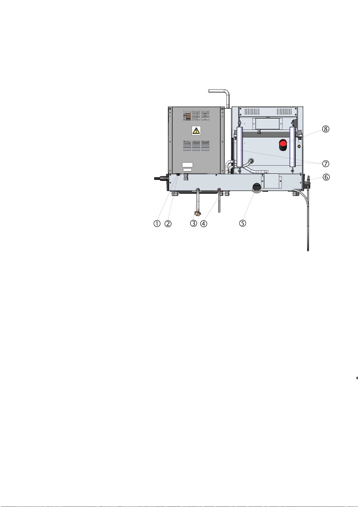
Side view, right
Discotom-60 /-65
Instruction Manual
5
Cooli unit connection
Service socket (RS232)
Water intlet
Drainage hose
Water outlet flange
Flushing hose
Cutting chamber hood springs
Exhaust connection
Approx. 67 dB (A) measured at idle running, at a distance of
1.0 m/39.4” from the machine.
Rear View
Noise Level

Discotom-60 /-65
Instruction Manual
6
First check that the mains voltage corresponds to the voltage
stated on the type plate on the side of the machine.
Discotom-60 is factory mounted with an electric cable.
Mount a plug on the cable according to the following:
EU cable UL cable
L1Brown
L2Black
L3Black or grey
Earth Yellow/green
Neutral Blue (Not used)
L1Black
L2Red
L3Orange/ turquoise
Earth Green (or Yellow/green)
Neutral White (Not used)
Check that the cut-off wheel rotates in the direction indicated by the
arrow on the cut-off wheel guard. If the direction of rotation is
incorrect:
EU cable UL cable
Switch two of the phases Switch phases L1and L2
Power Supply
Discotom-60
Direction of the Cut-off Wheel
Discotom-60 /-65
Instruction Manual
7
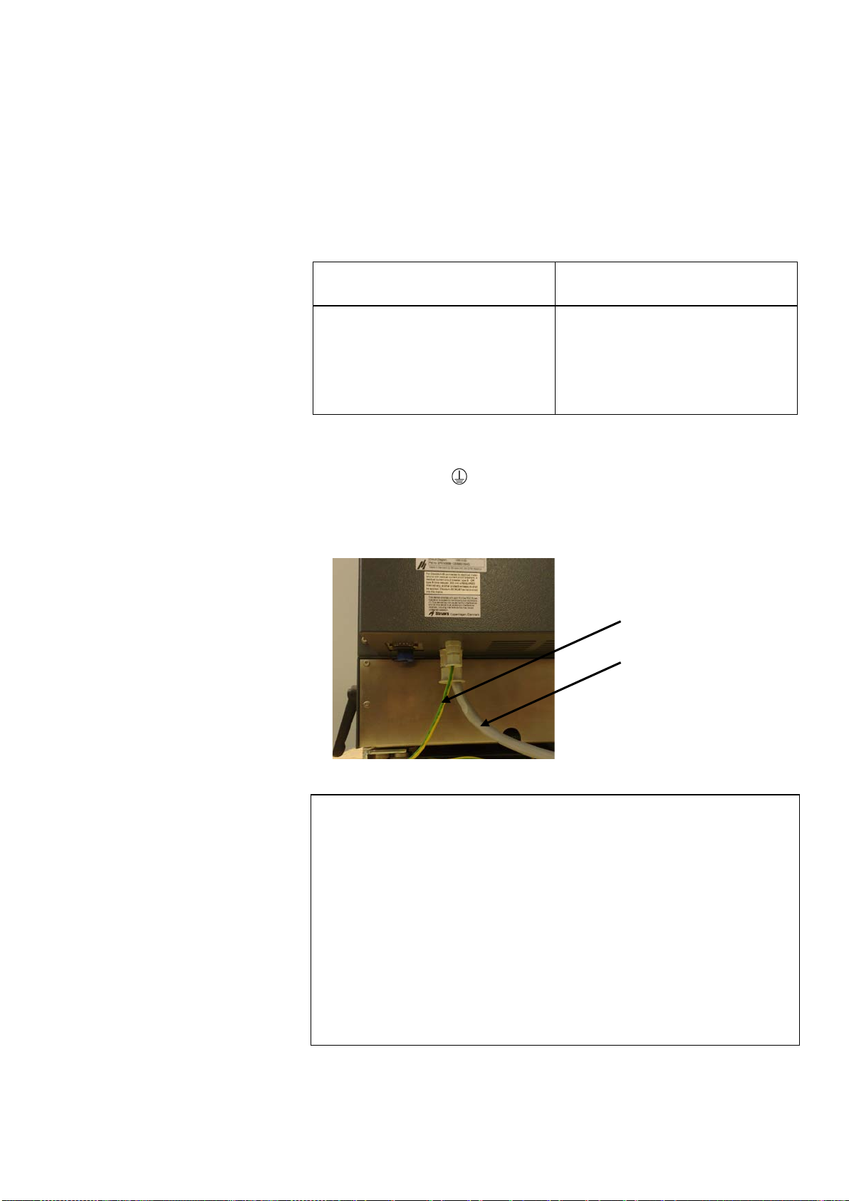
Discotom-65 is factory mounted with an electric cable and an
additional wire for earth connection. Both MUST be hard-wired into
the mains (ref. EN 50178 / 5.2.11.1):
EU cable UL cable
L1Brown
L2Black
L3Black or grey
Earth Yellow/green
Neutral Blue (Not used)
L1Black
L2Red
L3Orange/ turquoise
Earth Green (or Yellow/green)
Neutral White (Not used)
The second Protective Earth must be earthed by connection to a
terminal marked or PE.
Alternatively, use a system whereby there is an automatic
disconnection of the supply in case of loss continuity of the
protective conductor.
Both requirements refer to the European standard EN 50178 / 5.2.11.1.
Similar standards apply in North America.
Discotom-65
Important:
For Electrical Installations with Residual Current Circuit Breakers
For Discotom-65 connected to electrical installations with residual current
circuit breakers, a residual current circuit breaker,
type B time delayed, 30 mA is REQUIRED
(ref. EN 50178 / 5.2.11.1).
For Electrical Installations without Residual Current Circuit Breakers
The equipment must be protected by an insulation transformer
(double-wound transformer)
Please contact a qualified electrician to verify which option is suitable for the
local installation setup.
Protective earth
Electric cable
Discotom-60 /-65
Instruction Manual
8
Struers recommends the use of an exhaust system, as workpieces
may emit harmful gases when cut. The exhaust system will also
reduce the level of water condensation on the sides of the protection
guard.
To connect the Discotom to an exhaust system:
Remove the red cap from the flange.
Mount an exhaust hose from your local exhaust system onto the
flange (50 mm (approx. 2") dia.).
Connection to an External
Exhaust System
Important
If no exhaust is connected, damp air (produced by the cutting process) may
escape from the cutting chamber and penetrate into other areas of the
cabinet. This may cause damage to components and shorten the lifetime of
the machine.
Discotom-60 /-65
Instruction Manual
9
To ensure optimal cooling, Discotom can be fitted with a Cooli unit.
Cooling System 5 is a Cooli configuration designed for use with
Discotom.
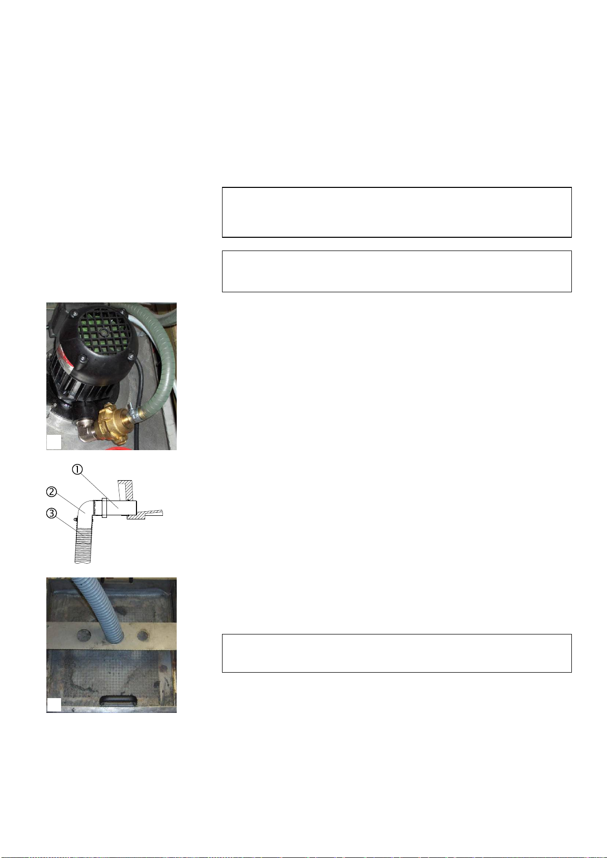
To connect the Discotom to a Recirculation Cooling Unit:
Plug the Cooli control unit’s communication cable into the
Discotom’s control socket.
Connect the water inlet hose to the Cooli pump using the quick
coupling (A).
Connect the other end of the hose to the Discotom water inlet.
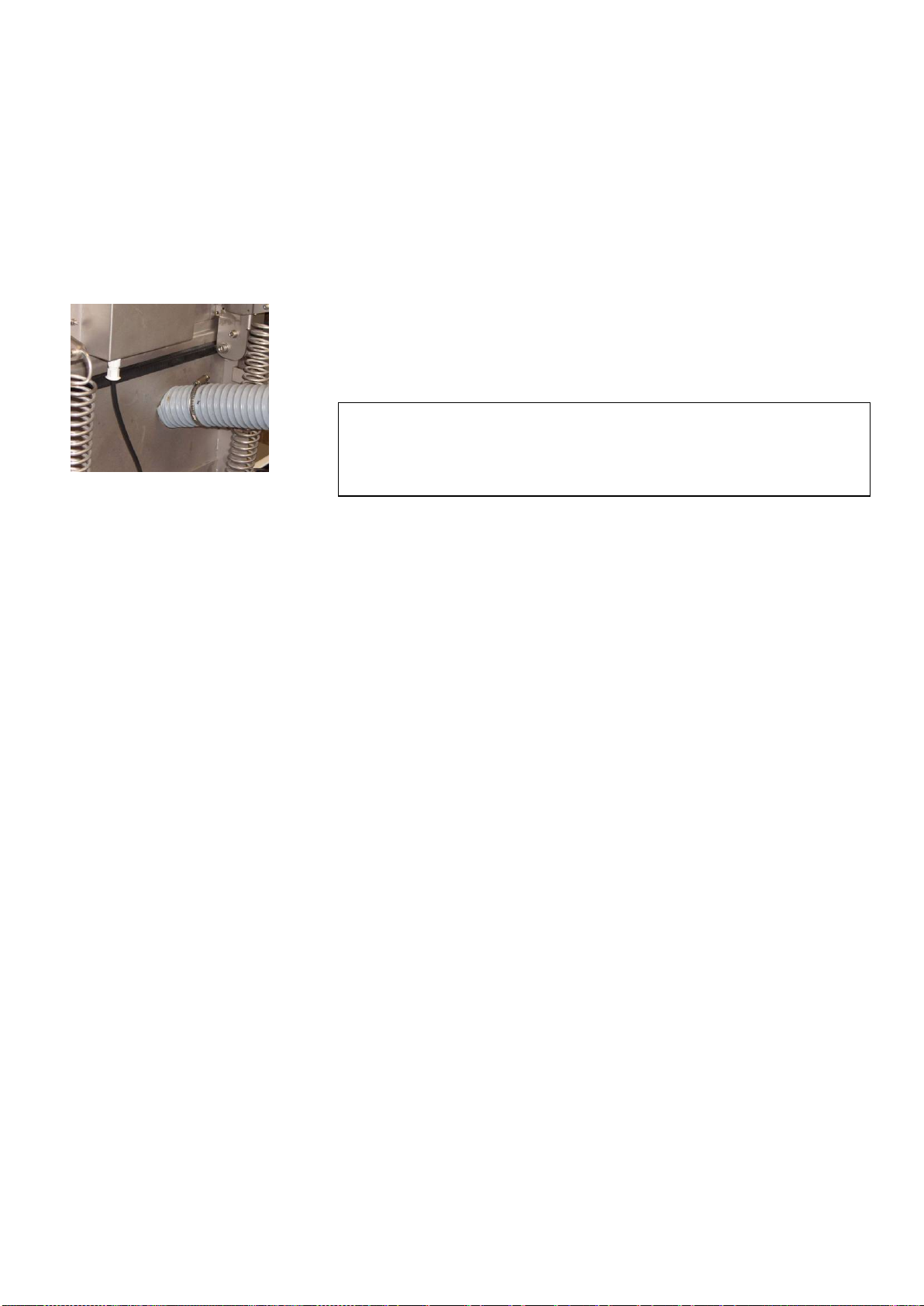
Insert the connector pipe in the water outlet on the back of
Discotom and mount the 90° elbow pipe . Lubricate the sealing
ring with grease or soap to facilitate insertion. (Use the other
elbow pipe if more suitable).
Mount the outlet hose onto the elbow pipe and clamp using a
hose clamp.
Check that the outlet hose slopes downwards when connected. If
necessary adjust the length of the hose.
Insert the other end of the hose into the mounting hole in the
bracket on top of the Cooli filter unit (B).
Connect the cooling unit to the mains power supply.
Place the drainage hose in the tank of the Cooling Unit or lead to
drain.
Connecting a Recirculation
Cooling Unit
Note:
Cooling System 5 includes a static filter.
For intensive use, and for materials generating a lot of swarf,
a bandfilter such as Coolimat-200 is recommended.
Note
Before connecting the cooling unit to the Discotom, follow the instructions in
the Cooling Units Instruction Manual to prepare it for use.
IMPORTANT
Before connecting, check that the mains voltage corresponds to the voltage
stated on the type plate on the side of the machine.
Drainage Hose
A
B
Discotom-60 /-65
Instruction Manual
10
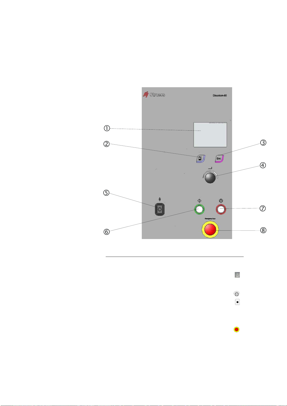
2. Basic Operation
Control name Symbol
DISPLAY
MENU KEY..............................................................................
ESCAPE ..............................................................................ESC
MULTI-FUNCTION KNOB .....................................................
JOYSTICK .............................................................................
START....................................................................................
STOP......................................................................................
EMERGENCY STOP..............................................................
Using the Controls
Front Panel Controls
of Discotom
Discotom-60 /-65
Instruction Manual
11
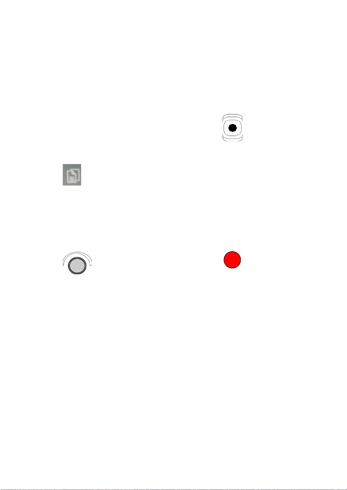
Name Item Function
Name Item Function
DISPLAY
The Discotom’s display.
JOYSTICK
Move up-or down to position
the Y- table.
MENU KEY
Menu dependent multi-function
key. See the bottom line of the
individual screens.
START
Starts the machine and
recirculation unit and/or band
filter.
ESCAPE Moves one step backward in
menus. If modified parameters
have not been stored, changes
are lost.
STOP
Stops the machine and
recirculation unit and/or band
filter.
MULTI-
FUNCTION
KNOB
Push knob to select function.
Turn knob to adjust settings.
Push knob to store modified
settings.
EMERGENCY
STOP
Push the red button to stop.
Pull the red button to release.
Front Panel Controls
Discotom-60 /-65
Instruction Manual
12
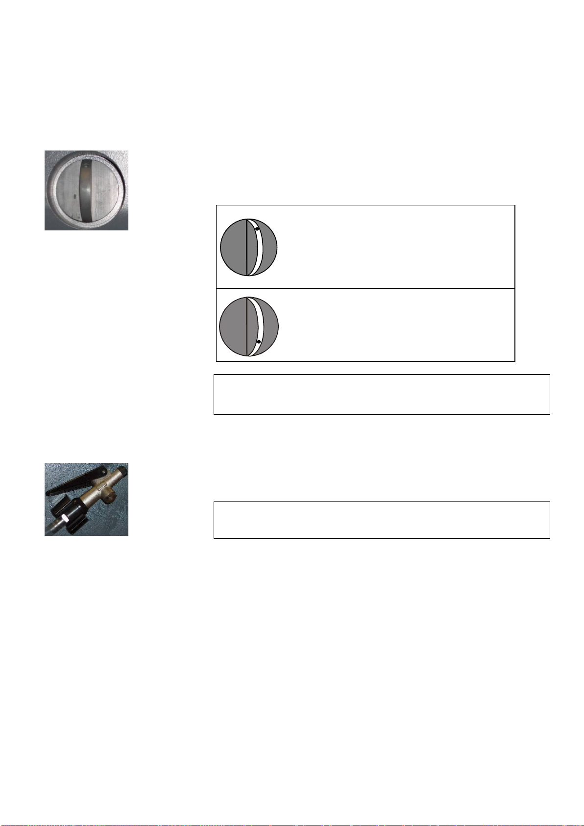
The cooling valve switches the flow of cooling fluid between the
cutting chamber (cutting) and the flushing hose (cleaning).
During cutting the valve is placed in the vertical position to cool the
cut-off wheel. During cleaning the valve is turned clockwise to divert
cooling fluid to the flushing hose.
Turn the valve anti-
clockwise (dot to top)
for cut-off wheel
cooling.
Cutting position
Turn the valve
clockwise (dot to
bottom) for cleaning. Cleaning position
Press down the lever, on the top of the flush hose, to open the
hose’s on/off valve and to adjust the flow of water.
For instructions on how to use the flushing hose when cleaning the
Discotom, see “Cleaning”.
The flush hose nozzle may collect swarf, inhibiting the flow of cooling
fluid.
To clean, unscrew nozzle head and rinse under clean water.
Cooling Valve Positions
Please Note
After cleaning, turn cooling valve back to vertical position. START can
not be activated unless the cooling valve is in the cutting position.
Flush Hose
IMPORTANT
Do not move the cooling valve to the cleaning position
until the flush hose is pointing inside the cutting chamber.
Cleaning of Flush Hose Nozzle
Discotom-60 /-65
Instruction Manual
13
When the Discotom is started for the first time, a screen display
prompts selection of a preferred language.
To change the language:
From the CUTTING menu, press MENU
button once to
select CONFIGURATION Menu.
Turn knob to navigate between parameters in the
CONFIGURATION Menu.
Push knob to select LANGUAGE. A pop-up menu
appears.
From the pop-up menu, select your preferred language
and enter the setting by pushing the knob.
Press ESC button to move from CONFIGURATION Menu
to Cutting menu.
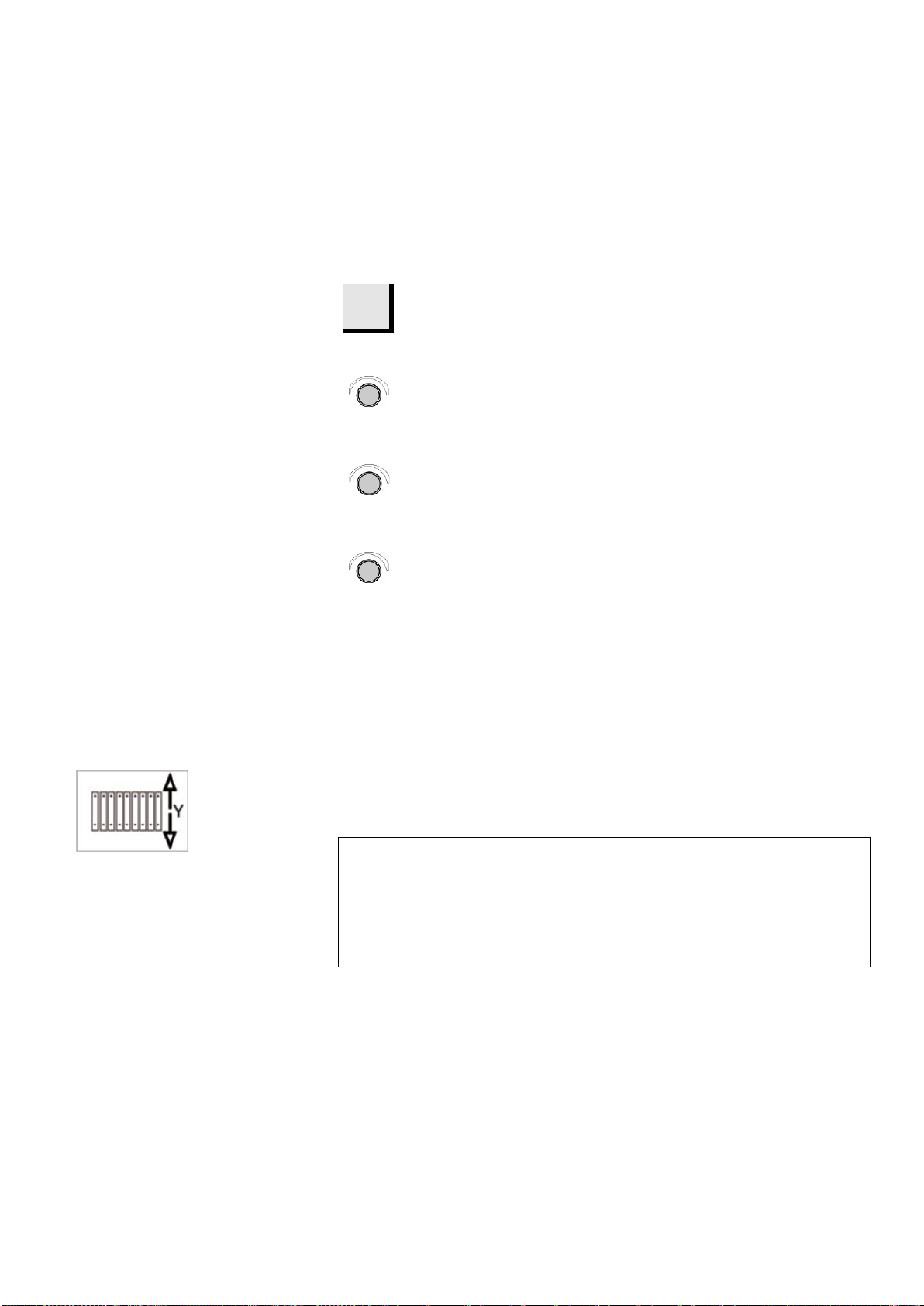
The Y-table is a motor driven, movable table. Using the joystick (see
“Control Panel Functions”) the table can be moved backwards and
forwards. The Y-table is especially useful for cutting wide
workpieces.
Setting the Language
Moveable Table
Y-Table
Note:
When Discotom is switched on, the cutting table will move to the front
reference position (the latest position of the cutting table).
However, when Discotom has been switched on and off 10 times, the
cutting table will firstly move to the front of the cutting chamber and then to
the back. This automatic movement helps keep the two guide shafts free of
cutting swarf.

Discotom-60 /-65
Instruction Manual
14
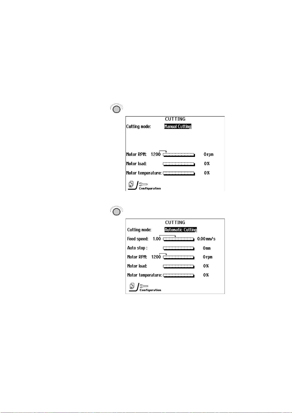
The Cutting Display displays three types of information:
A: Cutting Mode
B: Cutting Parameters, and
C: Motor Information
The top area of the display (A) displays the selected Cutting Mode:
Manual Cutting or Automatic Cutting mode.
In Automatic Cutting mode, the middle area of the display (B)
displays information about the Cutting Parameters: Feed speed, Stop
position and Motor RPM (D-65 only).
The Cutting Parameters can be set both before and during cutting.
The set value is displayed to the left of the bar graph. The actual
value (during cutting) is displayed to the right of the bar graph.
The bottom area of the display (C) displays Motor information: Motor
load and Motor temperature. The values displayed are in relative (%)
values.
Reading the Cutting Display
Cutting Mode
Note:
In Manual Cutting mode, Cutting Parameters are not displayed.
This area of the display will be blank.
Cutting Parameters
Motor Information
B
A
C
Discotom-60 /-65
Instruction Manual
15
The Discotom has two cutting modes: Manual and Automatic.
To toggle between these two modes:
Turn knob to highlight cutting mode.
Push knob to toggle between the two cutting modes.
Changing Cutting Mode and
Cutting Parameters
Changing Cutting Mode

Discotom-60 /-65
Instruction Manual
16
In automatic cutting mode the Discotom applies the selected cutting
parameter values for: Feed speed, Stop mode and Motor RPM (D-65
only).
To adjust the values of these parameters:
Turn the knob to highlight a selected cutting parameter.
Push the knob to allow editing of the highlighted parameter. Turn
the knob to change the value of the parameter.
Push the knob to store the new value.
Actual values of the cutting parameters: Feed speed, Stop position
and Motor RPM (D-65 only) are displayed to the right of the columns
(A).
Turn the knob to change the value of the selected cutting parameter.
The arrow above the column will move to reflect the new setting (B).
Changing Cutting Parameters
Turn knob to select Cutting
Parameter.
Push knob to allow editing of Cutting
Parameter.
Turn knob to adjust value.
Push knob to store new value.
B
A
This manual suits for next models
1
Table of contents
Languages:
Other Struers Cutter manuals


