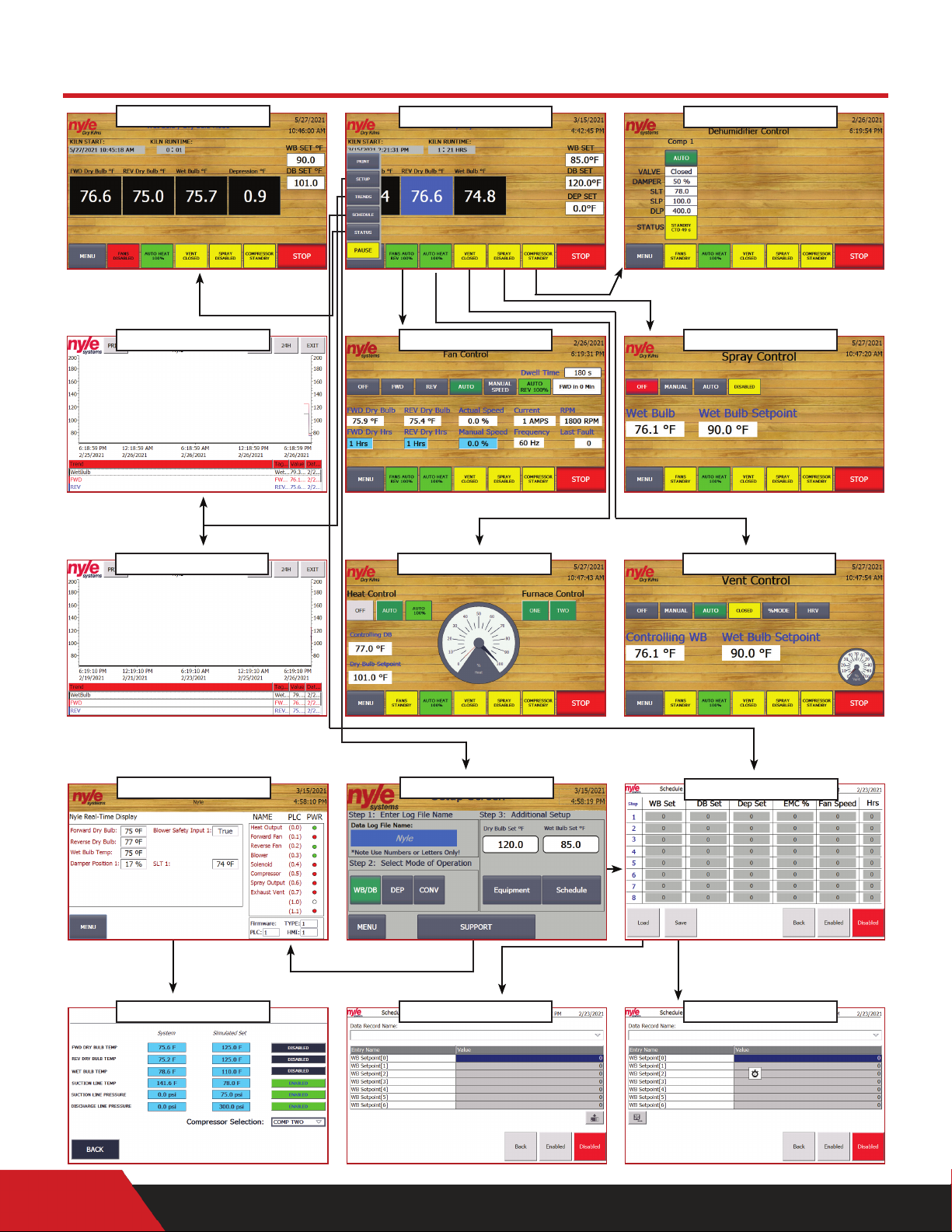
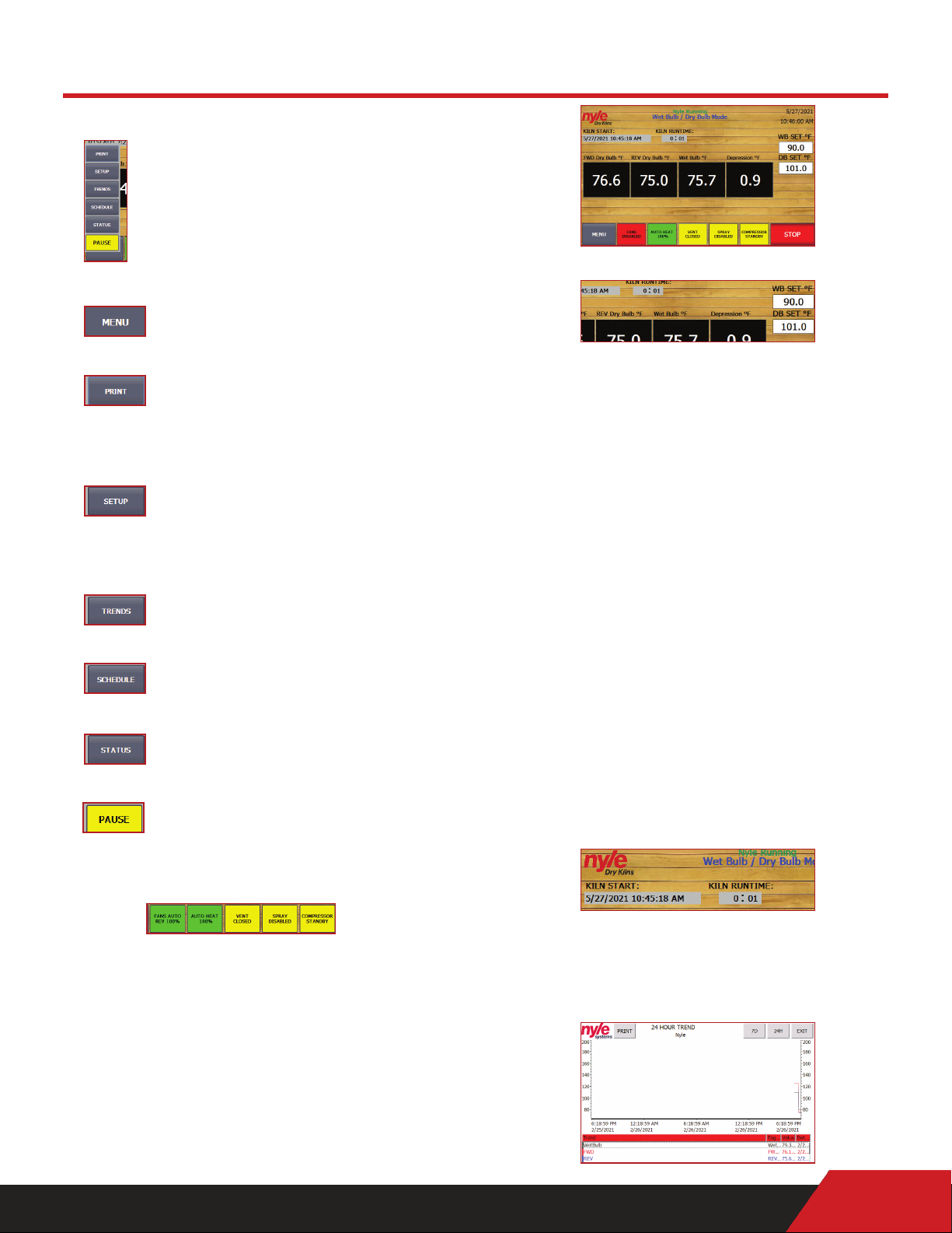
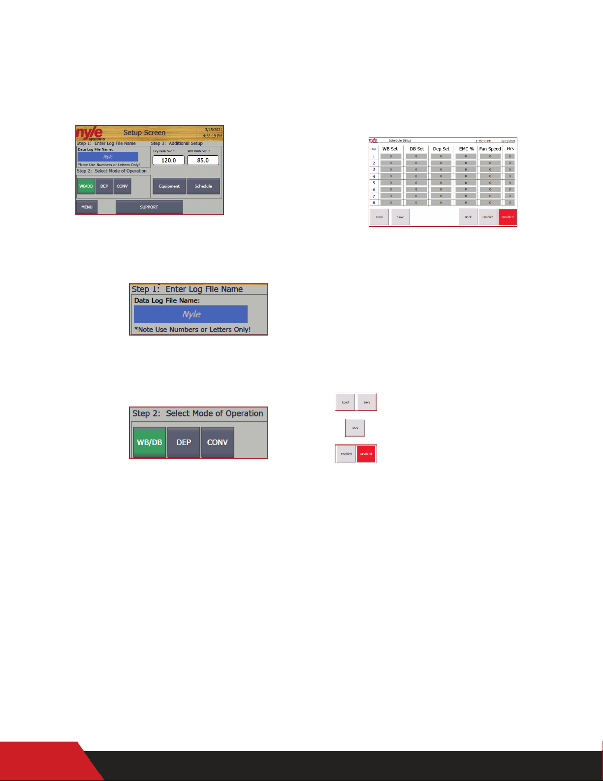
Nyle NSC-100 User manual

www.nyle.com - kilnsales@nyle.com - (800) 777-6953
User Manual
NSC-100 Kiln Controls
© 2021 Nyle Dry Kilns
NSC-100 Manual REV 2021.01

Table of Contents
Safety Guidelines.................................................................................................................................1
Screen Outline .................................................................................................................................... 2
Quick Start Guide .............................................................................................................................. 3
Menu Bar .................................................................................................................................................................. 3
Status Screen ......................................................................................................................................................... 3
Trend Screen ......................................................................................................................................................... 3
Setup Screen .......................................................................................................................................................... 4
Schedule Screen .................................................................................................................................................... 4
Schedule Controls.............................................................................................................................. 5
Entering a Schedule.............................................................................................................................................. 5
Saving a Schedule................................................................................................................................................. 5
Loading a Saved Schedule ................................................................................................................................ 5
Data Logging ..................................................................................................................................... 5
Starting a Data Log ............................................................................................................................................. 5
Retrieving a Data Log ....................................................................................................................................... 5
Remote Access .................................................................................................................................. 5
Password Change & VNC/WEB Remote Access Conguration ...................................................... 5
Setting up Remote Access with VNC Viewer ....................................................................................... 6
Warranty ........................................................................................................................................... 7
Control Wiring ................................................................................................................................... 8
PLCPowerWiring................................................................................................................................12
Slice Relay Wiring .............................................................................................................................. 13
Inputs Wiring ................................................................................................................................... 14

1
Read through entire manual before installing, operating, or servicing this unit.
Failure to follow any steps or guidelines could result in personal injury, death, destruction
of property or may cause the unit to become inoperable. This manual must be kept with the unit at all times.
Refrigerant!
• Unit contains refrigerant under high pressure.
Refrigerant must be recovered to relive pressure
before servicing.
• DO NOT use unapproved refrigerants, substitutes
or additives.
• Failure to abide by these guidelines can result in
death, injury and property damages.
• Contact Nyle’s service department for more information
on refrigerant options.
Electrical Shock!
• Turn off power to unit
before service.
• Make sure wires are labeled
before disconnecting.
• Test unit after reconnecting
wires.
• Failure to do the above could result in death or injury.
High Temperatures!
• Kiln chamber can reach
internal temperatures of
over 90°F. working in these
temperatures can cause heat stroke and minor burns.
• Pregnant women, children, the elderly and those
with signicant health issues are at higher risk of heat
stroke and must be supervised in high temperatures.
• Kiln operators should check for temperature and
take proper safety precautions before entering the
kiln chamber.
Safety Guidelines
Precautions
Do not operate if the unit or any of its parts:
• Have been exposed to re.
• Have been submerged in or exposed to excessive
water.
• Has signicant interior or exterior damage.
If any of the above are suspected make sure to have
your unit serviced by a qualied professional before
continuing operation.
Electrical Grounding
The unit must be grounded.
Failure to ground the unit will result in unreliable
performance or an inoperative unit.You can ground
the unit by connecting the unit to a grounded
metal, permanent wiring system. Make sure the
unit is in accordance with national and local electrical
codes. If you don’t know the building codes in your
area or need more information, please contact your
municipal oce.
• DO NOT purge or
pressurize this system with
oxygen to test for leakage.
Using oxygen may cause
explosive reaction.
Explosion Hazard!

2
Screen Outline
Compressor Screen
Status Screen Menu Bar
24 HR Trend Screen Fan Screen Spray Screen
7 Day Trend Screen Heat Screen Vent Screen
Support Screen Setup Screen Schedule Screen
Simulator Screen Load Screen Save Screen

3
Quick Start Guide
Menu Bar
From the menu bar, the user can
navigate to 3 function screens;
status screen, trend screen and setup
screen.
Function Buttons:
The “Menu” button will toggle the
function buttons to access the func-
tion screens
The “Print” button allows you to print
the screen you are on. Note: a printer
must be installed and congured to
your control in order for this feature to
work.
The “Setup” button will bring you to
the setup screen where you can enter
the log le name, kiln mode as well as
naviagte further to the schedule and
support screens.
The “Trend” button will bring you to
the trend screen where you can see
the graphs of the kiln cycle.
The“Schedule”button will bring you to
the schedule screen where you can see
and edit the kiln’s schedule.
The “Status” button will bring you to
the status screen where you can see
the status of the kiln cycle.
The“Pause”button allows you to pause
the kiln cycle at any point and be able
ro resume from where you left o.
Equipment Buttons:
The user can also access the ve equipment
sceens along the botton. These screens are
the fan, heat, vent, spray and compressor. Thes
buttons will take the user to the corresponding
screens but also display their current conditions
Status Screen
From the status screen, the user can see all of
the real time kiln conditions during the drying
cycle.
Temperature & Setpoints:
This section shows the actual temperatures;
FWD - The temperature of the dry bulb sensors in
front of the fan wall (if fans are moving in the forward
position)
REV - The temperature of the dry bulb sensors
behind the fan wall (If fans are moving in reverse)
WET - The average temperature of the wet bulb
sensors.
Wet Bulb > Wet Bulb Setpoint = Vents will open
Wet Bulb < Wet Bulb Setpoint = Vents will close
Note: the FWD or REV value that is highlighted in blue
indicates which direction the fans are moving. In this
case they are running in reverse.
Dry Bulb Set points & Wet Bulb Set points
are the current set points used to control. If
the schedule is enabled, schedule values are
shown on the schedule screen. If the schedule
is disabled, these values become“live editable”
and the controller will follow the values you
enter here.
Kiln Start & Runtime:
This section logs the start time of the cycle and
how long its been running for.
Trend Screen

4
From the trend screen, the user can see all of
the graphs for the kiln cycle. Note: the user can
toggle between a 24 hour & 7 day view by usu-
ing the buttons on the top right of the screen.
Setup Screen
From the Setup screen, the user can set the
Log File Name, Select the Mode of operation
and navigate to the Schedule and Support
Screens.
Log File Name:
Under this step the user can select the name
that the kiln cycle will be recorded under in
the data log.
Select Mode of Operation:
Under this step the user can select the mode
of operation for the kiln. The user can choose
from three modes of operation; Wet Bulb/ Dry
Bulb, Depreciation or Conventional.
Wet Bulb / Dry Bulb Mode: This mode con-
trols our standard dehumidication system
via a wet bulb temperature inside the kiln.
The controlling dry bulb (dry bulb based
on fan direction) controls the heat output
and the exhaust vents.
Depression Mode: This mode controls the
heat based on the controlling dry bulb
(dry bulb based on fan direction). Either
our standard dehumidications system or
the exhaust vents are controlled via the
depression inside the kiln (Controlling Dry
Bulb Temp – Wet Bulb Temp).
Example: 140F Dry Bulb – 100F Wet Bulb = 40F Depression
Conventional Mode: This mode controls
the heat based on the controlling dry bulb
(dry bulb based on fan direction). The ex-
haust vents are controlled by the wet bulb
temperature.
Schedule Screen
The Schedule Screen has 8 time based steps.
For each step you can set;
WB Set - Will call Vent to open when Wet Bulb actual is
above this value and to close when below.
DB Set - Will call for Heat to come on when Dry bulb is
below this value and will shut o when above.
Fan Speed - Percentage of VFD output. Can be 100%
with wood MC above 28% and 80% when below 28%
Hrs - Time to run in this step before progressing to the
next step.
Current schedule can be Saved or Loaded
from memory.
Takes you back to the Setup Screen.
These buttons enables / disables the
Schedule function. When“Enabled”is green,
the controller will follow the schedule as
per the schedule screen. When “Disabled” is
red, the controller will follow the Dry bulb
set point and Wet bulb set point, settable
“live”on the home screen.
Incase of kiln power failure during schedule
If your kiln experiences power failure during a
schedule your kiln will power back up and start
the schedule over. To resume where you left o
you must;
- Stop the kiln
- Changes the completed steps“Hrs” to 0
- Start the Kiln
Note: Be sure to save this schedule under a dierent
name

5
Data Logging
Entering a Schedule
A new schedule can be entered either manually or
by pressing the LOAD button. If no previous schedules
have been saved, the HMI will not be able to load
a schedule into the PLC control. Navigate to the
SETUP screens and then to Schedule to begin the
schedule control process.
On the main schedule screen the full 8 step schedule
that is currently loaded into the PLC will be displayed.
To change values in that schedule simply touch on
the desired set-point, enter a new value, and press
the return key. Once satised with the currently
loaded schedule, press the “Enabled” key to run via
the automatic set point changing schedule control.
Saving a Schedule
If you would like to SAVE a schedule for later use, rst
enter into the PLC as described above. Once you are
satised with the currently loaded schedule press
the“Save”button to display the save schedule interface.
You may verify the schedule about to be saved by
pressing the up and down arrows displayed on the
left of the screen. Press the arrow facing left to begin
the save process. A pop-up will appear verifying the
save command. Press “Yes” followed by “Save As” to
rename the schedule in a way that makes sense for
the schedule. See image above.
Loading a Saved Schedule
Once a schedule has been saved, it can be reused
over and over for ecient drying processes. To
load a schedule, navigate to the schedule setup
screen. Press the“Load”button to begin the loading
process. Press the left arrow once, and press on the
schedule you want to load into the PLC. Pressing
the “Back” button pushes the new schedule into
the PLC for runtime. Verify the loaded schedule
before pressing the “Enabled” key.
Starting a Data Log
Logging data with the NSC100 control is simple.
Just by entering a LOTID and pressing the start button
automatically begins the data logging process. The
control is capable of storing up to 2 complete cycle
logs in most cases. Once the data log storage space
has been lled up on the PLC, an operator message
will appear requiring the download and clearing of
the logs through the retrieval system.
A log bypass option is available if the data log is not
required. To access this operation press “SETUP”
and afterwards “SUPPORT”. This operator screen
will display all system real time data and the log
bypass button. Press the log bypass button to
disable the data log function.
Retrieving a Data Log
All data logs are stored on the PLC memory card as
a CSV data log le. To obtain the data logs the kiln
operator may either log into the PLC via the web
interface or pull the SD card and copy over the les
to a computer.
To retrieve the data through the web interface, enter
the IP address of the connected PLC into a web
browser connected to the same local area network.
Click “ENTER” to proceed into the default Siemens
web interface. Login using supplied login from
Nyle Systems. Click on“DATA LOGS”to view, download
and clear the data logs stored on the PLC. Each log
le will have the same name as the LOT ID that was
entered when starting the kiln cycle.
Password Change & VNC / WEB Remote
Access Conguration
The HMI screen will be congured to enable VNC
and HTTP web remote access when shipped. However,
you may need to set up remote access after an
upgrade or replacement of the HMI, follow the
steps below.
Enter the control menu by pressing the top right
corner of the screen on the clock.
Schedule Controls
Remote Access

6
When you are in the control menu, click on WinCC
Internet Settings
VNC:
1. Choose the “Remote” tab and click the “Change
Settings” button
2. Choose the “password 1” box and set the pass-
word to the default password of “100” or a user
selected password. Note: if the Master pass-
word is lost a service charge will be required for
a reload of the rmware.
3. Apply and choose yes to restart.
Remote Access
Password Change & VNC / WEB Remote Access Configuration
The HMI screen will be configured to enable VNC and HTTP web remote access when shipped. However, you may
need to set up remote access after an upgrade or replacement of the HMI, follow the steps below.
Enter the control menu by pressing the top right corner of the screen on the clock.
When you are in the control menu, click on WinCC Internet Settings
VNC: Choose the remote tab and click the change settings button.
Choose the password one box and set the password to the default password of 100 or a user selected
password. Please Note: if the Master password is lost a service charge will be required for a reload of the
firmware. Apply and choose yes to restart.
Check the “start automatically after booting” Box
Press the start button and press OK. You will now be able to remote access to this HMI.
Web Server:Choose the Web Server tab
Check the “start automatically after booting” Box
Click User Administration
Remote Access
Password Change & VNC / WEB Remote Access Configuration
The HMI screen will be configured to enable VNC and HTTP web remote access when shipped. However, you may
need to set up remote access after an upgrade or replacement of the HMI, follow the steps below.
Enter the control menu by pressing the top right corner of the screen on the clock.
When you are in the control menu, click on WinCC Internet Settings
VNC: Choose the remote tab and click the change settings button.
4. Check the“Start automatically after booting”box.
5. Press the “Start” button and press OK. You will
now have remote access to this HMI.
WEB Server:
1. Choose the “Web Server” tab
2. Check the“start automatically after booting”Box.
3. Click “User Administration”
4. Under the “User Manager”, Change the pass-
word and conrm password too the default
password of “100” or a user selected password.
Note: if the Master password is lost a service
charge will be required for a reload of the rm-
ware.
5. Apply and choose OK and then select yes to restart.
Setting up Remote Access with VNC Viewer
Note: ask your local IT support to set this up.
To remote into the HMI screen from another device,
the user will need to install a program called VNC
Viewer. The link for this program is;
https://www.realvnc.com/en/connect/download/
viewer/
Choose the password one box and set the password to the default password of 100 or a user selected
password. Please Note: if the Master password is lost a service charge will be required for a reload of the
firmware. Apply and choose yes to restart.
Check the “start automatically after booting” Box
Press the start button and press OK. You will now be able to remote access to this HMI.
Web Server:Choose the Web Server tab
Check the “start automatically after booting” Box
Click User Administration
Under the User Manager Change the password and confirm password to the same password set the password
to the default password of 100 or a user selected password. Please Note: if the Master password is lost a
service charge will be required for a reload of the firmware. Apply and choose then ok and then select yes to
restart.
Setting up Remote Access with VNC Viewer
Note: ask your local IT support to set this up.
To remote into the HMI screen from another device, the user will need to install a program called VNC Viewer. The
link for this program is;
https://www.realvnc.com/en/connect/download/viewer/
After the VNC Viewer is installed, the user will need to set up a connection to the HMI screen. To do this, enter the
IP Address of your HMI screen in the search bar at the top of the window in VNC Viewer. The search bar will read
Enter a VNC Search address or search. This is where the user will enter in the IP address and press enter.
When the enter key is pressed, a window will pop up asking for a password. The password will always be 100
unless set by the user.

7
After the VNC Viewer is installed, the user will need
to set up a connection to the HMI screen. To do
this, enter the IP Address of your HMI screen in the
search bar at the top of the window in VNC Viewer.
The search bar will read Enter a VNC Search address
or search. This is where the user will enter in the IP
address and press enter.
When the enter key is pressed, a window will pop
up asking for a password. The password will always
be 100 unless set by the user.
Type in 100 or the dened password and then press
OK or enter. This will bring up the same screen that
is displayed on the HMI screen and the user will be
able to monitor or change values as the user would
be able to on the HMI screen.
Warranty
LIMITED WARRANTY: The equipment supplied by
Nyle Systems is warranted to be free from defects
in workmanship and materials for a period of one
year from the date of the original installation un-
der normal use and maintenance, or 15 months
from the date of delivery, whichever comes rst. A
new or re-manufactured part will be supplied by
Nyle Systems if the defective part is rst returned
to Nyle Systems for inspection. The replacement
part assumes the unused portion of the warranty.
The warranty does not include labor or other costs
incurred for diagnosis, repairing or removing, in-
stalling or shipping the defective or replacement
part(s). Nyle Systems makes no warranty as to the
tness of the equipment for a particular use and
shall not be liable for any direct, indirect or conse-
quential damages in conjunction with this contract
and/or the use of its equipment. Buyer agrees to
indemnify and save harmless Nyle Systems from
any claims or demands against Nyle Systems for
injuries or damages to the third parties resulting
from buyer’s use or ownership of the equipment.
No other warranties, expressed or implied, will be
honored unless in writing by an authorized ocer
of Nyle Systems.
Model________________________________
Serial Number__________________________
Date Purchased _____________________

8
Control Wiring
NSC KILN
CONTROL WIRING 1-1
1 OF 4
REV
PART NUMBER
DWG FILE NAME
CHECKED
TITLE
AS NSC KILN
SHEETSCALE
DRAWN BY
NTS
12 Stevens Road
Brewer, Maine 04412
Tel: 1-207-989-4335 Int'l: 1-800-777-6953
2021.1.1
N
N
1
1
TB1
TB1
CONTROL FUSE
1.5A BLK L1 NWH
TBI
IDEC PS5R-VD24 POWER SUPPLY
115 VOLT
L+ M
L+ M TBI
PLC
TB1
L+ ML+ M
MTBI
L+ M
HMI
L+
TB1
INPUTS MIM
PLC
L+
TB1
L+
TB1
L+
TB1I
PLC
RED
E-STOP
PLC
PLC
.0
.5
I3
TB1
TB1
MS AUX
CONTACT
43 44
RED
I1 .1
B.C.C.
AUX
Field Wiring
L+
TB1
PLC
.4
I2
TB1
L+
TB1
PLC
.6
I5
TB1
L+
TB1
PLC
.5b
I5b
TB1
COMPRESSOR LOW PRESSURE
FAN MS ALARM
MS AUX CONTACT - MOTOR STARTER AUX CONTACT
B.C.C. AUX - BLOWER CONTACT COIL AUX CONTACT
L.P.S. - LOW PRESSURE SWITCH
H.P.S. - HIGH PRESSURE SWITCH
O.P.S.S. - OIL PRESSURE SAFETY SWITCH
D.L.T. - DISCHARGE LINE THERMOSTAT
RED
RED
RED
RED
RED
DC
L.P.S
H.P.S COMPRESSOR HIGH PRESSURE
COMPRESSOR OIL PRESSURE
O.P.S.S
FAN MS ALARM RELAY
L+
TB1
PLC
.4
I4
TB1
COMPRESSOR - DLT SWITCH RED
D.L.T.
L+
TB1
PLC
.6
I6
TB1
HEAT - OVERTEMP SWITCH RED
HEAT ALARM RELAY

9
TB2
OR
YEL
AQ0
AQ1
DAMPER
CIRC. FAN
M
H.R.C.
M
F.F.R.C.
M
F.R.R.C.
M
B.R.C.
M
L.L.S.V.
PLC
0.0
PLC
0.1
PLC
0.2
PLC
0.3
4-20 mA ANALOG OPTIONS
VENT AND HEAT OPTIONS
L+
1L 2L
PLC
0.4
A1 A2
A2A1
A2A1
A2A1
A2A1
SLICE RELAYS
PLC PLC
M
C.R.C.
PLC
0.5
A2A1
M
S.S.C.
PLC
0.6
A2A1
M
V.R.C.
PLC
0.7
A2A1
RED
PURPLE
BROWN
BLACK
BLUE
RED
RED
RED
TB2
N
N
1
L+
L+
L+
M
M
M
I0
I1
I2
I3
I4
I5
I6
I7
I.5b
TB3
L+
MRELAY OUTPUTS
BLACK
BLACK
BLACK
BLACK
BLACK
BLACK
BLACK
BLACK
PLC
AQ0
AQ1
M
M
500Ω RESISITORS CAN BE
INSTALLED FOR 2-10V
ACTUATORS/FANS
NSC KILN
CONTROL WIRING 1-2
2 OF 4
REV
PART NUMBER
DWG FILE NAME
CHECKED
TITLE
AS NSC KILN
SHEETSCALE
DRAWN BY
NTS
12 Stevens Road
Brewer, Maine 04412
Tel: 1-207-989-4335 Int'l: 1-800-777-6953
2021.1.1
DC
H.R.C. - HEAT RELAY COIL
F.F.R.C. - FAN FOWARD RELAY COIL
F.R.R.C. - FAN REVERSE RELAY COIL
B.R.C. - BLOWER RELAY COIL
V.R.C - VENT RELAY COIL
L.P.S. - LOW PRESSURE SWITCH
H.P.S. - HIGH PRESSURE SWITCH
O.P.S.S. - OIL PRESSURE SAFETY SWITCH
D.L.T. - DISCHARGE LINE THERMOSTAT
L.L.S.V. - LIQUID LINE SOLENOID VALVE
C.R.C. - COMPRESSOR RELAY COIL
S.S.C. - SPRAY SYSTEM COIL
M
UNLOADER
PLC
.1b
A2A1
RED BLACK
TB1
M
AQ0
AQ1
M
AI0
AI1
W
R
B
W
R
B
W
R
B
FWD
DRY
BULB
REV
DRY
BULB
WET
BULB
W
R
B
SUCTION
LINE
TEMP
A
B
TB4
O0
O1
O2
O3
L+
BLK

10
FORWARD DRY BULB SENSOR
REVERSE DRY BULB SENSOR
X0
RTD SENSOR INPUTS
SUCTION LINE SENSOR
W
R
B
WH
RED
BLK
WET BULB SENSOR
W
R
B
M+
M-
1-
1+
X1
X2
W
R
B
WH
RED
BLK
W
R
B
M+
M-
1-
1+
W
R
B
WH
RED
BLK
W
R
B
M+
M-
1-
1+
W
R
B
WH
RED
BLK
W
R
B
M+
M-
1-
1+
X3
RTD MODULE
CHANNEL 0
RTD MODULE
CHANNEL 1
RTD MODULE
CHANNEL 2
RTD MODULE
CHANNEL 3
NSC KILN
CONTROL WIRING 1-3
3 OF 4
REV
PART NUMBER
DWG FILE NAME
CHECKED
TITLE
AS NSC KILN
SHEETSCALE
DRAWN BY
NTS
12 Stevens Road
Brewer, Maine 04412
Tel: 1-207-989-4335 Int'l: 1-800-777-6953
2021.1.1
DC

11
N
PUR WH
SLICE
RELAY
H.C.C.
N
BRN WH
F.F.C.C.
N
BLK WH
F.R.C.C.
N
BLK WH
B.C.C.
N
BLU WH
V.R.C.
TB1
TB1
TB1
TB1
TB1
TB1
NTB1
1
1
1
1
1
1TB1
TB1
TB1
TB1
TB1
TB1
FIELD WIRING
OUTPUTS
SLICE
RELAY
SLICE
RELAY
SLICE
RELAY
SLICE
RELAY
INPUTS CONT'D
L+
TBI
PLC
.0b
L+
TBI
PLC
.1b
L+
TBI
PLC
.2b
L+
TBI
PLC
.3b
O
P
T
I
O
N
S
-
J
U
M
P
E
R
11 14
1411
1411
1411
1411
SET 0 - UNIT TYPE
SET 1 - REVERSE FANS - OPTION
SET 2 - PROBE KIT - OPTION
SET 3 - HRV OPTION
N
BLK WH
L.L.S.V.
TB1
1
TB1
SLICE
RELAY
1411
N
BLK WH
C.C.C.
TB1
1
TB1
SLICE
RELAY
1411
N
BLK WH
S.S.C.
TB1
1
TB1
SLICE
RELAY
1411
NSC KILN
CONTROL WIRING 1-4
4 OF 4
REV
PART NUMBER
DWG FILE NAME
CHECKED
TITLE
AS NSC KILN
SHEETSCALE
DRAWN BY
NTS
12 Stevens Road
Brewer, Maine 04412
Tel: 1-207-989-4335 Int'l: 1-800-777-6953
2021.1.1
DC
INSTALL JUMPERS
FOR ALL OPTIONS
NOT USED
00
01
02
03

12
PLC Power Wiring
REV
CUSTOMER
DWG FILE NAME
CHECKED
TITLE
SHEETSCALE
DRAWN BY
12 Stevens Road
Brewer, Maine 04412
Tel: 1-207-989-4335 Int'l: 1-800-777-6953
Fax: 1-207-989-1101 Email: info@nyle.com
1.0
1 OF 1
NTS
NR
PLC POWER WIRING
1.0
4L+
POWER MOD
TB1
FUSE BLOCK
NN
POWER MOD
TB1
L+L+
POWER MOD PLC
MM
L+L+
MM
TB2
TB2
L+
PLC RTD
M
1MM
TB2
2MM
3MM
PLC
L+1L
PLC TB2
L+2L
PLC POWER WIRING
L+
M

13
Slice Relay Wiring
REV
CUSTOMER
DWG FILE NAME
CHECKED
TITLE
SHEETSCALE
DRAWN BY
12 Stevens Road
Brewer, Maine 04412
Tel: 1-207-989-4335 Int'l: 1-800-777-6953
Fax: 1-207-989-1101 Email: info@nyle.com
1.0
1 OF 1
NTS
NR
SLICE RELAYS
14 8
TB1
111
RED
BLK
.0
PLC
A1
A2M
RED
BLK
14 10
TB1
111
PUR
.1
PLC
A1
A2MBLK
14 9
TB1
111
BRN
.2
PLC
A1
A2MBLK
14 3
TB1
111
BLK
.3
PLC
A1
A2MBLK
14 4
TB1
111
BLK
.4
PLC
A1
A2MBLK
14 5
TB1
111
YEL
.5
PLC
A1
A2MBLK
14 6
TB1
111
OR
.6
PLC
A1
A2MBLK
14 7
TB1
111
BLU
.7
PLC
A1
A2MBLK
1
TB1
24V COIL 120V OUTPUT
.0
.1
.2
.3
.4
.5
.6
.7
SLICE RELAYS
BLU
OR
YEL
BLK
BLK
BRN
PUR

14
Inputs Wiring
REV
CUSTOMER
DWG FILE NAME
CHECKED
TITLE
SHEETSCALE
DRAWN BY
12 Stevens Road
Brewer, Maine 04412
Tel: 1-207-989-4335 Int'l: 1-800-777-6953
1.0
1 OF 1
NTS
.1
PLC
.1
TB2
.2.2
.3.3
.4.4
.5.5
.6.6
.7.7
RED
RED
RED
RED
RED
RED
RED
PLC TB2
E-STOP
RED
24V INPUTS
PLC TB2
OR
YEL
0-10VDC ANALOG IN
4-20 mA ANALOG OUT
NSC100 INPUTS
NR
RS-485 MODBUS
L+
TB3
TB2
RED
BLK
M
T/RA
TB3
PLC
OR
YEL
A
BT/RB
L+
M
AI0
AI1
AI0
AI1
L+
.0
PLC TB2
OR
YEL
AQ0
AQ1
AQ0
AQ1

Service Log
Issue Description Date Servicer

© 2021 Nyle Dry Kilns
NSC-100 Manual Rev 2021.01
Table of contents
Other Nyle Water Heater manuals
Popular Water Heater manuals by other brands

PVI
PVI NickelShield Tank Series Specifications

WarmFlow
WarmFlow Direct DI120UV User instructions

PrecisionTemp
PrecisionTemp RV-550 Installation, operation and maintenance

Kenmore
Kenmore Power Miser 1533.31412 HA owner's manual

Reflex
Reflex V Series Instructions for use

Rinnai
Rinnai REU?VC2528FFUD?US Installation and operation manual

HELIOSA HI DESIGN
HELIOSA HI DESIGN 993 operating instructions

TESY
TESY GCVS 1504420 B11 TSR Instructions for use and maintenance

Takagi
Takagi T-H1 Installation manual and owner's guide

Armstrong
Armstrong Flo-Direct 2.0 AFD-1000 Installation, operation and maintenance manual

EZ
EZ Supreme user manual

Westinghouse
Westinghouse 080 use and care manual