O.L.E. (UK) T4000 Parts list manual

O.L.E. (UK) Ltd
T4000 INSTRUCTION & INSTALLATION MANUAL
Revision: 02
Date: 01/10/2019

Contents
Contact Information............................................................................................................................. 2
Introduction ......................................................................................................................................... 3
Safety Warnings ................................................................................................................................... 3
Installation............................................................................................................................................ 3
Included Components........................................................................................................................... 3
Required Components Not Included..................................................................................................... 3
Installation Instructions ....................................................................................................................... 4
Mounting Holes ................................................................................................................................ 4
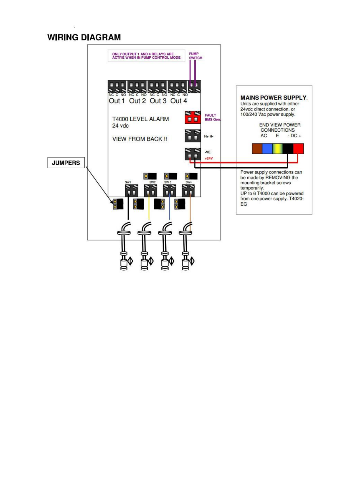
PSU Wiring .................................................................................................................................... 4
Product Description ............................................................................................................................. 5
Applications Include.......................................................................................................................... 5
Medium Controller can be used in.................................................................................................... 5
Technical Features................................................................................................................................ 5
T4000 –240PR/240AL....................................................................................................................... 5
T4000 - 24PR/24AL ........................................................................................................................... 5
T4000-12ALSP................................................................................................................................... 5
Description of Operation ..................................................................................................................... 6
Connection Settings ............................................................................................................................. 6
Inputs - Each of the 4 inputs can be set to........................................................................................ 6
Siren and BMS Outputs..................................................................................................................... 7
Alarm Mute....................................................................................................................................... 7
Test Mode......................................................................................................................................... 7
Pump Control Mode............................................................................................................................. 8
T4000 -T5020 Pump controller........................................................................................................... 10
T4000 Wiring Diagram Setting for Day Tank Control......................................................................... 11
T4000 Wiring Diagram Setting for WASTE Tank Control ................................................................... 12
T4000-12ALSP..................................................................................................................................... 13
FAQS................................................................................................................................................... 14

Page 3of 14
Introduction
The Purpose of this document is to outline the installation and operational procedures and the
operation of the T4000 Alarm Monitor and Controller series, the different variants are listed below.
T4000 - 24PR Pump Controller unit,24vdc powered.
T4000 - 24AL 4 Channel Alarm unit,24vdc powered.
T4000 –240PR Pump Controller unit 240vac powered
T4000 –240AL 4 Channel Alarm unit,240vac powered.
T4000-12ALSP 4 Channel Alarm, with Solar power and battery.
Safety Warnings
To avoid injury please read this manual carefully before installation. Failure to do so could result in injury or
failure of the equipment, this will invalidate any warranties given.
Warning
Installation
Mains Voltage –There are exposed electrical conductors inside this appliance of 240vac and
24vdc. This appliance must be installed and serviced by a competent electrical technician to
the current requirements of BS761 and IEEE recommendations. Before servicing this
appliance, normal safe isolation procedures should be implemented.
It is recommended that suitable circuit protection is installed and should include as a
minimum a suitable earth, overcurrent protection, and a residual current protection at
30mA, ideally on its own circuit, but always in accordance with BS7671 and applicable
regulations.
Do not touch any connection terminals while energised.
Do not attempt to service this item when wet, or in high humidity environment.
If the housing of the T4000 becomes damaged, you must shut down and securely isolate this
appliance immediately.
Included Components
T4000 Control Unit
Installation & Operation Manual
Required Components Not Included
Up to 4 x Float Switches or GXX Series Rigid Float Switches
OLE Gauge with Relays

Page 4of 14
Installation Instructions
Mounting Holes
There are 4 mounting holes in the base of the unit, these are located behind the front panel screws
See Figure 1 the distance between mounting holes is 110mm wide X 160mm high.
PSU Wiring
The T4000 has the option of coming with a 240vac to 24vdc PSU as shown below in Figure 1, if a PSU
is supplied then 240vac should be wired into the LNE terminals, the output of the PSU is 24vdc and
the +- terminals should be wired to the +- terminals of the T4000 as shown in Figure 2.
Figure 1

Page 5of 14
Product Description
The T4000 Alarm / Control unit has 4 digital inputs, this alarm monitor can be operated as a
standalone unit, it can also be setup as a Day Tank Pump Controller or sump Controller.
Applications Include
•Up to 4 x Tank Level Switches: LL, L, H, HH
•3 x Tank Level and 1 x Bund: Bund, LL, L, H
•2 x Level, 1 x Bund, 1 x Water: Bund, Water, L, H
•Secondary High - Level Alarm when combined with T5020 Automatic Pump Control
with fail safe.
•Day Tank Level control
Medium Controller can be used in
The T4000 can be used in applications using Diesel, Biodiesel, Gas Oil and AdBlue.
Technical Features
T4000 –240PR/240AL
Enclosure Size
125 x 175 x 75
Cable Gland Size
2 x m16, 1 x m20
Operating Temperature
0-60°C
I.P. protection degree
IP 65
Nominal Voltage
240Vac
Frequency
50/60Hz
Relay Max Contact Voltage AC
240vac
Relay Max Contact Voltage DC
24vdc
Relay Max Current
10Amps
Nett Weight
0.6kg
T4000 - 24PR/24AL
Enclosure Size
125 x 175 x 75
Cable Gland Size
2 x m16, 1 x m20
Operating Temperature
0-60°C
I.P. protection degree
IP 65
Nominal Voltage
24vdc
Relay Max Contact Voltage AC
240vac
Relay Max Contact Voltage DC
24dc
Relay Max Current
10Amps
Nett Weight
0.6kg
T4000-12ALSP
Enclosure Size
125 x 175 x 75
Cable Gland Size
2 x m16, 1 x m20
Operating Temperature
0-60°C
I.P. protection degree
IP 65
Solar Panel
Nominal Voltage (VMP)17.5V, Nominal Current
0.58A
Solar Panel
Nominal Power 10W
Nominal Voltage
12vdc
Relay Max Contact Voltage AC
NO=10Amps 250vac / NC=6amps 250vac
Relay Max Current
10Amps
Nett Weight
2.9kg

Page 6of 14
Description of Operation
•The T4000 Display panel provides a highly visible and reliable level indication.
•The illumination of one or more lights provide an indication of the power status.
•When lights are Green there is No Alarm.
•When an alarm condition occurs, the LED will Flash RED.
•When LED’s Flash RED and the Alarm/Mute button is pressed the Lights will change to
a fixed RED.
•When the T4000 is out of Alarm the LED will revert to Green.
•Multiple Alarms can be acknowledged at any time.
•During Pump On mode, LED’s are Orange.
•The BMS volt free output changes when any of the alarms are flashing Red or a solid
Red.
•The P and A jumper can be set so the T4000 can be used as a Pump controller or as an
Alarm.
•When in Pump control mode the Relay outputs 2 and 3 are not operational.
•When input 4 is in Pump control this also shuts down the Pump Circuit Fail Safe.
Connection Settings
•Float switches provided by OLE are Normally Closed (NC) When in the Down position.
•The T4000 inputs can be switched from NC to NO as required using the 2 jumpers on
each circuit. See Wiring diagram Figure 2.
•The 01 jumper can be removed to disable the alarm circuit. (No LED)
•The P and A jumper are to select if the system is to be used as a Pump controller or as
an Alarm.
•H+ H- is for an Audible Alarm that will activate when a Flashing RED LED condition is
present. (This is the supply voltage 24vdc)
•
Inputs - Each of the 4 inputs can be set to
•Not Used
•Normally Open (NO)
•Normally Closed (NC)
It is recommended NC is used as this provides a Fail-Safe input.

Page 7of 14
Siren and BMS Outputs
•Local Alarm / Siren connections Sounds when the LED Flashes and
Stops sounding when the alarm is acknowledged.
•BMS Remote connection is an output volt free passive contact that is normally closed,
this connection ‘OPENS ‘when an alarm is detected and the associated LED flashes,
The contact remains open even after the alarm has been acknowledged and will only
close when the LED’s are Green and in the safe operation mode.
This ensures BMS systems and similar control monitors can see when they are made
safe and not simply acknowledged locally.
Alarm Mute
•The T4000 has the capability of muting the audible alarm without deactivating
The remote output by simply pushing the ALARM/MUTE button, the sounder will be
Muted until the button is depressed.
Test Mode
•The T4000 has the capability of checking the audible alarm without activating
The remote output by simply pushing the ALARM/TEST button, the sounder will
Alarm as long until the test button is depressed.

Page 8of 14
Pump Control Mode
The T4000 can easily be configured to make it a pump controller by changing the position of
the jumpers as shown in Figure 2.
•When control input 2 is triggered, this latches the pump control relay on.
•When control input 3 is triggered, this unlatches the pump control relay.
•As a failsafe if input 4 is triggered the audible alarm will sound and the pump control
relay will open circuit.

Page 9of 14
Figure 2

Page 10 of 14
T4000 -T5020 Pump controller
You can configure a T5020 with a R5 relay board in conjunction with a T4000 as shown in Figure 3 to
provide a visual indication of the tank level in Litres, when used in this mode no float switches are
required.
Figure 3

Page 11 of 14
Power Supply
Units are supplied with either 24vdc direct connection,
or 100/240 Vac power supply.
Power supply connection can be made by removing the
removing the mounting bracket screws temporarily
nc/c/no
nc/c/no
nc/c/no
nc/c/no
Pump/
Switch
Out 1 Out 2 Out 3 Out 4
Fault
BMS
Gen.
H +
H -
+
-
SW1 SW2 SW3 SW4
T4000 Wiring Diagram Setting for Day Tank
Control
HH
blue
L
yellow
LL
White
H
purple
Connection Settings.
1/ Float switches from OLE are closed (NC), when they are in
the DOWN position.
2/ The T4000 inputs can be switched from NC to NO as
required using the 2 jumpers on each circuit.
3/ The 0/1 jumper can be removed to disable the Alarm
circuit. (No LED)
4/ The P and A jumper are for when the system is being used
as a Pump controller or as an Alarm.
5/ H+ H- is for an Audible Alarm that will activate when
Flashing RED condition is present. (This is the supply voltage
so 24vdc)
•Operation:
1/ When lights are GREEN = No Alarm
2/ When Lights Flash RED = Alarm / problem.
(ORANGE = PUMP ON)
3/ When the Acko button is pressed the Lights changed to
fixed RED This Auto resets when Alarm condition is removed.
4/ The BMS output (MC) changes condition (Volt Free) when
any of the alarms are flashing red or solid red.
5/ The P and A jumper are for when the system is
being used as a Pump controller or as an Alarm.
6/ When in Pump Control mode, Relay OUTPUTS 2 and 3 are
NOT operational
7/ When Input 4 is in “P” (Pump Control) this also SHUTS
DOWN the PUMP CIRCUIT FAIL SAFE
RELAYS RATED AT 240 VAC 10 AMPS
Wiring Diagram for pump
Control to fill a tank
O/1
O/1
O/1
O.L.E.
O/1
P/A
P/A
P/A
Note Jumper Positions

Page 12 of 14
Power Supply
Units are supplied with either 24vdc direct connection,
or 100/240 Vac power supply.
Power supply connection can be made by removing the
removing the mounting bracket screws temporarily
nc/c/no
nc/c/no
nc/c/no
nc/c/no
Pump/
Switch
Out 1 Out 2 Out 3 Out 4
Fault
BMS
Gen.
H +
H -
+
-
SW1 SW2 SW3 SW4
T4000 Wiring Diagram Setting for WASTE Tank
Control
HH
blue
L
yellow
LL
White
H
purple
Connection Settings.
1/ Float switches from OLE are closed (NC), when they are in
the DOWN position.
2/ The T4000 inputs can be switched from NC to NO as
required using the 2 jumpers on each circuit.
3/ The 0/1 jumper can be removed to disable the Alarm
circuit. (No LED)
4/ The P and A jumper are for when the system is being used
as a Pump controller or as an Alarm.
5/ H+ H- is for an Audible Alarm that will activate when
Flashing RED condition is present. (This is the supply voltage
so 24vdc)
•Operation:
1/ When lights are GREEN = No Alarm
2/ When Lights Flash RED = Alarm / problem.
(ORANGE = PUMP ON)
3/ When the Acko button is pressed the Lights changed to
fixed RED This Auto resets when Alarm condition is removed.
4/ The BMS output (MC) changes condition (Volt Free) when
any of the alarms are flashing red or solid red.
5/ The P and A jumper are for when the system is
being used as a Pump controller or as an Alarm.
6/ When in Pump Control mode, Relay OUTPUTS 2 and 3 are
NOT operational
7/ When Input 4 is in “P” (Pump Control) this also SHUTS
DOWN the PUMP CIRCUIT FAIL SAFE AVOID RUN DRY
RELAYS RATED AT 240 VAC 10 AMPS
Wiring Diagram for pump
Control to Empty a tank
O/1
O/1
O/1
O.L.E.
O/1
P/A
P/A
P/A
Note Jumper Positions
PUMP ON
PUMP OFF

Page 13 of 14
T4000-12ALSP
The T4000-12ALSP can be used in remote areas where there may not be any power, the unit is powered
By a TXX-12VPS-T which is a 12vdc lead acid battery unit which is continuously being charged by a solar panel,
power to the T4000 is initiated when the button on the front of the unit is pressed which then keeps the
power to the T4000 for a predetermined programmed time.
Please see the TXX-12VPS-T manual for full operational details.
T4000-12ALSP unit wired to a T4000

Page 14 of 14
FAQS
Q: Can the T4000 be used to control a Tank as well as emptying one.
A: Yes, the T4000 can be set to be used either way round and has an emergency automatic shut
down when the High level is reached on tank filling applications.
Q: Can any type of level switch be used on the T4000.
A: Yes, If the switches are “simple apparatus” meaning reed switch or similar. (Not capacitive or
resistance type)
Q: Can the T4000 Pump directly.
A: The T4000 can switch up to 10Amps at 250V, nothing with a greater current draw and working
voltage above these values should be switched, if the circuit load is more than the allowed a
separate contactor should be used in conjunction with the T4000.
Table of contents
Popular Security System manuals by other brands

Pentatech
Pentatech DG6 instruction manual

Tyco
Tyco MP-902 PG2 installation instructions

ELRO
ELRO CBFS58R-01 instruction manual

Alderon Industries
Alderon Industries Versa'larm 4X Operation, maintenance and installation manual

INTERVOX
INTERVOX Residencia 3 installation manual

Risco
Risco Agility 3 Installer manual