Oakdale F35 Joint Strike Fighter User manual

P/N 2060G, Rev C
F35 Joint Strike Fighter
Assembly Instructions
For .18-.25 Glow Ducted Fan Units

Oakdale Aircraft F35 Construction
Page 2
www.oakdaleaircraft.com
PRECAUTIONS:
This aircraft is not a toy. This model has been designed using state of the art miniature
ducted fan technology. For your safety and the safety of others, please observe all
product safety warnings for this kit as well as all accessories included. Also, please
follow all field safety rules.
This plane is capable of high speeds. If you are uncertain of your ability or have never
flown a radio controlled model aircraft before, please seek the help of an expert. Oakdale
Aircraft strongly recommends you be a member of the AMA (Academy of Model
Aeronautics).
Read through this construction manual in it’s entirety before starting so you have a
thorough understanding of the building process.
Complete all instructions in the manual including assembly, radio and engine installation,
pre-flight, and flying. Every attempt has been made to include guidance through all
phases of this kit and by doing so, you will enjoy many flights with this model.
SPECIFICATIONS:
Length: 40” (1016mm)
Wing Span: 30” (762mm)
Power: .18-.26 Ducted Fan Unit (Toki .18, Kress RK720, etc…)
Control Functions:
Throttle, Taileron, Nose Wheel Steering, Retracts
Radio:
Minimum 4 channel with elevon mixing or V-Tail mixer
Mini servos (tailerons)
Micro servos (Nose steering, retract valve, throttle)
Control Surface Throws:
Taileron Elevator:1/2” (12.7mm)high, 3/8” (9.5mm) low
Taileron Aileron: 3/8” (9.5mm), 1/4” (6.5mm) low
Exponential: -40%
Nose Wheel Steering: 10°
(adjust these as necessary after first flights)
Weight:
2.5-4lb
CG:
1/8”-1/4” aft of the forward edge of the main hatch

Oakdale Aircraft F35 Construction
Page 3
www.oakdaleaircraft.com
BILL OF MATERIALS:
Part
Number Qty Description
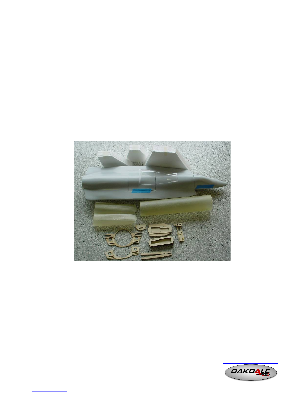
2000 1 F35 Molded Fuselage
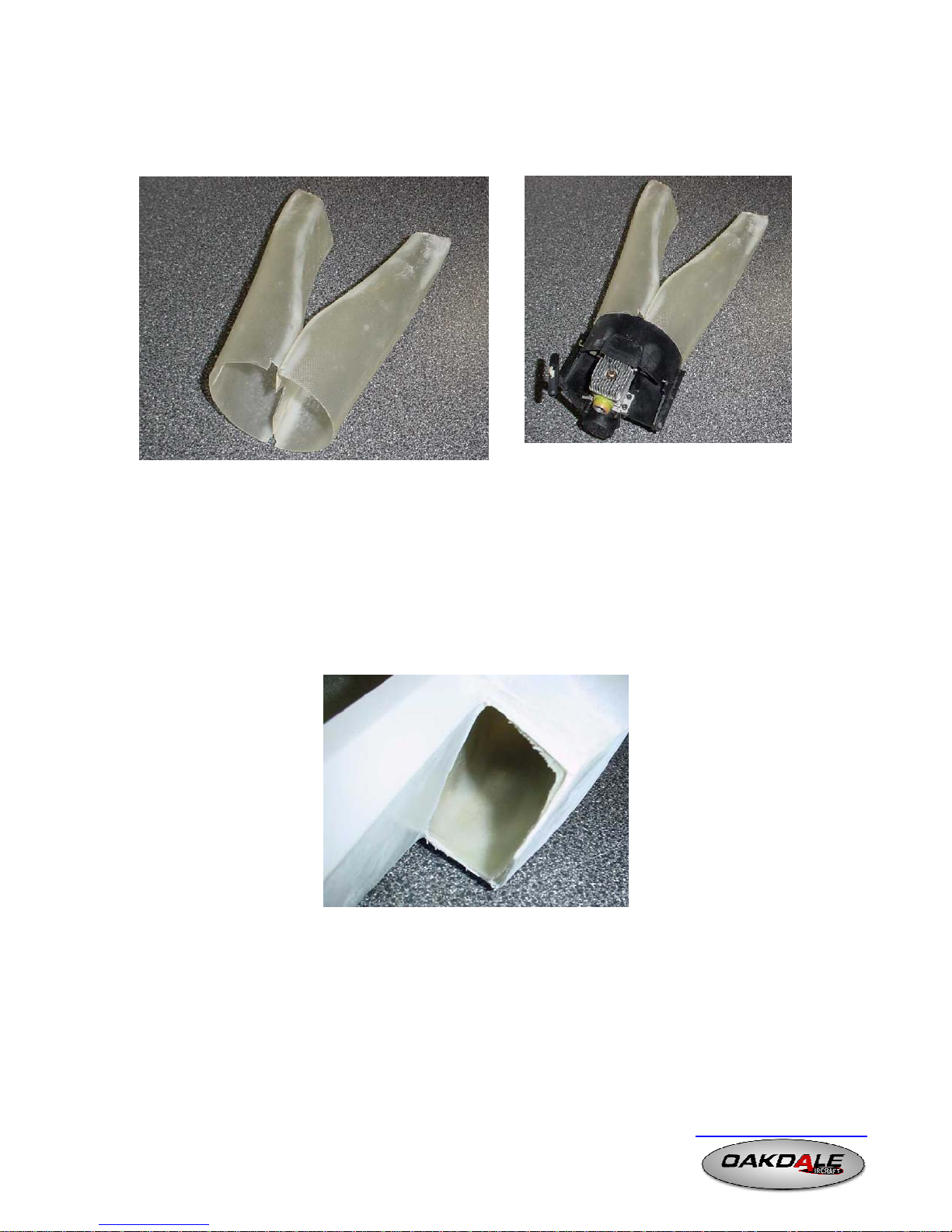
2001 1 Intake Ducting
2002 1 Exhaust Ducting
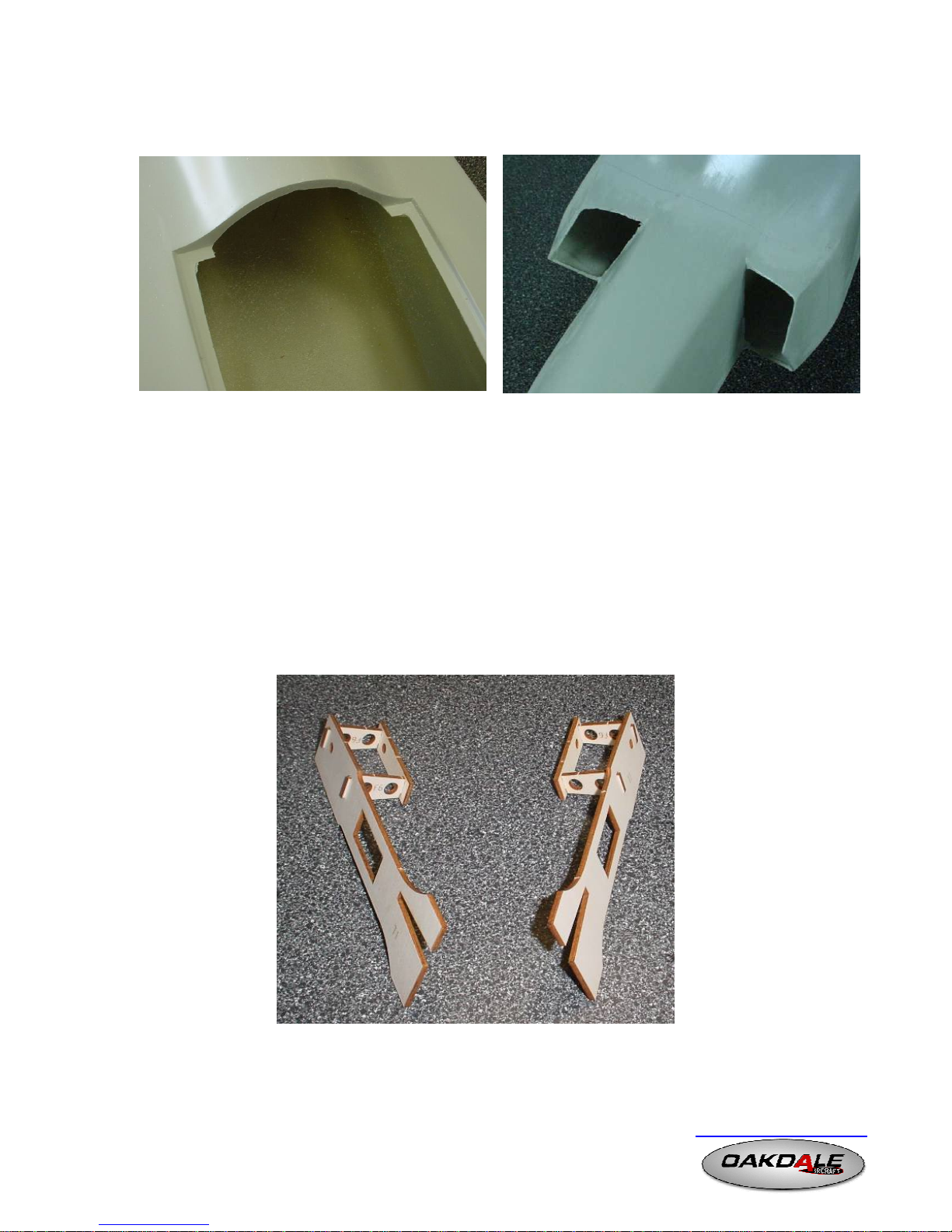
2005 1 Laser Cut Ply Set
2006 1 Laser Cut Formers
2010L 1 Foam Core, Wing, Left
2010R 1 Foam Core, Wing, Right
2011 1 Foam Core, Taileron
2012 1 Foam Core, Fin
2015 1 Vacuum Formed Clear Canopy
Hardware Pack
2021 1 Hinges (Robart)
2022 1 Wire, Main/Nose Gear-1/8"x36" (K&S)
2023 2 Main Wheels, 1-1/2” (Great Planes/Dubro)
2024 1 Nose Wheels, 1-1/4” (Great Planes/Dubro)
2025 1 Wheel Collar Set-1/8" (Dubro)
2026 8 ¼” x 1/8” Rare Earth Magnets
2027 2 Nose Wheel Steering Cable (ft) (Oakdale)
2029 4 6-32 wood screws (fan mounting) (Oakdale)
2030 1 Main Gear Straps (1/8") (Dubro)
2031 2 Pushrod (w/ clevis) (Dubro)
Balsa Pack
2040 10 1/16" x 3" x 36" Balsa Sheet
2041 1 1/8" x 3/8" x 36" Balsa Stick
2042 2 3/8" x 3/8" x 36" Balsa Stick
2043 1 1/2" x 1/2" x 36" Balsa Stick
2045 1 3/16” x 6” Spruce Dowel
2046 1 ½” x ½” x 12” Hardwood
Optional Glow Pack
2050 2 Fuel Tanks (Sullivan Oval)
2051 3 Fuel Tubing (ft) (Dubro)
2052 2 T-Fitting (Oakdale)
2053 1 Pushrod (w/ clevis) (Dubro)
2060G 1 F35 Instruction Manual
Note: Italic part numbers are included in the standard kit only

Oakdale Aircraft F35 Construction
Page 4
www.oakdaleaircraft.com
REQUIRED TO COMPLETE:
Components:
Ducted Fan Unit
Radio Unit (4 Channel with Elevon Mixing or separate V-Tail Mixer
Accessories:
(3) Servo Wire Extensions (2 24”, 1 18”)
V-Tail Electronic Mixer (if building with tailerons and do not have mixing capabilities)
Monokote or other Mylar covering
Paint
Tools:
Adhesive
5 minute epoxy
30 minute epoxy
Cyanoacrylate
Silicone Adhesive
Gorilla Glue
Sandpaper-200, 220, 300, 400, 600 grit
Sanding Block
Masking Tape
File
Razor blade or knife
Rotary tool (i.e. Dremel)
Straight Edge
3/16" Drill Bit + Drill
1/16” Drill Bit
Incidence Gauge (Robart or Great Planes)
For Fiberglassing:
Epoxy resin (West Systems or AeroPoxy Recommended)
Microballons type resin thickener
Squeegee/Brushes
Disposable Containers
Mixing sticks
Acetone (for clean up)
Scissors

Oakdale Aircraft F35 Construction
Page 5
www.oakdaleaircraft.com
Assembly Instructions for the F35 Joint Strike Fighter
Note: During assembly of this model, you must at all times strive to keep the weight as
low as possible. This kit has been designed to build easily and fly the same. Excess
balsa, glue and any other components will only add to the weight and decrease the
performance.
This kit is built using taileron control, therefore a computer radio is required. If you do
not have a computer radio, an electronic mixing V-Tail unit can be used. Let’s get
started:
FUSELAGE:
Identify all the laser cut parts and using a sanding block, remove any burrs around each
part.
Remove the hatch and canopy from the fuselage.
Using warm water and soap, thoroughly wash the entire fuselage, hatch and canopy,
both inside and out. Also wash the intake and exhaust ducting. Let dry completely. This
will remove any remnants of mold release wax that may still be on the parts.
Using a rotary tool, cut the openings for the intake and exhaust ducting. Leave approx
1/16-1/8” lip around the face. This will be sanded and smoothed out after the intake is
installed.

Oakdale Aircraft F35 Construction
Page 6
www.oakdaleaircraft.com
Using a rotary tool, remove the two face’s in the engine hatch compartment and engine
hatch to allow clearance for the ducting. Leave approx 1/8-1/4” lip around the edge.
TAILERON SERVO MOUNTS:
Locate the taileron servo mount formers (2 F6’s, T1, T2).
Trial fit together T1 and T2 to the spacer F6’s per the image below.
Glue the sub assembly together using 5 minute epoxy, keeping assembly square
Repeat for the opposite subassembly ensuring both subassemblies are mirrors of each
other
Mount the taileron servos per the image below (mini servo’s are recommended).

Oakdale Aircraft F35 Construction
Page 7
www.oakdaleaircraft.com
Slide the taileron sub assembly into the fuselage until snug.
Glue in place using epoxy.
INTAKE DUCTING, ENGINE MOUNTS AND MAIN GEAR MOUNTS:
Locate the following laser cut components:
F3, F4, EM, MGM (or FMGM), F3-S, F4-S, and F4-S2
Glue F4-S and F4-S2 to former F4. Glue F3-S to former F3.
Using 5 minute epoxy, double up the Engine Mounts (EM). Trial fit the EM’s into the
notches in F3 and F4 to verify the fit. Sand if necessary to obtain a snug, but not tight fit.
Trial fit together F3, F4, both EM’s and both MGM’s (do not glue together the MGM’s
at this time). Disassemble when satisfied with the fit.

Oakdale Aircraft F35 Construction
Page 8
www.oakdaleaircraft.com
Trial fit the intake ducting into the fuselage ensuring each part is positioned as far
forward as possible.
If required, use a dremel rotary tool with a grinding wheel or a file to carefully remove
any of the corner filler inside the fuselage so the intake slides in place to the end.
With the intake ducting in place, trial fit former F3 in place supporting the back end of
the ducting. Former F3 should be located flush with the end of the ductings.

Oakdale Aircraft F35 Construction
Page 9
www.oakdaleaircraft.com
Trial fit former F4 in place with the Engine Mounts (EM) in place. Former F4 should
be past the rearmost panel line of the main gear doors. If it is not, adjust the intakes and
former F3.
With F4 temporarily in place, cut an opening in the side of the fuselage for the wing
spar to pass through and connect to F4.
Retracts, Fixed Gear, or No Gear
If installing retracts, double up the Main Gear Mounts (MGM) using 5 minute epoxy.
Temporarily mount the retract units to verify the mount and method of retraction.
If you are installing fixed gear, use the FMGM’s instead of the MGM’s.
If you are not installing gear at all (for bungee launch), do not use either the MGM or
FMGM. You will install a bungee plate at a later time.
Intake Preparation
Using a hobby knife or razor saw, remove approx 1/4" from the inside edge of each
intake to provide an overlap over the fan unit. Also, remove material where the nose
cone of the fan unit will reside.

Oakdale Aircraft F35 Construction
Page 10
www.oakdaleaircraft.com
Tape the two inlets together along the inside edge and temporarily fit it to the fan
shroud. Trim the inlets as necessary to ensure a proper fit.
Toki .18 Fan unit shown
When satisfied with the fit between all of the intake and former components, prepare to
glue them in place.
Using 30 minute epoxy or epoxy resin (recommended), produce a mixture with a
microballoon filler until it is of a thick, pasty consistency.
Apply the mixture to the inlets of the fuselage where the intakes will be glued.
Slide the intakes in place and ensure they are positioned as far forward as possible and
are glued all the way around. Remove any excess resin before it cures. Don’t worry
about shaping the intakes right now. This will be completed after the resin has cured.
Slide in place former F3 to support the intakes while they cure. Using medium CA,
temporarily tack the intake to the former to ensure proper positioning.
When the intake has cured, glue former F3 to the fuselage and let cure.

Oakdale Aircraft F35 Construction
Page 11
www.oakdaleaircraft.com
Follow up with a scrap piece of fiberglass cloth or 1/64” ply to cover the intake joints
in the inside of the fuselage.
When F3 has cured install former F4, and MGM’s. The EM’s can be positioned to
help align the structure while the glue cures, but do not glue at this time.
NOSE GEAR MOUNT:
Before you begin, chose which method of gear you will be installing: Retracts, Fixed Gear, or Bungee
Retracts:
Locate the nose gear mount formers (F1, F2, NGM, & NGM-top).
Using 5 minute epoxy, double up the Nose Gear Mount (NGM) and NGM-Top.
Trial fit together F1 and F2 to the NGM sub assembly.

Oakdale Aircraft F35 Construction
Page 12
www.oakdaleaircraft.com
When satisfied with the fit, disassembly the parts and prepare to mount the retracts.
Trial fit your retract unit to the NGM to ensure the location and movement of the gear.
Note: The retract unit is shown on top of the
NGM for clarity. Actual gear should be
mounted on bottom of mount.
Glue in former F2, lining it up with where the intake joins the fuselage at the inside.
For reference, the former should be at or behind the gear door line marked on the outside
of the fuselage.
Glue F1 and the NGM to F2.
Using a razor saw, or hobby knife, cut out the nose gear door along the inscribed lines
on the outside of the fuselage. Save the door piece of you wish to install the gear doors.
Test fit the NGM sub assembly to the inside of the fuse, centering over the gear door
opening.
When satisfied with the location, glue in place using 30 minute epoxy.
Note: Following up with a microballoon/epoxy fillet is strongly recommended due to this area being
subjected to high loading and impact. Apply the filler around formers F1 and F2 as well as along the
NGM and the fuselage wall.

Oakdale Aircraft F35 Construction
Page 13
www.oakdaleaircraft.com
Fixed Gear:
Follow the same assembly procedure as the Retracts, but use Fixed Nose Gear Mounts
(FNGM) in place of the NGM.
The gear door can be removed or left in place.
No Gear/Bungee Launch:
On the bottom of the fuselage, mark a position 9” back from the nose. This will be the
bungee hook location.
Trim the FNGM so a piece fits inside the bottom of the fuse, centered over the mark
made on the outside. Glue in place using 30 minute epoxy.
Install your Bungee hook in the FNGM after the plate has cured.
CANOPY, CANOPY HATCH AND MAIN HATCH:
You will be using Rare Earth Magnets to hold the hatches in place, which are much stronger than
normal magnets. Before you begin, make sure you know the polarity of each side of the magnets.

Oakdale Aircraft F35 Construction
Page 14
www.oakdaleaircraft.com
Canopy:
If you are installing the vacuum formed clear canopy, cut out the canopy per the
molded in framing lines.
Canopy Hatch:
Locate the rare earth magnets that will be used for the hatches.
Snap two of them together and then using coarse grit sandpaper, roughen up the outer
surfaces of the each magnet. Do this for 4 pairs of magnets. Separate two pairs of
magnets.
Mark the location on the fuselage of where the two canopy magnets will be glued and
remove material using a drill or Dremel.
Using scrap balsa, build up a platform for the magnet to be glued to so that the top (the
un-roughen surface) sits flat with the canopy hatch flange.
Using 30 minute epoxy, glue each magnet in place
When the epoxy has fully cured, mount the canopy hatch in place and mark where the
canopy magnets will be glued.
Using epoxy, glue the magnet in place on the canopy hatch so the magnets sit flush
with the bottom surface.
Let fully cure before connecting the canopy hatch to the fuselage.

Oakdale Aircraft F35 Construction
Page 15
www.oakdaleaircraft.com
Trial fit the canopy to the fuselage to ensure it snaps in place.
Using the 3/16” dowel or small piece of ply, glue into the nose of the canopy a hatch to
provide a lock at the front.
Drill a receiving hole into the fuselage to accept the canopy tab.
When satisfied with the mount, trim the vacuum formed canopy to fit inside the
canopy hatch.
Using epoxy or canopy glue, glue the clear canopy in place. Do not use CA as the
fumes will leave a white residue over the canopy which will be difficult to remove.
TIP:
To obtain a perfectly matching hatch with no visible joint line,
follow these simple steps:
a.) Apply a mixture of epoxy resin and microballons to the
perimeter of the canopy where it seats on the fuselage.
b.) Lay a piece of waxed paper over the microballons bead
c.) Install the canopy pushing it down against the fuselage
until it is seated properly and the microballons mixture has
squeezed out the joint.
d.) Let fully cure.
e.) Using 100 grit sandpaper, carefully sand down the epoxy
bead until the joint is smooth (don’t worry about the waxed
paper, it’ll be sanded down as well).
f.) Remove the canopy and the paper.
g.) Repeat by applying a bead of epoxy with microballons filler to the fuselage. Place the waxed paper
over the top of it. Install the canopy and squeeze out the excess. Let cure and sand.
You should now have a perfectly matching canopy joint. This technique can also be applied to the main
hatch.
Main Hatch:
Following the same procedure as the canopy, glue in place two magnets to the hatch
and two to the fuselage.

Oakdale Aircraft F35 Construction
Page 16
www.oakdaleaircraft.com
Using some scrap ply, glue to the hatch two tongues on the opposite side of the
magnets.
Mark the location of the tongues on the fuselage hatch flange and cut out.
When the epoxy has fully cured attach the hatch in place to ensure a proper fit.
WING, TAILERON, FIN CONSTRUCTION:
For the construction of the wings, tailerons and fins, you will need to sheet the foam core
with balsa skins. There are numerous methods to do this. The following method is just
one example.
Open the foam wing core from it’s cradle and inspect the overall surface and shape.
Ensure there are no defects. If there are any dents or defects, fill them with lightweight
model filler and sand smooth.
Using a sanding block with 300+ grit sandpaper, lightly sand the foam cores of any
“fuzz” or “hair”.
Begin by doubling up the wing spars using epoxy.

Oakdale Aircraft F35 Construction
Page 17
www.oakdaleaircraft.com
Measure back 5 5/8” from the leading edge of the wing and mark the foam core.
Using a 90º square, mark the core 5 1/4” in.
Using a razor knife or saw, remove the foam to fit the wing spar, using the marked line
as a centerline. Do not remove excess foam. Take your time. You want a snug fit
between the foam and the spar.
Trial fit the core onto the wing spar.
Repeat for the opposite core.
Sheeting:
For each side of the wing, 4 sheets will be necessary. Butt the sheets up against each
other and use masking tape to hold together. Tack in a few places using CA. (Note:
The grain direction should be parallel to the spar or the leading edge).
Position the wing cores on the sheets and trace the outline, making them slightly larger
(1/4”) all the way around.

Oakdale Aircraft F35 Construction
Page 18
www.oakdaleaircraft.com
Cut out the sheets.
Repeat for the opposite surface sheet. Make sure that each sheet has the tape on the
"outside" surface.
Before mixing up your glue test fit the sheets and the cores in the cradles to make sure
you have everything set correctly.
Locate 10-20lb of weight and have it near your work area before you mix anything.
To glue the sheets to the wing cores use a slow cure epoxy resin or adhesive such as
Gorilla Glue.
Lay the bottom sheeting on a work table, placing the taped surface down.
Use a small squeegee or brush to spread a thin coat of glue over all the sheets.
The use of waxed paper between the cradle and balsa sheets will help keep the parts from sticking
together when cured.
Place the bottom sheeting of the wing core down into the cradle with the glue surface
up.
Place the foam core on the glue surface of the sheeting.
Repeat for the top sheeting then place on top of the core.
Place the top piece of the cradle on the top of the wing and center everything.
Place the cradle on a flat surface and put a flat board on top of it. Place 10-20lbs of
weight on top of the board evenly distributed and allow to dry for 24 hours. Make sure
you use a flat surface and a flat board when sheeting the wings to prevent warps or
twisting.

Oakdale Aircraft F35 Construction
Page 19
www.oakdaleaircraft.com
Note: There is washout built into the wing, so it may appear slightly twisted.
After the wings have dried for 24 hours, remove them from the cradle and inspect.
Cut the sheeting at the leading and trailing edge of the foam and flush with the edges
being careful not to cut into the foam.
Use a ½” square balsa stick and epoxy for the leading edge and tip block.
Once dry, sand the ends flush and shape the leading edge and tip block to match the
top and bottom of the wing profile.
Sand the trailing edges leaving a thickness of approximately 1/16”.
Sand the entire wing.
Wipe the entire surface with a damp cloth, removing all the dust.

Oakdale Aircraft F35 Construction
Page 20
www.oakdaleaircraft.com
FIN CONSTRUCTION:
Using the method described in the wing construction section, sheet the fins.
Attach the leading edge and the tip blocks using 3/8” square balsa.
Apply a 3/8" wide x 1/8” thick balsa strip to the base of the fin. Sand smooth to match
the contour of the fin.
TAILERON CONSTRUCTION:
Using the method described in the wing construction section, sheet the tailerons.
Attach the leading edge and the tip blocks using 3/8” square balsa.
Mark on the top of the taileron, the location of the cutout leaving a 3” wide extension,
2.5” deep. (Edges A and B are parallel. Edges B and D are perpendicular.)
Cut a slot into the 2.5” wide face A for the ½” hardwood block (to be used for the
hinges).
Glue in using 30 minute epoxy.
Using 1/16” balsa sheet, face off the exposed foam and sand to match the contour of
the taileron.
Table of contents
Popular Toy manuals by other brands

Lionel
Lionel Scale GP9 Diesel Locomotive owner's manual

Mega Construx
Mega Construx Call of Duty FDY74 instructions

Canon
Canon Creative Park Paper Aquarium Clown Fish Assembly instructions

Mega Construx
Mega Construx Monster High DYC72 manual

Associated Electrics
Associated Electrics RC10TC6.2 Assembly manual

FunParts Xpress
FunParts Xpress Go-Kart Parts guide

Mattel
Mattel Hot Wheels Custom Motors R1237 instructions

Trix
Trix 182 Taurus Series manual

Fisher-Price
Fisher-Price THOMAS & FRIENSA TRACK MASTER instructions

REVELL
REVELL Messerschmitt Bf 109 F2/4 instruction manual

Mega Construx
Mega Construx HALO WARRIOR CNC84 quick start guide

Fisher-Price
Fisher-Price Pool Party C6317 manual