Oakley Sound Rack Power Supply Unit (RPSU) User manual

Oakley Sound Systems
Rack Power Supply Unit
(RPSU)
PCB Issue 1
User Manual
V1 0 1
Tony Allgood
Oakley Sound Systems
CARLISLE
United Kingdom
1

Introduction
This is the User Manual or issue 1 o the RPSU circuit board rom Oakley Sound. The
Oakley RPSU is a power supply unit designed to be used in conjunction with the Oakley rack
projects like the HVM and SE330. However, it may also be used with a Dizzy module as part
o a larger DIY project.
As well as giving details as to what the PSU board does, this document contains instructions
on how to wire up your board to your source o power, any external switches and the optional
power indicator. I will also give you some in ormation about suitable sources or your low
voltage AC power supply.
The Oakley PSU allows or various options in the installation. You can use the unit either in
ull wave recti ication mode or connection to tapped linelumps or twin trans ormer
secondaries, or in hal wave recti ication or single phase AC output wallwarts and linelumps.
I all this sounds very con using at the moment, do not worry, in this manual I will try to make
it clearer so that you make the right decision about what power source you will need.
I you are building the RPSU as a complete DIY project please also download the latest
Builder's Guide. This can be ound on the main RPSU webpage along with our very use ul
generic parts and construction guides.
2

Sa ety Warning
This supply has been designed to work with isolated low voltage AC inputs only. Connection
to any alternating current supply is done at your own risk. Low voltage is classi ied as being
less than 25V with respect to the ground potential. Voltages above this level can, and o ten
are, lethal to living creatures.
Oakley Sound Systems will not advise on building or modi ying this board to allow or direct
connection to the mains, or other high voltage sources, urther to what is provided in this
document. Please do not ask us or additional in ormation pertaining to direct mains
connections or using internally mounted trans ormers as we will not give it.
For safety and legal reasons we cannot recommend powering this board from any other
supply than low voltage AC output mains adapters
Oakley Sound Systems are not liable or any damages caused by the misuse o this product. It
is your responsibility to use this product sa ely. I you have any doubt about installing a sa e
power supply, then please do not attempt to do so.
3

The Oakley RPSU module
This power supply board will allow the conversion o a suitable low voltage alternating
current (AC) to be recti ied, smoothed and regulated. The module is designed to be itted to a
suitably large metal panel which unctions as a heatsink or the two regulator devices attached
to the RPSU circuit board. The metal panel should have adequate air low around it and it is
expected that it will be part o the metal enclosure your rack project is built into.
It is possible, i the RPSU is only powering a small amount o electronics, that the unit can be
used with either no heatsinks or just small clip-on types. However, it is up to the builder to
determine whether or not this is possible. I in operation the two power devices get too warm
to touch or more than ten seconds you will need additional heatsinking. I the RPSU is
powering just one HVM it will need heatsinking.
The voltage output o the power supply module is a split rail 15V supply. This means it
generates both +15V and -15V. That is, two power rails, one o a positive voltage, the other a
negative one. These voltages are measured with respect to a common ground which is
normally connected, via your house's wiring, to the earth that you stand on. The voltage
across both rails is 30V, with the common ground sitting exactly in the middle o this at 0V.
The output current capability is the maximum current you can draw out o the power supply.
The current taken rom the supply is determined by the amount and type o modules you are
connecting to the power supply. One HVM will draw around 80mA rom the +15V supply
and 80mA rom the -15V supply.
The Oakley RPSU eatures current limiting but only what is built into the two power devices.
Although this will probably stop your project rom bursting into lames it is not to be relied on
i the ault continues or a long period o time. The RPSU is itted with uses and the correct
choice o use will probably save your project in the event o a major breakdown.
I you are using a single phase 500mA (or 0.5A) AC wallwart* then the most current you can
take rom this power supply module is around 125mA rom each rail. This is enough to drive
one HVM. You may think that a 500mA power pack should be able to drive up to 250mA or
each rail. But simple arithmetic does not work when you are dealing with conversion rom AC
to DC. The various parts o the power supply require power to work and this reduces the
use ul power we can actually draw rom the supply. The rule o thumb is that the AC current
drawn is roughly 1.8 times that o the DC current drawn. This means we can take 278mA
rom both supplies, that is 139mA or each rail. To allow or some sa ety margin we drop this
down to 125mA per rail which allows or a 10% overhead. This is plenty enough or one
HVM but not much else.
Various companies make wallwarts* and linelumps** with a greater capacity than 500mA. I
you can get a 1A output one than this will be able to drive up to 250mA per rail. With any
single phase supply you will be using your RPSU in hal wave recti ication mode. Single phase
mains adapters are the most common and have only two wires coming rom them. They are
normally connected to the rack with a barrel type plug.
4

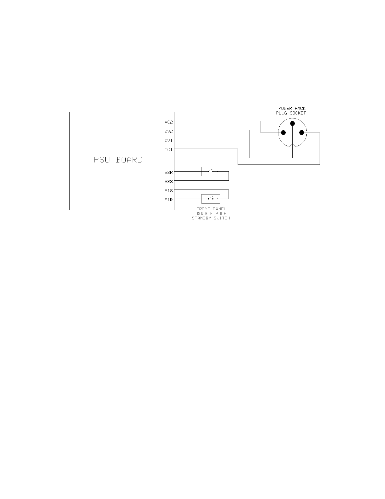
Some linelumps, like the Yamaha PA-20 and PA-30, use a split AC output or a centre tapped
AC output. This means it has three wires coming rom it and will use a di erent plug rom the
usual round barrel one you see on the single phase AC wallwarts. With a split AC output the
Oakley RPSU should be wired to work in ull wave recti ication mode.
The Yamaha PA-20 supply is rated to give an output voltage o 35Vac (with a centre tap) at a
load o 0.94A. Once recti ied and smoothed this means that a maximum current o 0.52A per
rail can be drawn rom the RPSU. This is plenty enough to drive the HVM and an SE330.
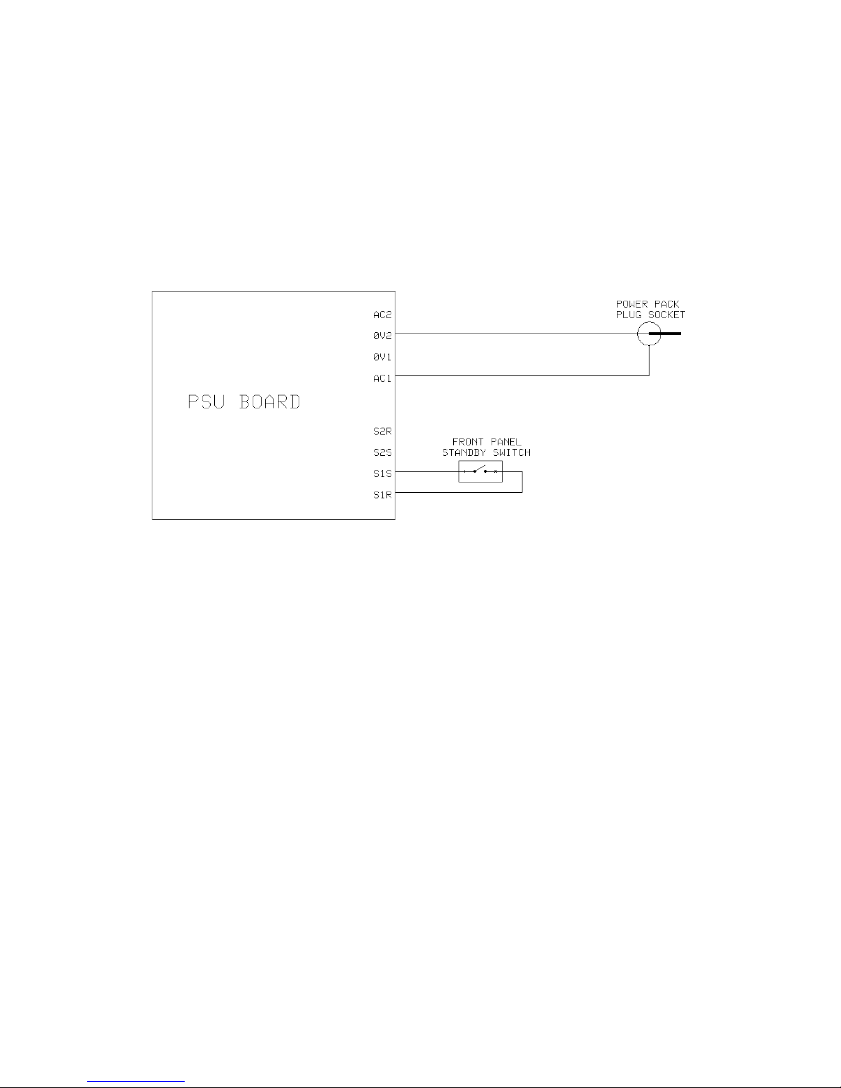
Two sets o screw terminal blocks are provided or connecting the low voltage AC power
source to the board and the optional power switch. I you are using a single phase wallwart to
power the RPSU module than you need only to use two terminals per terminal block.
The board has our mounting holes or stable placement onto your modular case. Care should
be taken so that the board's various board mounted components do not come into contact with
any part o the enclosure. One o the mounting holes, the top right hand one, is connected to
the ground point o the RPSU via a 'resistor', R5. In most situations R5 will be a low value
resistor but see later or more details on this.
The power supply has two integral use holders in case o a problem with the power supply
circuitry itsel . Two uses are needed i you are using ull wave recti ication, but only one, F2,
is required or hal wave recti ication. The use type should be a slow blow or anti-surge type.
The size is 20mm. It should be rated at between one and two times the maximum current o
your wallwart. Thus a 500mA AC output mains adapter should have a use that is rated
between 500mA and 1A, ideally 750mA. A 1A linelump should have a use that is between 1A
and 2A, ideally 1.5A.
There is one LED indicator or the AC input. This can be built onto the board, itted to the
ront panel or omitted altogether. Both the HVM and SE330 modules have power on
indicator LEDs. However, the RPSU's LED will light as soon as AC power is applied and not
just when the unit is switched on.
As we have seen the standard circuit provides two outputs, one at +15V and one at -15V.
Both output voltages can be inely adjusted with its own trimmer. Unlike some power supplies
the -15V rail will not track the +15V. The RPSU contains two separate, but complementary,
power supplies.
The output voltages are available rom two 3.96mm Molex KK or MTA headers.
* A wallwart is the vernacular term or a low voltage mains adapter that plugs directly into the
wall. These take the orm o a black plastic block that is shaped like an oversized mains plug.
It is called a wart simply because its appearance is somewhat uglier than a normal slimline
plug.
** A linelump does the same job as a wallwart but it generally can handle greater currents.
Because o its increased size it cannot be made so that it will sa ely it into a plug socket
directly. Thus the adapter sits in a black plastic box and connects to the wall via a cable and
traditional mains plug. It is there ore a black plastic lump connected to a line. The Yamaha
PA-20 and PA-30 are such linelumps.
5

The Power Supply to the Power Supply
The standard method o powering the unit is rom a low voltage tapped AC source. The sa est
available option is to use a ready made 'wallwart' or ‘line lump’ supply.
You can use any 15V or 18V AC output wallwart o linelump you can source. The current
capability o the mains adapter, sometimes incorrectly called the 'ampage', will determine the
maximum current draw o your PSU.
Maplin N57AT
This is a 500mA single phase AC output wallwart. It is a variable output type. This means it
has a little selector switch on the underside o the unit that allows you to change the output
voltage. You should select 15V or operation with the RPSU board. I do not recommend you
take more than 125mA per rail.
Because this is a single phase unit the Oakley PSU is wired in hal -wave recti ication mode.
You notice that only two wires come out o the wallwart and that you can select rom a
variety o output socket types. Simply chose the one you would like to use on your system
and buy the appropriate socket or it to go into. I tend to recommend the 2.5mm DC power
plug one since this is the most common type o power socket.
You should it use F2 only and it should be an anti-surge type and rated between 500mA and
1A.
Maplin N58AT
This is a 1A single phase unit. It has the potential to deliver up to 250mA per rail when the
Oakley PSU is used in hal wave recti ication mode.
6

Yamaha PA-20
This is a linelump supply and eatures a ixed 17.5-0-17.5 volt AC output at 0.94A maximum.
This means it gives us two AC outputs with a centre tap or mid point re erence voltage. So
unlike the single phase AC adapter output with two leads, this one has three. This means you
need to use the Oakley RPSU in ull wave recti ication mode.
The PA-20 is made or Yamaha products and they are available rom Yamaha spares
departments as well as many music shops, eg. Thomann. These are CE approved and connect
to the mains via your local mains connector. They will be di erent types depending on the
country you need them or. It comes with a handy three way plug at the low voltage end that
you can use with an appropriate socket. I you wish you can ditch their connector and use
your own. Maplin in the UK sell a suitable three way connector to it the Yamaha one
per ectly. Their part number is FM51F.
In the UK the line lump’s part number is V9812300 and the total cost is around £35 including
VAT and postage. I you are buying these direct rom Yamaha and, or some reason, are
asked why, the probably best thing is to say it is or a MG12/4 mixer.
Once recti ied, smoothed and regulated the Yamaha PA-20 can deliver up to 0.52A
continuously into both 15V rails.
You should it both uses and both should be anti-surge types and rated between 1A and 1.6A.
The European version of the PA-20. Other country's units are similar but will have the local mains
connector fitted.
I you have success ully used the Oakley PSU with any other types o power pack please do
let the community know via the Oakley Sound orum at www.mu wiggler.com
7

Linelumps and Wallwarts: Wiring Diagrams
Input wiring will depend on the type o wallwart or linelump you will be using.
Standard AC output wallwart
Single phase, two wire, wallwarts or linelumps need to use hal wave recti ication so the
Oakley PSU can generate both positive and negative supplies simultaneously. They only need
the terminal's AC1 and 0V2 wired to the power socket. AC2 and 0V1 are le t unused.
allwart with single phase AC output, eg. Maplin N57AT
The ront panel switch is a single pole single throw (SPST) switch which simply connects S1R
and S1S together when switched on. You can replace the switch with a simple wire link, but I
do recommend that a switch be itted so the socket doesn't have to take the ull surge current
when you insert it with the wallwart powered up.
I also recommend itting the AC indicator LED too. This is so you know the wallwart or
linelump is on. The AC indicator is designed to indicate the status o incoming power and is
not determined by the position o the standby switch.
The standby switch should not be used to turn the unit o permanently. This should be done
by either switching the adapter o at the mains socket, or by pulling the adapter's plug out o
the mains socket.
R5 should be itted and is a 47R, 1/4W resistor.
8

Centre tapped wallwarts and linelumps
Centre tapped linelumps like the Yamaha PA-20 will have three wires coming rom their
connector. It will have two AC outputs and one 0V. Take one o the AC outputs to terminal
AC1 and the other AC output to terminal AC2. It should not matter which AC output goes to
AC1 or AC2. The 0V should go to the 0V2 terminal. The 0V1 terminal is le t unused.
Figure 2. Linelump wiring with centre tapped output, eg. Yamaha PA-20
The ront panel switch is a double pole single throw (DPST) switch which connects S2R and
S2S together, and S1R and S1S together, when switched on. You can replace the switch with
two wire links, but I do recommend that a switch be itted so the socket doesn't have to take
the ull surge current when you insert it i the linelump is powered up.
I also recommend itting the AC indicator LED too. This is so you know the linelump is on.
The AC indicator is designed to indicate the status o incoming power and is not determined
by the position o the standby switch.
The standby switch should not be used to turn the unit o permanently. This should be done
by either switching the adapter o at the mains socket, or by pulling the adapter's plug out o
the mains socket.
R5 should be itted and is a 47R, 1/4W resistor.
9

Using an Internal Mains trans ormer
Be a raid, be very a raid...
Some o you old hands will laugh about the level o hysteria that surrounds direct mains
connection to DIY projects. However, this ear is more to do with our litigious society than
the real danger to the builder. Even so, I have had more than my air share o high voltage
shocks over the years and it is not something I would want any builder to have to experience.
It has been purely luck that has saved me in several o those cases.
So I will say again – do not attempt to build a mains trans ormer into your case, or any other
project, without realising that to do so carries a risk o death to either you, or to the person
who may inadvertently put their ingers into your hal built construction. Furthermore, it is up
to you as the builder o such an item to make sure, that once built, the item is sa e to use and
meets all current sa ety legislation.
This is not a complete set of instructions on how to fit a transformer into a piece of
electronic equipment This information is offered only as a guide and should not be
considered as your only source of information No further information, other than that
included here, will be provided by myself or Paul Darlow regarding the construction of
mains powered items
For powering a HVM and an SE330 together then the mains trans ormer's secondaries should
be rated:
18-0, 18-0 (or 18-0-18)
30VA
This will give you a power supply that should be theoretically capable o providing just over
400mA to each rail assuming your heatsink and smoothing capacitors are up to the job.
The trans ormer secondary voltage is suggested to be 18V. It may be possible to use a
trans ormer rated at 15V. Most trans ormers produce more than their stated voltage when
drawing less than their maximum current and I have ound that 15V toroids always work well
here in the UK. The bene it o using a lower secondary voltage is cooler power devices.
However, the disadvantage is that you may be running your power supply very close to its
lowest operating voltage – particularly i your country's line voltage is less than the expected
230V (or 110V).
Slightly higher trans ormer secondary voltages can also be tolerated although you need to
consider three things:
1. You may need a physically larger trans ormer or the same output power.
2. The power supply's components, including the smoothing capacitors, should be rated at a
high enough working voltage to handle the increased voltage across them.
10

3. The heatsink will need to dissipate even more energy because o the greater voltage drop
across the regulators.
In the wiring diagram shown I have included a suggested wiring method or connecting up a
mains trans ormer. Not all mains trans ormers are the same, some have additional windings,
others have tapped windings. I have simply used a single primary, double secondary type or
example only.
For the mains use you should use a 500mA anti-surge type. All wiring at mains potential
should be adequately insulated and protected rom straying ingers.
There is no need to it an AC standby switch since you will be itting a proper mains power on
switch in series with the trans ormer primary coil. So you should link S1A to S1R, and S2S to
S2S, on the PCB.
Earthing
Remember it is up to you, the builder o the equipment, to make sure that your item is sa e
and is built to the required sa ety standard in your country. These notes are only a guidance
and it is up to the reader to establish the exact obligations required in their own country.
It is essential that everything you build, that has both live mains inside and a metal case or
panels, has a sa ety earth itted. UK legislation says that any metal panelling should be
adequately insulated, ie. double insulated, or connected to earth. Since making a double
insulated case is not practical you should ensure that any exposed external metal parts be
properly earthed.
The case should be bonded to earth using an M4 screw, toothed washer, washer, solder tag
and a securing nut (or two) bolted through the case and then via a thick piece o wire back to
the earth tang o the IEC power inlet. Remember that all parts o the case must be earthed too.
Painted metal parts o the case must be dealt with so that they too are earthed. This may
involve using secondary bonding points or scraping back the paint at the appropriate point.
The RPSU board should be securely mounted (using all our mounting holes) onto the earthed
casing using appropriate screws and toothed washers. R5 on the power supply board should
be a wire link. This should ensure that the power supply ground (0V) is tied to earth.
You will also need to provide earthing to any exposed trans ormer core. This does not apply
to toroidal types but EI types should have their metal rame earthed.
It is possible that by earthing the case and local ground you may introduce earth loops when
you connect your mixer to the sockets o your project. The outcome o this is audible
humming at 50/60Hz and its harmonics. It is produced by earth currents travelling down the
screen o the connecting cable(s). This can be avoided by care ul studio wiring and/or by using
balanced audio lines to pipe signals to and rom the module and mixing desk. Most mixing
desks and sound cards will have balanced outputs and inputs.
11

Mains wiring diagram. For experienced builders only!
12

Final Comments
I hope you that the Oakley RPSU lives up to your expectations and provides you with a
reliable source o power or your project.
I you have any questions about the module, an excellent source o support is the Oakley
Sound Forum at Mu wiggler.com. Paul Darlow and I are on this group, as well as many other
users and builders o Oakley modules.
I you have a comment about this user manual, or have a ound a mistake in it, then please do
let me know.
Last but not least, can I say a big thank you to all o you who have helped and inspired me
over the years. Thanks especially to all those nice people at Mu 's and the Synth-DIY and
Analogue Heaven mailing lists.
Tony Allgood at Oakley Sound
Cumbria, UK
© March 2013 – updated August 2013
13
This manual suits for next models
1
Table of contents
Other Oakley Sound Power Supply manuals