OBELUX MI Series User manual

© Obelux Oy 2017 Technical information in this document is subject to change without notice.
Page: 1(28)
OBELUX
A V I A T I O N L I G H T S
OBELUX MI SERIES
Medium-intensity aviation obstruction light
Manual
Version 1.7

MI SERIES –Manual (v1.7)
Obelux Oy, Kutomotie 6 B, 00380 Helsinki FINLAND
© Obelux Oy 2017 Technical information in this document is subject to change without notice.
Page: 2(28)
CONTENTS
1CHANGE LOG....................................................................................................................................................... 3
2ABOUT THIS DOCUMENT .................................................................................................................................... 4
3ABOUT THIS PRODUCT ........................................................................................................................................ 5
3.1 VERSIONS............................................................................................................................................................... 6
4SAFETY INSTRUCTIONS........................................................................................................................................ 7
4.1 GENERAL CONSIDERATIONS........................................................................................................................................ 7
4.2 ENVIRONMENTAL CONSIDERATIONS............................................................................................................................. 7
4.3 PERSONAL CONSIDERATIONS ...................................................................................................................................... 7
5INSTALLATION..................................................................................................................................................... 8
5.1 DEVICE INSTALLATION ............................................................................................................................................... 8
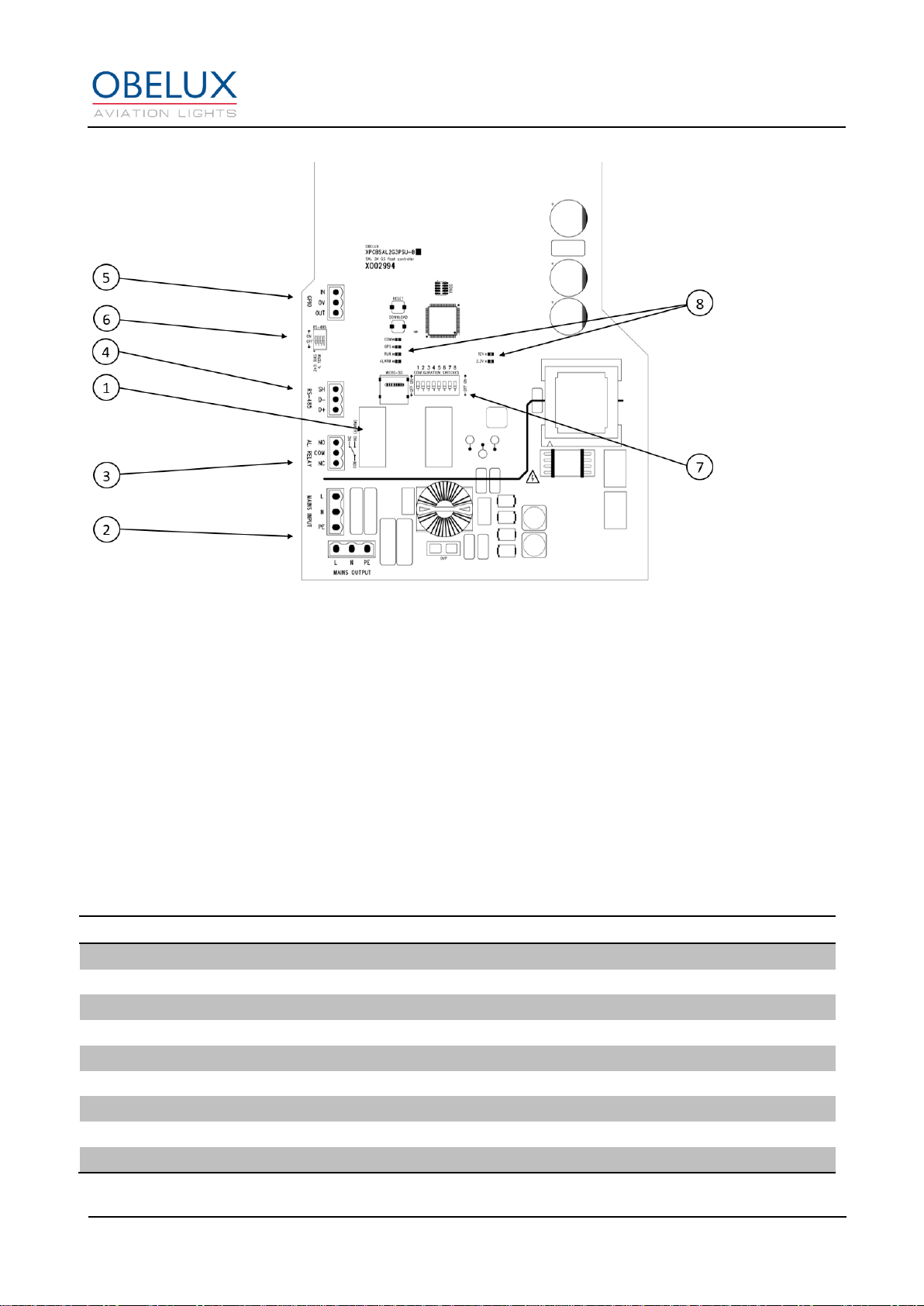
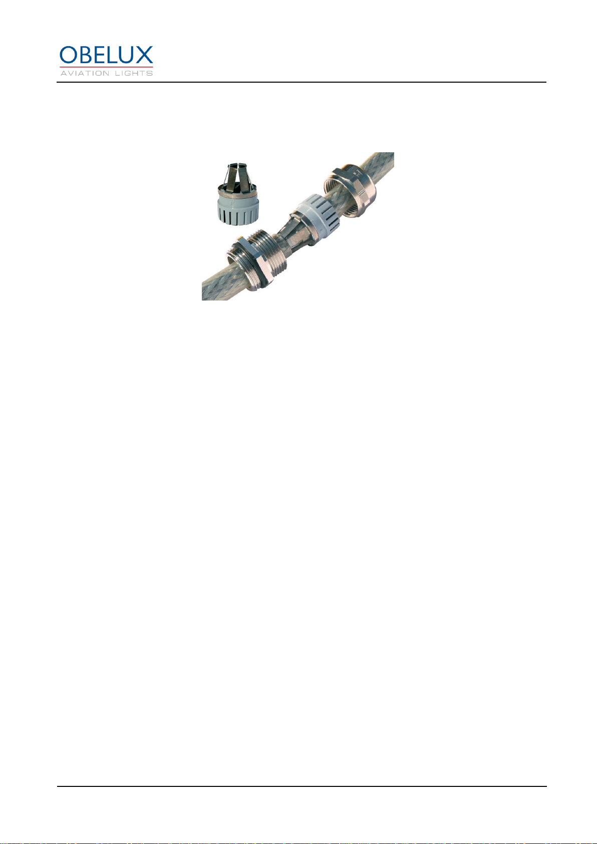
5.2 WIRING ................................................................................................................................................................. 8
5.2.1 Mains input (ACW versions and L864-MX-GA).......................................................................................... 11
5.2.2 Mains output (ACW versions) ................................................................................................................... 11
5.2.3 DC input (DC versions)............................................................................................................................... 12
5.2.4 DC output (DC versions) ............................................................................................................................ 12
5.2.5 Alarm Relay Output................................................................................................................................... 12
5.2.6 RS485 input (not available with L864-MX-GA).......................................................................................... 12
6CONFIGURATION ...............................................................................................................................................13
6.1 STAND-ALONE MODE.............................................................................................................................................. 14
6.2 MODBUS MODE .................................................................................................................................................... 16
6.3 TEST MODE........................................................................................................................................................... 17
6.4 L864-MX-GA CONFIGURATION .............................................................................................................................. 17
7OPERATION........................................................................................................................................................18
7.1 STAND-ALONE OPERATION....................................................................................................................................... 18
7.2 MODBUS OPERATION ............................................................................................................................................. 18
7.3 CAUSES FOR ALARM ............................................................................................................................................. 18
7.4 ONBOARD LEDS.................................................................................................................................................... 19
7.5 TROUBLESHOOTING................................................................................................................................................ 20
7.6 SPARE PARTS......................................................................................................................................................... 20
7.7 PACKAGING DETAILS ............................................................................................................................................... 20
8MAINTENANCE...................................................................................................................................................21
8.1 UPDATING DEVICE SOFTWARE................................................................................................................................... 21
8.2 REPLACING THE GLASS COVER ................................................................................................................................... 23
8.3 REPLACING MAIN CIRCUIT BOARD .............................................................................................................................. 25

MI SERIES –Manual (v1.7)
Obelux Oy, Kutomotie 6 B, 00380 Helsinki FINLAND
© Obelux Oy 2017 Technical information in this document is subject to change without notice.
Page: 3(28)
1 CHANGE LOG
Version
Date:
Description:
Author
0.1
25.10.2016
Document created
AHa
0.9
16.12.2016
Document draft released for internal review
AHa
1.0
23.12.2016
Document release
AHa
1.1
2.1.2017
New RED flashing mode added
AHa
1.2
31.1.2017
Photocell operation mode added
AHa
1.3
23.03.2017
Troubleshooting, Spare parts, Packaging, DC models
added.
AHa
1.4
03.04.2017
Photocell operation explained in more detail
AHa
1.5
12.07.2017
Installation chapter improved. Added pictures.
AHa
1.6
06.10.2017
GPS lock indicator LED functionality revised.
Photocell limits added for time of day changes.
AHa
1.7
15.11.2017
Maintenance chapter and L864-MX-GA added
AHa

MI SERIES –Manual (v1.7)
Obelux Oy, Kutomotie 6 B, 00380 Helsinki FINLAND
© Obelux Oy 2017 Technical information in this document is subject to change without notice.
Page: 4(28)
2 ABOUT THIS DOCUMENT
This document describes the installation and setup of the MI series light head unit, DIP switch effects and
operation of the unit on practical level.
CP
Control Panel
FPM
Flashes Per Minute
Table 1: Acronyms and Abbreviations

MI SERIES –Manual (v1.7)
Obelux Oy, Kutomotie 6 B, 00380 Helsinki FINLAND
© Obelux Oy 2017 Technical information in this document is subject to change without notice.
Page: 5(28)
3 ABOUT THIS PRODUCT
Obelux MI series obstruction lights provide 2000cd RED (Medium-Intensity Type B/C) light. Some models
also feature Night Vision Goggle (NVG) compliant infrared light (850nm).
The MI series lights support both Stand-alone and Modbus operation. In Stand-alone mode, no external
controllers are required to run the product. In most use cases, mounting the standalone aviation obstruction
light and connecting power supply cable are the only actions needed to operate. In Modbus operation, the
light is controlled with a Obelux controller as a part of an aviation light system.
The models come with built-in photocell that can drive the transitions between day, twilight and night modes.
The light operation is based on an embedded microcontroller on the light main circuit board.
Figure 1: Main functional parts of light head
1. Lug (for lifting the light)
2. Spirit level (for levelling the light during installation)
3. Location of photocell
4. Service access hatch
5. Cable glands

MI SERIES –Manual (v1.7)
Obelux Oy, Kutomotie 6 B, 00380 Helsinki FINLAND
© Obelux Oy 2017 Technical information in this document is subject to change without notice.
Page: 6(28)
Figure 2: Main circuit board of the light head
1. Software version label
2. Mains power supply connectors
3. Alarm relay connector
4. Communications network connector (RS-485)
5. External signal input connector (GPIO)
6. RS485 termination DIP switches (DIP4)
7. Configuration DIP switches (1-8)
8. Status LEDs
3.1 Versions
Obelux MI series is available as the following models:
Order code
Output
Op. volt.
GPS synch
Infrared
CCV*
Packing dimensions
MI-ACWGAM
2 000cd
90-265VAC
Yes
No
No
460x330x330mm, 12,7kg
MI-ACWIRGAM
2 000cd
90-265VAC
Yes
Yes
No
460x330x330mm, 12,7kg
MI-ACWCCVGAM
2 000cd
90-265VAC
Yes
No
Yes
460x330x330mm, 12,7kg
MI-ACWCCVIRGAM
2 000cd
90-265VAC
Yes
Yes
Yes
460x330x330mm, 12,7kg
MI-DCGAM
2 000cd
20-60VDC
Yes
No
No
460x330x330mm, 12,7kg
MI-DCIRGAM
2 000cd
20-60VDC
Yes
Yes
No
460x330x330mm, 12,7kg
MI-DCCCVGAM
2 000cd
20-60VDC
Yes
No
Yes
460x330x330mm, 12,7kg
MI-DCCCVIRGAM
2 000cd
20-60VDC
Yes
Yes
Yes
460x330x330mm, 12,7kg
L864-MX-GA
2 000cd
90-265VAC
Yes
No
No
460x330x330mm, 12,7kg
*Cold Climate Version

MI SERIES –Manual (v1.7)
Obelux Oy, Kutomotie 6 B, 00380 Helsinki FINLAND
© Obelux Oy 2017 Technical information in this document is subject to change without notice.
Page: 7(28)
4 SAFETY INSTRUCTIONS
In this section, you will find general safety instruction for the device. Please read the instructions carefully
before installing or using the device to avoid any personal, environmental or material damages.
4.1 General considerations
Install device observing manufactures installation guide.
Use only cables and connectors specified by the manufacturer.
Keep your device away from heat sources, dust, smoke or other harmful substances.
Do not add or remove any components inside the device unless otherwise approved by the manufacturer.
Do not spill food or other liquids on device
If you have any error situation with the device, do not try to fix it by yourself, contact your reseller.
4.2 Environmental considerations
The European Parliament and the Council of European Union issued directive 2012/19/EU to contribute to
sustainable production and consumption by, as a first priority, the prevention of WEEE and, in addition, by
the re-use, recycling and other forms of recovery of such wastes so as to reduce the disposal of waste and
to contribute to the efficient use of resources and the retrieval of valuable secondary raw materials.
Obelux aviation obstacle light products sold inside European Union can be returned to manufacturer if no
local WEEE separate collection and re-use services are available. Please contact Obelux for details.
Obelux does not refurbish returned items but forwards them to authorized WEEE treatment facility.
4.3 Personal considerations
HIGH VOLTAGE! Device contains high voltage which is very dangerous to human beings. Any direct contact
to high voltage could lead to serious injury, worst case even death.

MI SERIES –Manual (v1.7)
Obelux Oy, Kutomotie 6 B, 00380 Helsinki FINLAND
© Obelux Oy 2017 Technical information in this document is subject to change without notice.
Page: 8(28)
5 INSTALLATION
5.1 Device installation
Mount the obstruction light to selected mounting point using quality-made fasteners. This aviation obstruction
light comes with four bolt holes to mount this product securely. One of the mounting points is not painted.
This mounting point can be used as additional grounding. Level the light using spirit level (bubble level) if the
mounting point is not already levelled. Tighten bolts & nuts. Obelux recommends 100 Nm tightening torque
for M12 hot-dipped 8.8 bolts with suitable washer between bolt and mounting plate. When the service access
hatch (door) is open, check that there is no inflow of water (incl. hail and snow) into aviation obstacle light.
Photocell is located on top of the light. Photocell should have an uninterrupted view of the sky to work
correctly. All dimensions are in millimetres (mm).
Figure 3: Dimensions
5.2 Wiring
Route cables using cable glands on side of the light head. Connect the cable wires securely to appropriate
terminal block connectors. Connectors can be disconnected from the terminals on the main circuit board for
easier access. Second row of terminals in the Alarm relay / RS485 connector can be used to distribute alarm
and data signals to next light head.
Figure 4: Terminal block connector
Mains Power
Alarm relay / RS485 data

MI SERIES –Manual (v1.7)
Obelux Oy, Kutomotie 6 B, 00380 Helsinki FINLAND
© Obelux Oy 2017 Technical information in this document is subject to change without notice.
Page: 9(28)
Figure 5: Wiring the Mains Input
Figure 6: Distributing power and data to next light head

MI SERIES –Manual (v1.7)
Obelux Oy, Kutomotie 6 B, 00380 Helsinki FINLAND
© Obelux Oy 2017 Technical information in this document is subject to change without notice.
Page: 10(28)
Make sure that all unused glands or gland holes are sealed. There are two different size cable glands used
on the device. Follow the illustration below to achieve desired EMC protection with the EMC glands:
Cable gland M25 for 11-16 mm cable diameter
Please follow these instructions when routing cable via a cable gland:
1. Partially expose the braided screen by removing the outer sheath of the cable at a length of approx.
10 mm.
2. Insert the cable through the dome nut and the gland body until the contact spring is pressed against
the braided screen.
3. Firmly screw on dome nut.

MI SERIES –Manual (v1.7)
Obelux Oy, Kutomotie 6 B, 00380 Helsinki FINLAND
© Obelux Oy 2017 Technical information in this document is subject to change without notice.
Page: 11(28)
Figure 7: Light head terminals
5.2.1 Mains input (ACW versions and L864-MX-GA)
Mark
Description
Information
L
Live terminal
Connect the mains power supply in into these screw connectors.
Colours are typically brown (for Live) and blue (for Neutral)
N
Neutral terminal
PE
Protective earth
Connect protective earth into this screw connector. PE line is typically
indicated with yellow/green shield on the wire.
Single-phase supply with Protective Earth. Tighten the connector screws using flat-head (straight)
screwdriver.
Conductor cross-section
0.2mm² - 2.5mm²
5.2.2 Mains output (ACW versions)
Mark
Description
Information
L
Live terminal
Connect the mains power supply in into these screw connectors.
Colours are typically brown (for Live) and blue (for Neutral)
N
Neutral terminal
PE
Protective earth
Connect protective earth into this screw connector. PE line is typically
indicated with yellow/green shield on the wire.
This terminal is used to distribute power from the light head to the next. Tighten the connector screws using
flat-head (straight) screwdriver.
Conductor cross-section
0.2mm² - 2.5mm²

MI SERIES –Manual (v1.7)
Obelux Oy, Kutomotie 6 B, 00380 Helsinki FINLAND
© Obelux Oy 2017 Technical information in this document is subject to change without notice.
Page: 12(28)
5.2.3 DC input (DC versions)
Mark
Description
Information
+
Positive
Power supply input positive
-
Negative
Power supply input negative
GND
Ground
Protective earth
Tighten the connector screws using flat-head (straight) screwdriver.
Conductor cross-section
0.2mm² - 2.5mm²
5.2.4 DC output (DC versions)
Mark
Description
Information
+
Positive
Power supply output positive
-
Negative
Power supply output negative
GND
Ground
Protective earth
This terminal is used to distribute power from the light head to the next. Tighten the connector screws using
flat-head (straight) screwdriver.
Conductor cross-section
0.2mm² - 2.5mm²
5.2.5 Alarm Relay Output
Mark
Description
Information
NO
Normally Open
In alarm, connected with COM
COM
Common
Common relay contact
NC
Normally Connected
During normal operations, connected with COM
Unused alarm relay connectors can be left floating i.e. no wiring there is required. Push-in spring connection.
Conductor cross-section
0.2mm² - 2.5mm²
5.2.6 RS485 input (not available with L864-MX-GA)
Mark
Description
Information
D+
Data +
RS485 non-inverting pin
D-
Data -
RS485 inverting pin
SH
Shield
Shield
The RS-485 network (bus) input. Push-in spring connection.
Conductor cross-section
0.2mm² - 2.5mm²

MI SERIES –Manual (v1.7)
Obelux Oy, Kutomotie 6 B, 00380 Helsinki FINLAND
© Obelux Oy 2017 Technical information in this document is subject to change without notice.
Page: 13(28)
6 CONFIGURATION
Open the two screws that secure the service access door to the chassis using a hex key. Using the DIP
switches visible and accessible via service access opening, configure the desired parameters into the light.
DIP switches are numbered 1-8, the lowest number (1) being on the leftmost edge of the red/white DIP
switch block looked from service access door. Embedded software in the obstruction light reads
configuration switches regularly. Configuration change becomes effective within few seconds.
The light can be configured between two different operating modes. Reset is needed when changing
between Stand-alone mode and Modbus mode. Configuring L864-MX-GA light is covered in chapter 6.4.
Stand-alone mode: In this mode, the light operation is configured with DIP switches. No additional
controllers are needed.
Modbus mode: In this mode, the light is being controlled with an additional Obelux controller.
Figure 8: Location of the DIP switches

MI SERIES –Manual (v1.7)
Obelux Oy, Kutomotie 6 B, 00380 Helsinki FINLAND
© Obelux Oy 2017 Technical information in this document is subject to change without notice.
Page: 14(28)
6.1 Stand-alone mode
The light is in stand-alone mode when the DIP 8 is off.
DIP switch
Stand-alone (A) or Modbus (M)
8
off
Stand-alone (A)
on
Modbus (M)
Flashing mode of light is selected with DIPs 1-3. Configuring L864-MX-GA light is covered in chapter 6.4. All
MI series lights don´t have infrared light included. Using IR configuration in a non-IR light will give an
unnecessary alarm. Flash pulse length for the RED can be selected as 50% (50:50) of the selected flash rate
or to fixed 200ms. Photocell light limit for the day mode is 1600lux and 157lux for the night mode.
DIP switch
Light type (MI series)
1
2
3
Day / Twilight
Night
off
off
off
OFF
2 000cd red, 50:50
on
off
off
OFF
2 000cd red and infrared, 50:50
off
on
off
OFF
2 000cd red, 200ms
on
on
off
OFF
2 000cd red and infrared, 200ms
off
off
on
OFF
2 000cd red, steady burning
on
off
on
OFF
2 000cd red and infrared, steady burning
off
on
on
2 000cd red
200cd red and infrared 50:50
on
on
on
Reserved (if selected, the light will be OFF)
Flashing rate (FPM) is selected with DIPs 4-5. When using the 30fpm setting the photocell night limit is
changed to 54lux.
DIP switch
Flash rate
4
5
off
off
20 fpm (flashes per minute)
on
off
30 fpm
off
on
40 fpm
on
on
60 fpm
Photocell operation is configured with DIP 6. Night mode limit for the photocell is 400lux. If photocell is
disabled the light will operate as specified in the Night column of the Light type table (DIPs 1-3).
DIP switch
Photocell mode
6
off
Photocell is disabled
on
Photocell controls the light
Using DIP switch 7, the obstruction light can be set to operate as master in network. Only one obstruction
light shall be master in a network domain. Master unit broadcasts time and illumination data to slave units.
Time is typically received from GPS and illumination information comes from photocell. If the information flow
from master unit to slave units is interrupted, the slave units will use local photocell setting and local clock
(time) in their operations. As data flow resumes, the slaves automatically synchronise themselves with
master unit.
DIP switch
Master/Slave mode
7
off
This device is slave
on
This device is master

MI SERIES –Manual (v1.7)
Obelux Oy, Kutomotie 6 B, 00380 Helsinki FINLAND
© Obelux Oy 2017 Technical information in this document is subject to change without notice.
Page: 15(28)
RS-485 bus should be terminated with on-board 120 ohm resistors on both ends of this communications bus.
Turn on DIP4 on from the termination DIP switches. Location of the termination DIP switches can be seen in
Figure 6.

MI SERIES –Manual (v1.7)
Obelux Oy, Kutomotie 6 B, 00380 Helsinki FINLAND
© Obelux Oy 2017 Technical information in this document is subject to change without notice.
Page: 16(28)
6.2 Modbus mode
The light is in Modbus mode when the DIP 8 is on. Light is being controlled with an Obelux controller.
DIP switch
Stand-alone (A) or Modbus (M)
8
off
Stand-alone (A)
on
Modbus (M)
Configuration DIP switches 1-4 are used to give the light RS485 bus address. Duplicate addresses on the
same bus are not allowed. Give lights connected to the same communication bus an address starting from
one.
DIP switch
Modbus Address
1
2
3
4
on
off
off
off
Address 01
off
on
off
off
Address 02
on
on
off
off
Address 03
off
off
on
off
Address 04
on
off
on
off
Address 05
off
on
on
off
Address 06
on
on
on
off
Address 07
off
off
off
on
Address 08
on
off
off
on
Address 09
off
on
off
on
Address 10
on
on
off
on
Address 11
off
off
on
on
Address 12
on
off
on
on
Address 13
off
on
on
on
Address 14
on
on
on
on
Address 15
RS-485 bus should be terminated with on-board 120 ohm resistors on both ends of this communications bus.
Turn on DIP4 on from the termination DIP switches. Location of the termination DIP switches can be seen in
Figure 6.

MI SERIES –Manual (v1.7)
Obelux Oy, Kutomotie 6 B, 00380 Helsinki FINLAND
© Obelux Oy 2017 Technical information in this document is subject to change without notice.
Page: 17(28)
6.3 Test mode
To enter test mode set DIP 7 and DIP 8 on. All other DIPs are set off. The light will enter test mode when
power is turned on. To leave test mode turn off DIP 7 and DIP 8 and turn off the power. When power is
turned on again the light returns to normal operation.
DIP switch
Test mode
7
8
on
on
Test mode enabled. All other DIPs are off.
Light mode is selected with DIPs 1-3. There is normally a delay when changing time day modes (day, twilight
and night) based on photocell data. Using accelerated photocell mode will decrease the delay to a minimum.
DIP switch
Light mode
1
2
off
off
Accelerated photocell light behaviour
on
off
RED light only
off
on
IR light only
on
on
Reserved
Flashing rate (FPM) is selected with DIPs 4-5.
DIP switch
Flash rate
4
5
off
off
Steady
on
off
20 fpm (flashes per minute)
off
on
40 fpm
on
on
60fpm
The light can be dimmed with using DIP 6 and DIP 7. Dimming is light brightness as percentage of full
power.
DIP switch
Dimming
6
7
off
off
100%
on
off
30%
off
on
100%
on
on
10%
6.4 L864-MX-GA Configuration
No configuration is needed for L864-MX-GA light. All DIP switches should be in off.
DIP switches
Operation
Day (>645lx)
Twilight (645>x>54lx)
Night (<54lx)
all off
OFF
OFF
2 000cd red, 30fpm (50:50)

MI SERIES –Manual (v1.7)
Obelux Oy, Kutomotie 6 B, 00380 Helsinki FINLAND
© Obelux Oy 2017 Technical information in this document is subject to change without notice.
Page: 18(28)
7 OPERATION
MI series light can be configured in to two operation modes. These two operation modes are explained in the
following chapter.
7.1 Stand-alone operation
In stand-alone operation, the light is configured with the DIP switches. No additional controllers are needed.
Light head will use its internal photocell to determine the time of day (day, twilight or night). The light will
change its flashing mode based on photocell data and how the user has configured the light. Light heads will
synchronize their flashing with the built-in GPS module. After light head start-up, it will take some time for the
light head to acquire a GPS lock.
7.2 Modbus operation
In Modbus operation, the light is being controlled with a Obelux controller. If connection is lost the controller
the light will keep working on its own. It will use its internal photocell and GPS to synchronize flashing and
determine the time of day. The light will return to normal operation when the connection is recovered.
7.3 Causes for ALARM
The following events can cause an ALARM:
•Internal power failure
•Light source failure, including decreased intensity level below rated level of light
•Loss of GPS synchronization signal or GPS module failure
•Incorrect photocell operation
The ALARM led will turn on and ALARM relay will activate.

MI SERIES –Manual (v1.7)
Obelux Oy, Kutomotie 6 B, 00380 Helsinki FINLAND
© Obelux Oy 2017 Technical information in this document is subject to change without notice.
Page: 19(28)
7.4 Onboard LEDs
Status indication LEDS are located on the controller board. Some of the status indicators have three
operating states (off, lit and blinking).
Figure 9: Location of the status LEDs
Obelux MI series lights have five status LEDs on the controller board. These status LEDs are visible only
when service access hatch is open.
LED
Description
3.3V
Internal operating voltage (GREEN)
LED OFF: Power off
LED ON: Unit is powered on
12V
Internal operating voltage (GREEN)
LED OFF: Power off
LED ON: Unit is powered on
GPS
GPS fix
LED OFF: No GPS fix
LED FLASHING: Light GPS module has fix on GPS place and time. Light is not yet fully
synchronized.
LED ON: Light GPS module has fully resolved the UTC time. It may take several minutes
for the GPS module to receive the necessary data.
COM
Communication (GREEN)
LED OFF: Waiting for external signals
LED FLASHING: Master-slave communications occurring on the network

MI SERIES –Manual (v1.7)
Obelux Oy, Kutomotie 6 B, 00380 Helsinki FINLAND
© Obelux Oy 2017 Technical information in this document is subject to change without notice.
Page: 20(28)
RUN
Synchronization (GREEN)
LED OFF: All outputs are off
LED ON: At least one output is active. Led is flashing at same time and frequency as the
aviation light.
ALARM
Alarm indicator (RED)
LED OFF: Normal operation, no alarms
LED ON: Active alarm condition
7.5 Troubleshooting
The light doesn´t start
•No power (check that the 3V3 status LED is illuminated)
•Incorrect configuration (check DIP switches, make sure Test mode is turned off)
•Loose wires (check that all wires are properly seated in terminal block connectors)
•Do not exceed maximum operating voltage. Mains power supply input is protected with overvoltage
protection circuit that is tuned to stated operating voltage range.
No Modbus data connection to Obelux controller
•Check DIP settings. Check that light has a correct Modbus address and that there are no conflicting
addresses. Make sure light is configured to Modbus mode (DIP8).
•Too many RS-485 termination resistors (120ohm) on the same RS-485 communication bus. Only the
last light on the bus should have the termination resistor in use.
•Check Modbus data wiring
Light does not change modes between day, twilight and night
•Check that the photocell has an uninterrupted view of the sky
•Check that there are no external light sources that interfere with the photocell
•Photocell is sampled once in a minute and read value are averaged to avoid sudden state changes.
Unless test mode is enabled, it takes approx. three (3) minutes to change system state between day,
twilight and night.
Light does not flash in sync
•GPS antenna is mounted on top of obstruction light. Antenna needs non-blocked view to GPS
satellites in orbit. After start-up, GPS receiver may take up to 30min to obtain correct time data from
GPS satellites. This operation requires data from several GPS satellites.
7.6 Spare parts
Part code Description
SSAL2G3PSU Main board for MI-light
GC-MI17 Glass Cover with gaskets for MI-light
7.7 Packaging details
Box dimension: 33 X 33X 46cm
Weight: 12,70Kg
Box material: Cardboard outer box with extra cushion inside
This manual suits for next models
9
Table of contents
Other OBELUX Light Fixture manuals