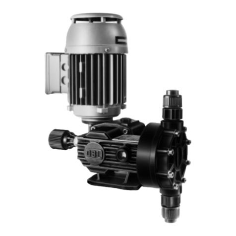
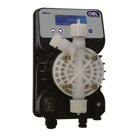
OBL X9 Series User manual

OBL
JOB No.
CUSTOMER
CUSTOMER
ORDER No.
METERING
PUMP
TYPE
ANNEXES
ITEM/S
SERIAL
NUMBER/S
P
PO
OS
SI
IT
TI
IV
VE
E
R
RE
ET
TU
UR
RN
N
-
-
A
AP
PI
I
6
67
75
5
PROCESS
HYDRAULIC DIAPHRAGM
METERING PUMPS
SERIES
L
Doc. N° UT4336 Rev. Lang. ENG 1st Issue 14.12. 9
Prepared E. SERRAINO
Checked V. D'ADDIO Replace UT2694
Rev.
Revised sections Checked Date
TRANSLATION OF ORIGINAL INSTRUCTIONS
ATTENTION: Industrial machinery not intended for use y
non-professional operators.
These instructions are intended for qualified personnel.
OPERATING MANUAL
English
HYDRAULIC SYSTEM WITH BUILT-IN SAFETY VALVE, MECHANICALLY
ACTUATED OIL REPLENISHING VALVE AND AIR-BLEED VALVE
X
X
9
9
V
VE
ER
RS
SI
IO
ON
N

X9 Series metering pumps Operating manual
Page 2 Copyright © - OBL Metering pumps - All rights reserved File: UT-4336 – Rev.0
GB
INDEX
1.
INTRODUCTION ......................................................................................................................................... 4
1.1
RECEIVING INSPECTION ........................................................................................................................... 4
1.2
SUPPLY CONDITIONS ................................................................................................................................ 4
1.3
NOTES ON ELECTROMAGNETIC COMPATIBILITY ......................................................................................... 4
1.4
USE IN POTENTIALLY EXPLOSIVE AREAS .................................................................................................... 4
2.
GENERAL INFORMATION ........................................................................................................................... 4
2.1
PERSONNEL RESPONSIBLE FOR MACHINE OPERATION................................................................................ 5
2.1.1
"Operator" personnel ........................................................................................................................ 5
2.1.2
"Mechanical Maintenance" personnel .................................................................................................. 5
2.1.3
"Electrical Maintenance" personnel ..................................................................................................... 5
2.2
TESTING AND GUARANTEE ........................................................................................................................ 5
2.2.1
Testing ............................................................................................................................................ 5
2.2.2
Guarantee ....................................................................................................................................... 5
2.3
INSTRUCTIONS FOR REQUESTING SPARE PARTS ........................................................................................ 6
2.3.1
Spare parts ...................................................................................................................................... 6
2.3.2
Changes and manufacturing of spare parts without approval ................................................................ 6
2.4
LIABILITY EXCLUSION .............................................................................................................................. 6
2.5
RESTRICTIONS REGARDING THIS DOCUMENT ............................................................................................ 6
3.
SAFETY WARNINGS ................................................................................................................................... 6
3.1
SYMBOLS AND SUGGESTIONS IN THESE INSTRUCTIONS ............................................................................. 7
3.2
DANGER ................................................................................................................................................... 7
3.3
INDIVIDUAL PROTECTIVE EQUIPMENT ....................................................................................................... 7
3.4
ADDITIONAL NOTE FOR ATEX PUMPS ........................................................................................................ 7
3.5
SUITABILITY VERIFICATION FOR EFFECTIVE APPLICATION/USE .................................................................. 8
4.
TRANSPORT, HANDLING AND STORAGE ................................................................................................... 8
4.1
TRANSPORT, LIFTING AND HANDLING ....................................................................................................... 8
4.2
STORAGE CONDITIONS ............................................................................................................................. 8
4.3
DIMENSIONS AND WEIGHTS ..................................................................................................................... 8
5.
DESCRIPTION ............................................................................................................................................ 8
5.1
IDENTIFICATION NAMEPLATE ................................................................................................................... 9
5.2
IDENTIFICATION CODE ............................................................................................................................. 9
5.3
AMBIENT AND DESIGN TEMPERATURE ..................................................................................................... 10
5.4
WORKING PRINCIPLE.............................................................................................................................. 10
5.5
THE FLOW RATE ..................................................................................................................................... 11
5.6
INTENDED USE ....................................................................................................................................... 11
5.7
REASONABLY EXPECTED IMPROPER USE .................................................................................................. 11
5.8
PROHIBITED USE.................................................................................................................................... 12
5.9
NOISE .................................................................................................................................................... 12
5.10
VIBRATIONS .......................................................................................................................................... 12
5.11
POWERING THE ELECTRIC MOTOR WITH INVERTER ................................................................................. 12
5.12
TECHNICAL DATA ................................................................................................................................... 12
5.12.1
Pumps type LY, LYH ....................................................................................................................... 12
5.12.2
Pumps type LK ............................................................................................................................... 13
5.12.3
Pumps type LN ............................................................................................................................... 13
5.12.4
Pumps type LP ............................................................................................................................... 13
5.13
FLOW RATE ADJUSTMENT SYSTEM .......................................................................................................... 13
5.13.1
Manual adjustment via graduate kno and linear vernier ................................................................... 13
5.13.2
Manual adjustment via handwheel with gravitational dial ................................................................... 13
5.13.3
Automatic adjustment y means of actuator ..................................................................................... 13
5.14
INTERNAL SAFETY VALVE ON HYDRAULIC OIL CIRCUIT ............................................................................ 13
6.
INSTALLATION AND COMMISSIONING .................................................................................................. 14
6.1
INSTRUCTIONS FOR PROPER INSTALLATION ............................................................................................ 14
6.1.1
Pump and pipeline fixing ................................................................................................................. 14
6.1.2
Connecting to plant pipelines ........................................................................................................... 14
6.1.3
Connecting the motor to the mains .................................................................................................. 15
6.2
SUCTION PIPELINE ................................................................................................................................. 15
6.2.1
Suction pipeline path ...................................................................................................................... 16
6.2.2
Suction pipeline for viscous liquids ................................................................................................... 17
6.2.3
Filter on suction pipeline ................................................................................................................. 17
6.3
DISCHARGE PIPELINE ............................................................................................................................. 18
6.3.1
External safety valve ...................................................................................................................... 19
ENGLISH

Operating manual X9 Series metering pumps
File: UT-4336 – Rev.0 Copyright © - OBL Metering pumps - All rights reserved Page 3
GB
6.3.2
Pulsation dampener ........................................................................................................................ 20
6.3.3
Pressure gauge .............................................................................................................................. 21
6.3.4
Cali ration pot ............................................................................................................................... 21
6.4
EXAMPLE OF PLANT FOR METERING PUMPS ............................................................................................. 21
6.5
ELECTRIC MOTOR INSTALLATION ............................................................................................................ 22
6.5.1
Flexi le joint coupling ..................................................................................................................... 22
6.5.2
Check and change the direction of rotation ....................................................................................... 22
6.6
DESIGN DATA CHECK .............................................................................................................................. 22
6.6.1
Environmental conditions ................................................................................................................ 22
6.6.2
Installation conditions ..................................................................................................................... 22
6.7
START-UP .............................................................................................................................................. 22
6.7.1
Checks efore start-up .................................................................................................................... 22
6.7.2
Checks during operation ................................................................................................................. 23
6.7.3
A normal conditions ....................................................................................................................... 23
6.7.4
Prolonged stops ............................................................................................................................. 23
7.
ROUTINE MAINTENANCE ......................................................................................................................... 23
7.1
OPERATING PRECAUTIONS ..................................................................................................................... 23
7.2
CONSULTING TECHNICAL DOCUMENTATION ............................................................................................ 24
7.3
PERIODIC OPERATIONS .......................................................................................................................... 24
7.3.1
Checks of normal operation ............................................................................................................. 24
7.3.2
Checks of electrical connections ....................................................................................................... 24
7.3.3
Checks of pump connection to plant pipeline .................................................................................... 24
7.3.4
General and surface cleaning........................................................................................................... 24
7.3.5
Protection against corrosion ............................................................................................................ 24
7.3.6
Verification of thermal protections ................................................................................................... 25
7.3.7
Painting check (if foreseen) ............................................................................................................. 25
7.3.8
Lu ricant oil check.......................................................................................................................... 25
7.3.9
Hydraulic oil system check .............................................................................................................. 25
7.4
RECOMMENDED SPARE PARTS ................................................................................................................. 25
7.4.1
Pumps with PLASTIC material pumphead ......................................................................................... 25
7.4.2
Pumps with METALLIC material pumphead ....................................................................................... 25
7.5
DISMANTLING, REPLACEMENT AND REASSEMBLY ..................................................................................... 25
7.5.1
Personnel qualifications - Customer service ....................................................................................... 26
7.5.2
Disconnecting electrical connections................................................................................................. 26
7.6
VALVE VERIFY AND/OR REPLACEMENT ..................................................................................................... 26
7.6.1
Pumps type LY, LYH ....................................................................................................................... 26
7.6.2
Pumps type LK, LN, LP .................................................................................................................... 27
7.7
LUBRICANT OIL CHANGE ......................................................................................................................... 27
8.
SPECIAL MAINTENANCE .......................................................................................................................... 28
8.1
TECHNICAL DOCUMENTATION................................................................................................................. 28
8.2
HYDRAULIC SYSTEM MAINTENANCE ........................................................................................................ 28
8.2.1
Hydraulic oil system change ............................................................................................................ 29
8.2.2
Diaphragm rupture signaling ........................................................................................................... 29
8.2.3
Diaphragm condition check ............................................................................................................. 29
8.2.4
Diaphragm replacement .................................................................................................................. 29
8.2.5
Hydraulic system oil filling ............................................................................................................... 31
8.2.6
Pumphead tightening torque values ................................................................................................. 33
8.2.7
Pumps with plastic material pumphead: Recommendations ................................................................ 33
8.3
DIAPHRAGM RUPTURE DETECTOR RESETTING ......................................................................................... 34
8.4
PUMPS TYPE LN, LP: KNOB ADJUSTMENT FRICTION SETTING ................................................................... 34
8.4.1
Increase the adjustment friction ...................................................................................................... 34
8.4.2
Reduce the adjustment friction ........................................................................................................ 34
8.5
BEARINGS REPLACEMENT ....................................................................................................................... 35
8.5.1
Reassem ling................................................................................................................................. 35
8.6
CHANGE OF INTERNAL SAFETY VALVE SET PRESSURE .............................................................................. 35
9.
OTHER INFORMATION ............................................................................................................................. 36
9.1
FAULTS AND OPERATING PROBLEMS ....................................................................................................... 36
9.1.1
Flowrate lower than expected .......................................................................................................... 36
9.1.2
Flow rate irregular or higher than expected ...................................................................................... 36
9.1.3
Overheating of pump ody and/or motor .......................................................................................... 36
9.2
DISCONNECTION FROM THE PLANT AND SENDING TO OBL FOR MAINTENANCE ......................................... 36
9.3
STORAGE FOR LONG PERIODS ................................................................................................................ 36
9.4
DISPOSAL AND DEMOLITION................................................................................................................... 36
1 .
MANDATORY INSTRUCTION FOR RETURNING GOOD IN OBL ............................................................... 37

X9 Series metering pumps Operating manual
Page 4 Copyright © - OBL Metering pumps - All rights reserved File: UT-4336 – Rev.0
GB
10.1
MANDATORY DIRECTIONS FOR SENDER .................................................................................................. 37
10.2
CLEANING OF EQUIPMENT ...................................................................................................................... 37
10.3
GOODS REJECTED TO SENDER ................................................................................................................ 38
11.
OVERALL AND SECTIONAL DRAWINGS ................................................................................................... 38
12.
CE CONFORMITY DECLARATION ............................................................................................................. 38
1. INTRODUCTION
The machines covered y the following "instructions" are intended for operation in industrial areas and therefore cannot e
treated as products for retail (consumer).
This document therefore contains information to be used by qualified personnel only.
They must also be integrated by laws and technical regulations in force and do not replace any plant regulation provisions or
any additional requirements, either legislative or non, which have een issued for safety purposes.
1.1 RECEIVING INSPECTION
All material relative to supply is delivered to the shipper in perfect condition after thorough final testing and packaging (where
applica le). Inspect goods immediately upon receipt and check that:
-the goods received correspond to the order made
-packaging (where applica le) has not undergone damage due to transport or has not een tampered with
If the packaging is damaged or tampered with, immediately check (quantity, quality and form):
-actual conditions of goods
-presence of all accessories or spare parts
ATTENTION: Should anomalies or damage be found IMMEDIATELY ISSUE A COMPLAINT WITH THE COURIER
and inform OBL as well. We suggest contacting OBL customer support before commissioning.
1.2 SUPPLY CONDITIONS
All X9 series pumps are supplied as follows:
-ready to e installed as specified in the jo order
-pre-tested in accordance with internal specifications
-pre-painted (where applica le)
-already equipped with lu ricant oil (where applica le)
1.3 NOTES ON ELECTROMAGNETIC COMPATIBILITY
The L series plunger pumps, if installed properly and with direct power supply from the mains, comply with emission limits set y
regulations relating to electromagnetic compati ility (EMC - General requirements for industrial environments).
Pumps for powering by means of inverters or other electronic equipment must be especially ordered for said
use. All checks and any necessary measures to comply with emission limits set by regulations shall be at charge and
responsability of the end user.
1.4 USE IN POTENTIALLY EXPLOSIVE AREAS
STANDARD operating X9 series pumps are not suitable for use in potentially explosive areas !
WARNING: X9 series pumps for hazardous areas must be especially ordered for said use ! In potentially
explosive atmospheres must be used only ATEX execution pumps with a flameproof motor !
All pumps in ATEX execution differ from NON ATEX (or standard execution) pumps in that they are fitted with a second
identification plate with specific indication of the data required y the directive.
2. GENERAL INFORMATION
The purpose of these instructions is to refer information deemed necessary for understanding as much as possi le a out and facilitating
the installation, commissioning, use and maintenance of L series version X9 hydraulic diaphragm metering pumps, hereafter
called, for short, X9 pumps.

Operating manual X9 Series metering pumps
File: UT-4336 – Rev.0 Copyright © - OBL Metering pumps - All rights reserved Page 5
GB
Although the X9 pumps include different and widely different models (see "Identifying code" and "Technical data"), the technical
information contained in this instructions manual are equally appropriate and applicable (except where expressly stated) for any
pump containing "X9" in its code.
OBL reserves the right to modify the characteristics of its products at any time to apply the latest technological innovations. The
information contained in this document is therefore su ject to change without notice.
2.1 PERSONNEL RESPONSIBLE FOR MACHINE OPERATION
Personnel, efore operating the machine, must e professionally trained (prefera ly an employee of the sector) and must have read
and understood the instructions contained in this manual.
The employer must instruct all staff on the risks of accidents and on devices and clothing to e used for individual safety, on the risks
arising from noise emission and on general provisions laid down y European Directives and legislation in the country of machine
installation.
2.1.1
"Operator" personnel
The term "Operator" is intended as personnel that carry out the following tasks on the machine:
-performs the functions needed for operation
-uses the adjustment and operating commands
-performs simple actions related to operation
-performs any cleaning and daily inspection operations
-reports defects or machine malfunctioning
The operator must work on the machine while protective guards are mounted and safety devices active
2.1.2
"Mechanical Maintenance" personnel
Intended as personnel that operates on the machine in all operating conditions and at all protection levels.
Performs all types of repairs or mechanical adjustments ut does not work on electrical installations.
2.1.3
"Electrical Maintenance" personnel
Intended as personnel that operates on the machine in all operating conditions and at all protection levels.
Performs all types of repairs or electrical installations adjustments, even in the presence of voltage.
2.2 TESTING AND GUARANTEE
2.2.1
Testing
Each OBL metering pump is a relia le quality product, su ject to careful final inspection to ensure their proper functioning and found
compliance with the specified performance. The final test results, if specifically requested y contract, are registered in special forms
and made availa le to the Customer. Pump which successfully pass the final tests is then la elled with a green sticker applied on the
product y the testing supervisor.
2.2.2
Guarantee
Metering pumps, as with all other OBL products, are guaranteed for a period of twelve (12) months of operation ut in any case no
longer than eighteen (18) months from the date of delivery (document of transport refers).
The guarantee covers the replacement, free of charge and ex-factory in Segrate (MILANO) ITALY, of any component found to e
defective in material or processing y the OBL technical office.
The guarantee IS NOT VALID in the following cases:
-components su ject to normal wear (e.g. gaskets, seals, O-rings);
-if installation and/or use do not meet the technical conditions of sale and instructions;
-if the pump has een tampered with or disassem led;
-if the pump has een sold to third parties.
ATTENTION: Always avoid disassemble or attempted repair of products still under guarantee, as doing so will
void the guarantee. Always contact OBL customer service for information.
In the case of a guarantee claim, the pump must e sent postage paid to the OBL factory in Segrate (MILANO) ITALY, accompanied y
a description of the anomaly complained.
For safety reasons BEFORE shipping, the sender MUST ALWAYS contact OBL customer service (Tel. +39-02-26919.1, info@o l.it)
and operate as indicated in point "Instructions for returning goods in OBL".

X9 Series metering pumps Operating manual
Page 6 Copyright © - OBL Metering pumps - All rights reserved File: UT-4336 – Rev.0
GB
2.3 INSTRUCTIONS FOR REQUESTING SPARE PARTS
Find and study the sectional drawing of the pump in use, if necessary contact OBL to o tain a copy. Analyze the conditions and identify
the damaged components. Using the nomenclature of the sectional drawing, make a list of the parts those components (mention the
sectional drawing num er and the component position code) and send to the OBL Sales Office, always specifying:
-type of metering pump (complete model num er)
-metering pump serial num er
-OBL jo n° (as an alternative to the serial num er)
N.B.: These informations can be found on metering pump nameplate.
2.3.1
Spare parts
Standard components (screws, nuts, all earings, etc…) are also availa le directly from specialised dealers. Replace any other
components with original OBL spare parts.
2.3.2
Changes and manufacturing of spare parts without approval
Modifications ARE NOT allowed. Original OBL spares and accessories are to be used in order to assure the
conformity with safety rules. OBL declines any responsibility in case of use of non-original parts and warranty will be
no longer valid.
2.4 LIABILITY EXCLUSION
OBL is una le to monitor the o servance of the instructions given in this manual, nor verify the actual working conditions and
installation of the equipment, the correct operation, the using and maintenance of the machines and accessories.
An incorrect installation, or misuse of the machine, may cause serious damage and may pose a danger to persons or property. Any
anomalies must e reported to the maintenance supervisor. The user is not authorized to tamper with the machine for any reason.
Attempts to disassemble, modify or tamper in general by unauthorized personnel will void the guarantee and
will release OBL from any liability for damage caused to persons or property resulting from such actions.
OBL is considered released from any lia ility in the following cases:
-improper installation;
-improper use of the machine y non-professional or inadequately trained operators;
-use not in compliance with regulations in the Country of use;
-lack of maintenance or improperly performed;
-use of non-original spare parts or incorrect parts for the model in question;
-total or partial failure to o serve the instructions;
-exceptional environmental events.
2.5 RESTRICTIONS REGARDING THIS DOCUMENT
This document is property of OBL S.r.l. together with the technical information contained in it. Modification, reproduction or copying (in
part or whole) without written permission is prohi ited. Violations will e prosecuted y law.
3. SAFETY WARNINGS
METERING PUMPS ARE INDUSTRIAL MACHINERY NOT INTENDED FOR USE BY NON-PROFESSIONAL
OPERATORS. THESE INSTRUCTIONS ARE INTENDED FOR QUALIFIED PERSONNEL.
FULLY AND CAREFULLY study these instructions before installing and starting the pump. Failure to respect
safety recommendations can damage the machine or compromise its operation.
For a correct handling and maintenance strictly follow present information. It is of key importance that these are read y the installer
and the maintenance supervisor. This document should e stored near the machine in a safe, dry place, and in any case always made
easily and readily availa le for future reference.
Keep always the instructions and warnings presents directly on the equipment in good and readable condition (replace
if necessary):
•Equipment nameplate
•Arrow indicating the motor direction of rotation

Operating manual X9 Series metering pumps
File: UT-4336 – Rev.0 Copyright © - OBL Metering pumps - All rights reserved Page 7
GB
•Warning and service information stickers
3.1 SYMBOLS AND SUGGESTIONS IN THESE INSTRUCTIONS
This sym ol indicates important information for preventing faults and/or damage to equipment or personnel.
This sym ol indicates danger due to the presence of electricity.
This sym ol indicates a danger that may cause an explosion.
This sym ol represents the metering pump schematically.
3.2 DANGER
Metering pumps are machines with dangerous parts. Therefore:
•improper use or tampering,
•removal of guards or disconnection of protective devices,
•inadequate inspection or maintenance can cause serious damage to persons or property.
In particular, personnel must be informed of danger due to:
-live parts
-rotating or moving parts
-handled fluid under pressure and/or corrosive
-hot surfaces
The safety supervisor must ensure and guarantee that:
-the machine is handled, installed, commissioned, inspected, maintained and repaired by qualified personnel only, that
must have:
-specific technical training and experience
-knowledge of technical regulations and applica le laws
-knowledge of general, national, local and plant safety requirements
-a ility to recognise and avoid all possi le danger.
Failure to follow these instructions, negligence or an incorrect or improper use of the machine y unauthorised and unqualified
personnel may cause risk to persons or property, resulting in cancellation of the guarantee y OBL.
The safety of these machines can be compromised if they are used improperly or tampered with.
Metering pumps must e used only if they are in perfect technical condition, also considering safety aspects and danger. The smooth
operation of these machines, their dura ility and operating efficiency depend on the o servance of these details. We declines any
responsi ility for odily injury or property damage caused y improper use of our equipment.
3.3 INDIVIDUAL PROTECTIVE EQUIPMENT
Any operation on the machine must e undertaken in compliance with safety regulations and safety warnings.
The safety supervisor must ensure compliance with applica le laws and safety regulations enacted for safety, and monitor that all
personnel are equipped and always use appropriate individual protective equipment.
Appropriate individual safety devices must always be used to ensure and safeguard the personal safety
of personnel, who must also be properly trained and professionally qualified.
3.4 ADDITIONAL NOTE FOR ATEX PUMPS
The X9 Series Hydraulic Diaphragm Metering Pumps in ATEX version comply with the rules concerning equipment and
protective systems for use in potentially explosive atmospheres in accordance with European Directive 94/9/CE dated 23/03/94, known
as ATEX directives.
•They meet the requirements of Group II Category 2, making them suita le for use in Zone 1/21 (No danger as a result of
predictable failure)

X9 Series metering pumps Operating manual
Page 8 Copyright © - OBL Metering pumps - All rights reserved File: UT-4336 – Rev.0
GB
•Consequently they are suita le for use in Zone 2/22, resulting classified in Group II Category 3 (No danger during normal
operation)
WARNING: The X9 pumps in ATEX execution are not suitable for use in zone /2 !
NOTE: In case of X9 pumps in ATEX execution, in addition to these instructions must be followed also the
warnings contained in "Metering pump safety instructions for potentially explosive atmospheres" (addendum to this
operating manual)
3.5 SUITABILITY VERIFICATION FOR EFFECTIVE APPLICATION/USE
All pumps are supplied in compliance with requirements esta lished under technical/sales negotiation and defined at time of order.
NOTE: The customer (end user and/or installer) is responsible for checking whether or not the pump is really
suitable for the application/use on the plant, this before the installation and subsequent machine start-up.
For ATEX pumps the customer/end user is responsi le to determine the effectiveness of the pump to be used in a
given plant, after having analysed the characteristics of danger existing in the installation location and in compliance with current laws
and those issued for safety purposes.
4. TRANSPORT, HANDLING AND STORAGE
4.1 TRANSPORT, LIFTING AND HANDLING
Unless otherwise agreed, the pumps are fixed and packaged in horizontal containers. Make sure that they cannot accidentally
tip over during transport or handling and that they are always place on a flat surface.
Verify that the device used (traspallets, forklift, hoist, etc...) is appropriate for the size and weight of the package/equipment and that
any lifting lugs on the machine are screwed down. In environments with temperatures elow -20 °C, lifting rings must e used with
caution ecause they could reak in low temperatures, causing damage to persons or equipment.
Lifting rings on the pump are sized to bear one-headed pump weight, therefore DO NOT use them to lift multi-
headed pumps. For those operations sling base-plate and use lifting ropes. Before removing ropes fix pumps safely to
the base. Pay attention, tilting danger !
4.2 STORAGE CONDITIONS
If not used immediately, the pumps should e stored with suita le covers in a temperate, dry, clean, vi ration-free and weatherproof
environment. Protect from soil moisture y placing the unit on shelves or wooden pallets. If the temperature is elow 0 °C, ensure that
it does not go lower than -20 °C.
If not specifically highlighted on the package, do not stack packaging, to prevent damage to the machine and to avoid tipping over or
falling that can create accidents. Ensure that access of unauthorised persons is not allowed in the storage location and that the floor or
shelf can support the weight of the machinery or equipment stored.
Before eing put pumps into operation, after eing stored for a long period, ring them to a temperate environment in order to sta ilise
the temperature. In case of storage in extreme conditions, e.g. in su -tropical or desert climates, take additional safety measures.
Particular storage conditions should be previously reported, in order to provide a suitable packaging.
4.3 DIMENSIONS AND WEIGHTS
Check the dimensions and overall gross weight of the package efore handling or lifting.
Unless otherwise agreed, the packaging ears such information (dimensions are expressed in millimetres and weight in kilograms).
5. DESCRIPTION
The L series version X9 metering pumps are all with dou le diaphragm (sandwich) pumphead with rupture detector on the head
and fall into the family of controlled volume alternative displacement pumps.
The crank is driven y a constant speed electric motor (1500 rpm) and the num er of diaphragm cycles is determined y the endless
screw – worm wheel internal reduction gear in an oil ath. The mechanically actuated replenishing hydraulic system ("intelligent"
diaphragm) makes the diaphragm immune from accidents or mishandling in discharge or suction.

Operating manual X9 Series metering pumps
File: UT-4336 – Rev.0 Copyright © - OBL Metering pumps - All rights reserved Page 9
GB
5.1 IDENTIFICATION NAMEPLATE
Each pump carries a nameplate for identification. Below is a representation of an example and its position:
Pump identification nameplate Nameplate position on the pump
1 = Pump identifying code 5 = Hydraulic circuit safety valve pressure cali ration ( ar)
2 = OBL Jo Num er (Order Confirmation) 6 = Year of manufacture
3 = Pump serial num er 7 = Item (where applica le)
4 = Maximum flow rate (l/h with adjustment at 100%)
Ensure that the machinery nameplate, the warning and service adhesives are always present and in good, legi le conditions. Otherwise,
provide to replace them.
Removal of the nameplate or alteration of data contained therein is NOT permitted for any reason.
5.2 IDENTIFICATION CODE
The L series version X9 hydraulic diaphragm metering pumps are identified y a code descri ed as follows:
../ LY SX 25 X9A 7 RF FA GS – M...
Number of pump heads:
NB: Present ONLY for multiple pumps.
Pump type:
LY, LYH, LK, LN, LP
Motor position (seen from the pump head side):
"..." for right-side motor (standard model, no code required)
…SX… for left-side motor
Plunger diameter:
The range differs according to pump model (view "Technical data").
Pumphead execution:
The range differs according to pump model (view "Technical data").
...A... pumphead material: AISI-316L
...P... pumphead material: PVC
...S... pumphead material: PVDF
...T... pumphead material: PTFE
Plunger strokes per minute:
The range differs according to pump model (view "Technical data").
Pump head model:
The range differs according to pump model (view "Technical data").
"..." for operating pressure: 0 ÷ 100 ar (standard model, no code required)
...TS... for operating pressure exceeding 100 ar
Connection type:
The range differs according to pump model (view "Technical data").
...F... UNI-DIN flanged connections
...FA... ANSI flanged connections
...RE... DIN-11851 food industry connections
Adjustment type:
"..." graduate kno and vernier adjustment (standard model, no code required)
...G... gravitational dial adjustment
...GS... gravitational dial with glycerin adjustment
...W... pneumatic actuator adjustment
...WA... pneumatic actuator adjustment with manual adjustment
...Z... electric actuator adjustment
continue …
Motor informations:
...M... motors supplied y OBL and assem led on the pump
1
2
3
4
6
7
!
5

X9 Series metering pumps Operating manual
Page 10 Copyright © - OBL Metering pumps - All rights reserved File: UT-4336 – Rev.0
GB
… follows
...MC motors supplied y the customer to OBL to e assem led on the pump
...M pump supplied to the customer WITHOUT a motor.
In case of special execution machines the constructive variations may differ from the a ove mentioned codes.
5.3 AMBIENT AND DESIGN TEMPERATURE
Unless differently agreed with the customer, the am ient design temperature range "Ta" of X9 pump can e:
–1 °C አ Ta አ +4 °C: Standard temperature range for all pump types
–1 °C አ Ta አ +6 °C: Standard temperature range for only some pump types
The ta le elow illustrates the maximum allowed temperature of pumped fluid ased on pump head material.
"STANDARD" pumpheads characteristics
METALLIC PLASTIC material pumphead
material pumphead PVC (P) PVDF (S)
PTFE (T) PP (PP)
HANDLED FLUID
Max. temperature +100 °C +40 °C +60 °C +30 °C +40 °C
Only on metallic pumpheads can e coupled to a warming jacket. The ta le elow illustrates the maximum allowed temperature of
warming fluid (additional code RF).
"RF" pumpheads characteristics
HANDLED FLUID
Max. temperature
WARMING FLUID
Max. temperature
METALLIC
material pumphead ≤+100 °C +130 °C
NOTE: During periodic inspection always check that temperatures respect limits here indicated !
The values contained in these ta les are applica le equally for each of the allowa le am ient temperatures "Ta".
5.4 WORKING PRINCIPLE
The L series version X9 hydraulic diaphragm metering pumps are all dou le hydraulic diaphragm (sandwich) with diaphragm
rupture detector. The "basic" detector is a pressure gauge placed directly on the head. During normal pump operation, it must
indicate "zero ( ) pressure", confirming that the diaphragms are intact.
NOTE: THE DETECTOR PRESSURE GAUGE DOES NO INDICATE THE PUMP OPERATING PRESSURE !
X9 hydraulic diaphragm pumps consist of a pumphead made of material (plastic or metallic) chemically compati le with the fluid to e
handled and coupled to a mechanism ody that incorporates the transmission reduction gear, the plunger thrust system and the flow
rate adjustment system.
The pump sectional drawing is usually attached to the present operating manual. In case of it is not attached or missing, see the point
"Hydraulic system oil filling" to consult pumphead section drawing or at least contact OBL customer service to receive an updated copy.
They are normally powered y an electric motor through a reduction gear type “endless screw and worm wheel” joined to a duct
mechanism. The latter consists of a connecting rod system with varia le eccentricity which determines the axial reciprocated movement
of the plunger; oth the mechanisms are in oil ath.
When moving, the connecting rod generates oth pump phases. During the discharge phase the connecting rod forces the plunger to
move forward, putting pressure on the oil cham er hydraulic circuit and determining the controlled deformation of the diaphragm,
su sequently the fluid in the pumphead moves to the discharge pipeline. During the suction phase the connecting rod pulls the plunger
ack which, creating a vacuum on the oil cham er, deforms the diaphragm again and causes the entrance of fluid in the pumphead.
The check valve on the pumphead controls input and output of fluid from the pumphead, determining flow direction.
A safety valve is installed on the oil cham er hydraulic circuit to safeguard the pump. If an excess of pressure exceeding its cali ration
is detected during operation, the valve opens, discharging a quantity of oil in the expansion tank equal to the displacement of the
plunger.
The flow rate adjustment system controls the volume of fluid pumped y varying the connecting rod eccentricity and, therefore, plunger
return stroke length. Standard adjustment is manual with graduate kno and linear vernier; alternatively (upon request), an automatic
adjustment system can e applied (see "Flow rate adjustment system").
X9 pumps fall into the family of alternative volumetric pumps characterized y adjusta le displacement.
The construction material of external components ensures high impact protection. With the exception of pumphead, the external pump
surfaces are treated to ensure high protection against corrosion. Metal parts are assem led to ensure correct and proper grounding.

Operating manual X9 Series metering pumps
File: UT-4336 – Rev.0 Copyright © - OBL Metering pumps - All rights reserved Page 11
GB
Multiple pumps are o tained y horizontal alignment of individual reduction gear, in which the endless screw shafts are fitted together
y means of a flexi le coupling. Each reduction gear has its own frequency of plunger strokes per minute, depending on the own worm
wheel transmission ratio.
5.5 THE FLOW RATE
X9 pumps flow rate is not continuous ut pulsating, generated y the alternating movement of the plunger (which deforms the
diaphragm) and the action of the check valve on the pumphead which determine flow direction (see figure 1). Pump flow rate is
adjusta le and increases or decreases in direct proportion to the variation of the plunger stroke.
The theoretical flow rate corresponds exactly to the volume descri ed y the movement of the diaphragm. The graphic representation
of its ehaviour is a straight line whose course is proportional to the adjustment system setting.
The actual flow rate is inevita ly lower than the theoretical flow rate, due to the volumetric efficiency of the pump. It varies depending
on the type and size of the pump, the nature and viscosity of the liquid to e pumped, working pressure, etc. (see figure 2).
5.6 INTENDED USE
X9 positive return hydraulic diaphragm pumps are destined for dosing liquid fluids (flamma le, acids, alkaline, solvents, etc.) at am ient
temperature or heated (see "Am ient and design temperature"), suita le for continuous service (24/24 hours of operation).
They can e used for the following applications:
-oil and gas extraction plants;
-chemical, petrochemical and power plants;
-food and agri usiness industries;
-pharmaceutical industries;
-water and wastewater treatment;
-in paper mills, on paper production lines;
-detergents production,
-water treatment plants.
Any other use is considered "IMPROPER USE" and is not allowed. OBL declines all responsibility for any
damage to persons or property and any kind of machine guarantee shall be considered void.
5.7 REASONABLY EXPECTED IMPROPER USE
It is improper to use the X9 pumps as follows:
-for dosing products differing from those esta lished during technical/sales negotiation and defined at time of order
-in a corrosive and stagnant atmosphere and closed in a poorly-ventilated location
-dosing in pressure without a pressure gauge installed on the discharge pipeline (see "Discharge pipeline - Pressure gauge")
-powered y means of an inverter or other electronic equipment unless explicitly ordered for this use
-with a motor faster than the original one (different polarity)
Figure 2
Figure 1

X9 Series metering pumps Operating manual
Page 12 Copyright © - OBL Metering pumps - All rights reserved File: UT-4336 – Rev.0
GB
-in potentially explosive areas unless explicitly ordered for this use
NOTE: It is the responsibility of the customer to verify that the pump is suitable for application/use before
installation and start-up. In case of doubt, do not improvise but contact OBL customer service.
5.8 PROHIBITED USE
It is prohi ited to use the X9 pumps as follows:
-in mining plants (underground);
-immersed in water (as su mersi le pumps)
IS PROHIBITED use the pumps without protective covers or with safety devices tampered with or damaged
X9 pumps in STANDARD version are not suitable for use in potentially explosive areas !
ATTENTION: X9 pumps in ATEX execution are not suitable for use in zone /2 !
5.9 NOISE
The ta le elow shows the average noise level (lp noise pressure level) emitted y L series spring return pumps, used within the limits
of use and installed in accordance with the instructions contained in the present operating manual.
These average values were detected on the prototype at a distance of 1 metre from the surface of the machine, at a height of 1,5
meters from the working surface and weighted according to curve A.
METALLIC MATERIAL PUMPHEAD PLASTIC MATERIAL PUMPHEAD
Pump max capacity
(Qmax)
Noise pressure level
(lp)
Pump max capacity
(Qmax)
Noise pressure level
(lp)
Qmax < 200 l/h < 65 dB(A) Qmax < 300 l/h < 65 dB(A)
200 l/h < Qmax < 400 l/h < 68 dB(A) 300 l/h < Qmax < 600 l/h < 68 dB(A)
400 l/h < Qmax < 600 l/h < 70 dB(A) 600 l/h < Qmax < 1000 l/h < 70 dB(A)
600 l/h < Qmax < 1000 l/h < 73 dB(A) 1000 l/h < Qmax < 1500 l/h < 73 dB(A)
1000 l/h < Qmax < 1500 l/h < 75 dB(A) 1500 l/h < Qmax < 2000 l/h < 75 dB(A)
Qmax > 1500 l/h < 78 dB(A) Qmax > 2000 l/h < 78 dB(A)
The employer must implement in the workplace, appropriate technical measures to minimise the risks arising from daily noise exposure
and as much as is necessary to ensure and safeguard the health of personnel in the working environment.
5.1 VIBRATIONS
X9 pumps do not fall into the category of direct human contact machines. Vi rations produced are not significant when pumps are
installed in accordance with these instructions. They are therefore less than 2,5 m/s
2
of acceleration and are not such as to cause
danger situations. If these situations should arise, stop the machine immediately and call the maintenance supervisor.
5.11 POWERING THE ELECTRIC MOTOR WITH INVERTER
The pumps must be especially ordered for powering by means of inverter. Otherwise the end user,
before their installation, must contact OBL to define new limits of use (Hz, pressure and flow rate) that will be
guaranteed only after a new nameplates fixed to the pump.
For a correct use of the pump, the user must comply with the power frequency range allowed y OBL, defined and including from 30Hz
to 80Hz. Moreover, IT MUST NOT EXCEED the max operating pressure indicated on the pump nameplate. This value is downgraded and
takes into account the maximum operating regime at maximum allowa le power frequency (80Hz).
User must also comply with any additional instructions provided y the inverter manufacturer. Solutions for meeting system
electromagnetic compati ility (EMC) requirements are the responsi ility of the installer.
5.12 TECHNICAL DATA
5.12.1
Pumps type LY, LYH
The full range of varia les is shown elow:
Plunger diameter: 10, 15, 20, 25, 30, 40, 50, 65
Pumphead execution: X9..., in com ination with: ...A, ...P, ...S, ...T, ...ALL, ...LOY, ...TI, ...SAF
Plunger strokes per minute: 25, 36, 50, 70, 95, 100, 118

Operating manual X9 Series metering pumps
File: UT-4336 – Rev.0 Copyright © - OBL Metering pumps - All rights reserved Page 13
GB
Pumphead version: "..." (STANDARD model, no code required) TL, TN, TS, OM, ON, RF, HT
Connections type: "..." (STANDARD connections, no code required), F, FA, RE
5.12.2
Pumps type LK
The full range of varia les is shown elow:
Plunger diameter: 10, 15, 20, 25, 30, 40, 50, 65, 80, 100
Pumphead execution: X9..., in com ination with: ...A, ...P, ...S, ...T, ...ALL, ...LOY, ...TI, ...SAF
Plunger strokes per minute: 25, 30, 42, 51, 60, 82, 102, 123
Pumphead version: "..." (STANDARD model, no code required) TL, TN, TS, OM, ON, RF, HT
Connections type: "..." (STANDARD connections, no code required), F, FA, RE
5.12.3
Pumps type LN
The full range of varia les is shown elow:
Plunger diameter: 15, 20, 25, 30, 40, 50, 65, 80, 100
Pumphead execution: X9..., in com ination with: ...A, ...P, ...S, ...T, ...ALL, ...LOY, ...TI, ...SAF
Plunger strokes per minute: 40, 47, 56, 68, 80, 96, 120
Pumphead version: "..." (STANDARD model, no code required) TL, TN, TS, OM, ON, RF, HT
Connections type: "..." (STANDARD connections, no code required), F, FA, RE
5.12.4
Pumps type LP
The full range of varia les is shown elow:
Plunger diameter: 30, 40, 50, 65, 80, 100, 120
Pumphead execution: X9..., in com ination with: ...A, ...P, ...S, ...T, ...ALL, ...LOY, ...TI, ...SAF
Plunger strokes per minute: 40, 47, 56, 68, 82, 97, 104, 120, 150
Pumphead version: "..." (STANDARD model, no code required) TL, TN, TS, OM, ON, RF, HT
Connections type: "..." (STANDARD connections, no code required), F, FA, RE
5.13 FLOW RATE ADJUSTMENT SYSTEM
Flow rate adjustment is continuous and regular and can e carried out either with the pump running or at rest. Anyhow the action it is
easier when pump is running, especially in case of large diameter plunger pumps.
5.13.1
Manual adjustment via graduate knob and linear vernier
Standard version provided when it is not specifically requested a particular adjustment system.
The graduated kno , turning on a fixed vernier, runs on a linear scale su -divided from 0 to 10. Zero (0)
on the kno lower edge is a reference index for setting the adjustment system to a desired flow rate
percentage value.
5.13.2
Manual adjustment via handwheel with gravitational dial
Manual version as an alternative to the " ase" version (supplied upon request).
Easy and quick manual adjustment com ined with precise, clear and immediate reading. The dial has a
percentage scale (from 0 to 100) and is equipped with two pointers. Each turn of the handwheel
corresponds to an adjustment change of 1% (millesimal reading).
ATTENTION: Adjustment via handwheel with gravitational dial indicator can be
decalibrated during transportor handling due to sudden accelerations, shock or capsizing.
Proceed as follows to reset decali rated adjustment:
-start up the pump and extract the gravitational dial from the handwheel y means of a screwdriver;
-turn the handwheel counter-clockwise, stopping when the plunger remains STOPPED (despite the motor running);
-turn the gravitational dial y hands ringing the pointers to 0%, then reposition the dial in the handwheel.
5.13.3
Automatic adjustment by means of actuator
The adjustment system can e automated (upon request) via the application of an electric or pneumatic actuator.
For information on actuator operation consult its specific operating manual.
5.14 INTERNAL SAFETY VALVE ON HYDRAULIC OIL CIRCUIT
All X9 pumps are equipped with an internal safety valve in the hydraulic circuit, located in the expansion tank (see the figures in
"Hydraulic system oil filling").

X9 Series metering pumps Operating manual
Page 14 Copyright © - OBL Metering pumps - All rights reserved File: UT-4336 – Rev.0
GB
This valve protects the pump from pressure excesses generated y the pump itself during operation (discharge closed or locked).
Therefore, only in this case can e avoided the installation of the external safety valve on the discharge pipeline, if this has een
installed to protect the pump.
The safety valve on the discharge pipeline is instead essential when system pressure can rise regardless of pump operation.
It is the responsibility of the user and/or installer to evaluate use or not of an external safety valve.
If during operation of the pump there is an excess of pressure higher than the setting of the internal safety valve, this valve opens and
discharges into the expansion tank a quantity of oil equal to the plunger displacement.
The internal safety valve opening is recognised and evident y means of:
-no pump flow (or at least greatly reduced)
-change of oil level in the tank
-increased noise of the pump (synchronised to the plunger strokes per minute)
6. INSTALLATION AND COMMISSIONING
6.1 INSTRUCTIONS FOR PROPER INSTALLATION
Because of the pumphead check valves work y gravity, it is essential that the housing valve axis must e perfectly vertical for proper
pump operation (also to prevent a normal wear of the valves).
Provide also for installation of the following equipment:
-a pressure gauge next the pump. It must e installed efore any other accessory installed on the discharge pipeline. Allows
to control the actual pump operating pressure (see "Discharge pipeline - Pressure gauge")
-an external safety valve immediately after the discharge connection and, in any case, efore the ON-OFF valve. Protects
the pump and the plant from any accidents caused y excessive pressure (see "Discharge pipeline - External safety valve")
-a suitable thermal overload device. It protects motor from overloads and/or short circuits
Protect the pump from product leaks from the plant and/or corrosion phenomena. Avoid to arrange pipeline
nor installing accessories directly above the pump. Avoid installation in a closed, corrosive or stagnant location.
For outdoor installations provide proper protection for the pump from direct weathering actions (rain, wind,
dust, humidity). Consider the benefits of using a shelter and/or sliding panels. These devices significantly raise the
level of efficiency and safety of the whole pump.
Provide adequate free space around the whole pump to allow inspections and/or dismantling. In particular from the pumphead side, in
correspondence with the adjustment system and from the motor side (see figure 3).
If the pump is installed outdoors, a shelter is recommended, especially when the pump is equipped with electric actuators or other
delicate devices.
Moreover, for pumps with PLASTIC material pumphead also provide:
-appropriate shelter from direct sunlight, to avoid thermal deformation of the pumphead
-periodic controls and/or adjustments of pumphead locking olt tightening torque
-periodic checks of the handled fluid temperature
-periodic checks of a sence of chemical leakages from pumps connections or plant pipelines
6.1.1
Pump and pipeline fixing
Do not install the pump directly on a concrete foundation ase. Use a steel aseplate make sure that is sta le and well leveled. Fix
securely the pump to the aseplate using olts and washers to ensure a proper load distri ution.
The pipelines must e supported independently and their weight must not urden or create tension on the pumphead.
Therefore, esides the aseplate, the pump needs a supporting framework for oth its suction and discharge pipelines.
6.1.2
Connecting to plant pipelines
On the discharge pipeline, to remove easily the pump from the plant, provide proper draining pipes near the pumphead.
We suggest to use short fittings to disassem le easily the flanged connections (see figure 4).

Operating manual X9 Series metering pumps
File: UT-4336 – Rev.0 Copyright © - OBL Metering pumps - All rights reserved Page 15
GB
After the pump discharge connection we recommend the use of a cross connection, oth to facilitate pump dismantling from the plant
and to allow (at a later time if necessary) the installation of a pressure gauge, safety valve, pulsation dampener.
Always verify complete sealing of fittings and pipe flanges, particularly on the suction side pipeline plant.
The entry of suctioned air prevents pump priming.
Before connecting the plant pipelines to the pump connections, it is absolutely necessary flush properly the
pipelines with water. Especially the suction pipeline and relevant feed tank. This preliminary flushing is often
underestimated by the installator and/or the end user; if this operation is not properly carried out, the pump will
become a collector of all foreing matters contained in the suction pipeline and tank, such as weld drops, gasket scraps,
soil and other stuff.
6.1.3
Connecting the motor to the mains
The metering pumps are always supplied with the use and maintenance instructions of the electric motor installed.
In addition, for ATEX pumps are also supplied the safety instructions, certification and ATEX conformity declaration.
Before carrying out electrical connections ensure that the mains supply voltage corresponds to that indicated
in the nameplate of the motor. Refer to the motor instructions manual and observe relevant provisions.
When for the mains ca le connections in used a ca le-gland, always choose it correctly according to the type of plant and properly for
the type of ca le used.
The ca le gland should e tightened so that the seal rings keep the necessary pressure:
-to prevent transmission of mechanical stress on the motor terminals
-to ensure mechanical protection (IP degree) of the terminal ox
NOTE: Always make the ground connection using the appropriate terminal in the terminal box.
6.2 SUCTION PIPELINE
To ensure a proper and smooth operation of the pump it is essential design correctly the suction pipeline.
Especially when pump is installed higher than the liquid surface, above tank (good suction lift required), the factors to consider are:
-the internal diameter of the pipeline
-the overall length of the pipeline
-the arrangement or path of the pipeline
The internal diameter of the suction pipeline must e chosen according to the pump flow rate (see following ta le A).
Pump connections are sized/designed in excess to cover all applications.
Ta le A
Suction pipeline size according to maximum pump flow rate
Max. pump flow rate Quick Connections Flanged connections
(Qmax) fittings Threaded Glued UNI ANSI
Qmax < 15 l/h 4 x 6 mm - - - -
15 l/h < Qmax < 30 l/h 6 x 10 mm 1/4" - - -
30 l/h < Qmax < 125 l/h - 3/8" Ø 16 mm DN 10 1/2" ANSI
125 l/h < Qmax < 200 l/h - 1/2" Ø 20 mm DN 15 1/2" ANSI
200 l/h < Qmax < 300 l/h - 3/4" Ø 25 mm DN 20 3/4" ANSI
300 l/h < Qmax < 500 l/h - 1" Ø 32 mm DN 25 1" ANSI
500 l/h < Qmax < 2000 l/h - 1-1/2" Ø 40 mm DN 40 1-1/2" ANSI
Qmax > 2000 l/h - 2" Ø 50 mm DN 50 2" ANSI
Figure 3 Figure 4

X9 Series metering pumps Operating manual
Page 16 Copyright © - OBL Metering pumps - All rights reserved File: UT-4336 – Rev.0
GB
6.2.1
Suction pipeline path
The length of the suction pipe must e as short as possi le, respecting the dimensions contained in the previous ta le A.
-for above tank installation (good suction lift required), do not exceed a maximum height of 3 metres
-do not exceed a maximum length of 4 metres (sum of vertical and horizontal sections).
Please refer to figure 5 elow for suction pipeline correct arrangement or path.
Figure 5 INCORRECT INSTALLATION CORRECT INSTALLATION
Incorrect
Danger of pump valves
clogging
Correct
5-A
Incorrect
The fluid vein reaks and air
remains trapped in the highest
section of the pipeline
Correct
5-B
Incorrect
The fluid vein reaks and air
remains trapped in the horizontal
section of the pipeline
Correct
Suction pipeline
always uphill
5-C
Incorrect
Internal diameter of suction
pipeline inadequate (see
previous ta le A)
Correct
Internal diameter of suction
pipeline prop
ortioned (see
previous ta le A)
5-D
Incorrect
Correct
5-E
Incorrect
Correct
5-F

Operating manual X9 Series metering pumps
File: UT-4336 – Rev.0 Copyright © - OBL Metering pumps - All rights reserved Page 17
GB
6.2.2
Suction pipeline for viscous liquids
Pumps for dosing viscous liquid must e specifically ordered for that use.
Where possi le, we recommend:
-use stainless steel pumpheads, otherwise with metallic valves or special material
-maintain the diameter corresponding to pump connections as the minimum diameter of the suction pipe
As a general rule, always install the pump with suction connection flooded and pay particular attention to the
design, arrangement and path of suction pipeline.
ATTENTION: To select a suitable pump the customer must inform us on the plant NPSH available !
Figure 6 shows some installation examples for viscous liquids.
Figure 6 INCORRECT INSTALLATION CORRECT INSTALLATION
6.2.3
Filter on suction pipeline
To ensure proper pump operation it is important that the product dosed is liquid, homogeneous and clean.
Incorrect
Recommended
Recommended
5-G
Incorrect
Recommended
Recommended
Acceptable
5-H
Incorrect
Recommended
6-A
Incorrect
Recommended
6-B
Incorrect
Recommended
6-C

X9 Series metering pumps Operating manual
Page 18 Copyright © - OBL Metering pumps - All rights reserved File: UT-4336 – Rev.0
GB
The use of the filter should not affect the suction capacity of the pump. Carefully evaluate the real enefit of using the filter according
to the nature and characteristics of the handled fluid. If it is est to use it, properly choose the filter mesh size.
The pump can also convey solids in suspension (non solu le particles) ut these are always considered as “distur ing source” elements
as they can cause:
-check valves o struction
-accumulations and/or solidification inside the pumphead
-in case of diaphragm pumps, cutting or rupture of it
As a general rule, we do not recommend filter installation in the following case:
-viscous liquid (e.g. polyelectrolyte)
-liquid that coagulates, solidifies or crystallize easily (e.g. caustic soda, ferric chloride)
ATTENTION: A small size filter may impede the suction inlet flow, clogging up the pipeline. Use Y filters (a.k.a.
Y strainers) with sizes larger than the diameter of pumps suction side connection.
The filter mesh size and characteristics are linked to the nature of the handled fluid and the pump flow rate. For liquids having viscosity
not exceeding 200 cps see the ta le elow.
Max. pump flow rate
(Qmax)
Filter mesh
(US standard)
Mesh opening
(mm)
Qmax < 15 l/h 100 0,152
15 l/h < Qmax < 50 l/h 60 0,251
50 l/h < Qmax < 100 l/h 50 0,353
100 l/h < Qmax < 300 l/h 40 0,422
300 l/h < Qmax < 1000 l/h 30 0,599
Qmax > 1000 l/h 30 0,599
To avoid suctioning of impurities, especially in dosing liquids with suspensions, do not suction from the ottom of the tank ut lift the
suction point 10 cm from the ottom (see previous figure 5-A).
Figure 7 shows some examples of filter installation in suction pipeline.
Figure 7 INCORRECT INSTALLATION CORRECT INSTALLATION
6.3 DISCHARGE PIPELINE
Avoid to build the discharge pipeline, or worse to install equipment, directly above the pump.
If the handled fluid free surface of the suction tank is higher than the delivery reservoir this may trigger the siphoning phenomenon
(see Figure 8). The fluid moves in a spontaneous and uncontrolled manner from the suction tank to the discharge tank, going
through the pump without it being able to control the flow rate in any way.
To avoid and prevent this phenomenon we suggest to install on discharge pipeline a ackpressure valve, or else raise the pipeline so to
reak the fluid vein. Discharge pressure must e greater than suction pressure y at least 0,3 ar (0,5 ar for small flow rates).
See indications shown in figure 8 for discharge pipeline arrangements.
Incorrect
Correct
7-A
Incorrect
Correct
7-B

Operating manual X9 Series metering pumps
File: UT-4336 – Rev.0 Copyright © - OBL Metering pumps - All rights reserved Page 19
GB
Figure 8 INCORRECT INSTALLATION CORRECT INSTALLATION
6.3.1
External safety valve
As a general rule, it is always suggested to install an external safety valve on the discharge pipeline, near the pump and efore any
accessories. This allows to increase the "intrinsic" safety level of the plant.
The EXTERNAL safety valve on the discharge pipeline is essential when plant pressure can rise quickly,
unexpectedly and uncontrollably, regardless of pump operation.
The external safety valve must e installed immediately after pump discharge connection and, in any case, efore the ON-OFF valve
(see figure 9). The discharge of safety valve must e visi le, inspecta le and directed ack to the suction tank or into a drainage.
Avoid to connect the discharge to the pump suction pipeline (recirculation), especially on small flow rate pumps.
Consider the use of an external safety also when dosing in a "free discharge / open flow" plant.
Doing so prevents accident caused y the following risks:
-freezing or solidification of fluid in the pipeline
-o struction or accidentally squashing of the discharge pipeline (flexi le pipes)
-variation of fluid viscosity in relation to the temperature
-when dosing the fluid through the injection nozzles
-other unforeseen risks that may cause quick, uncontrolled rise in pressure
ATTENTION: X9 pumps are protected by an internal safety valve. To protect the plant we recommend installing
an external safety valve on the discharge pipeline.
The external safety valve pressure opening (cali ration) must e lower than the internal of the pump (see nameplate).
Figure 9 INCORRECT INSTALLATION CORRECT INSTALLATION
Incorrect
Siphon effect and uncontrolla le
flow rate
Correct
8-A
Incorrect
The flow in the discharge
pipe
line uncontrolla ly draws the
fluid present in the tank
Correct
8-B
Incorrect
Safety Valve must e installed BEFORE
(upstream) the ON-OFF valve
Correct
9-A

X9 Series metering pumps Operating manual
Page 20 Copyright © - OBL Metering pumps - All rights reserved File: UT-4336 – Rev.0
GB
6.3.2
Pulsation dampener
The pulsation dampener is particularly important to improve the dosing process and the pump operation.
There are various enefits o tained with its installation:
-protects the pump from high pressure peaks (fluid hammer) increasing lifespan of pump
-flow rate ecomes continuous with a linear flow, increasing the relia ility of the dosing process
-significant reduction of vi rations transmitted along the discharge pipeline
-help in reducing noise emitted y the pump
NOTE: If the process require a continuous type flow rate, is essential to install a pulsation dampener.
There are two types of pulsation dampeners on the market:
BOTTLE DAMPENER:
Fluids enters in the dampener and directly compresses the air inside it (without any means of separation).
Dampener volume is approximately 35 times the pump displacement.
Advantages: Less expensive than ladder type dampener. No need for precharge pressure as it self-adjusts.
Disadvantages:
Bulkier than the ladder type dampener. Must e installed “vertically” only. Requires periodic
maintenance. Must e regenerated periodically y discharging fluid and restoring the air inside.
BLADDER DAMPENER (precharged):
Fluids enters in the dampener and compresses a
precharged
separation ladder or diaphragm (distension cham er).
Dampener volume is approximately 8 times the pump displacement.
Advantages: More compact than
ottle type dampener. Can e installed vertically or horizontally. No need periodic
maintenance and not requires to e regenerated as the precharge gas always remains enclosed in the ladder.
Disadvantages: More expensive than the ottle type dampener. It
is necessary to know the pump actual operating
pressure eforehand to determine the correct ladder precharge pressure. The pump working pressure must always e
higher than the precharge pressure.
Figure 10 shows some pulsation dampener examples of installation.
Figure 10 PULSATION DAMPENER INSTALLATION
Correct
9-B
Not recommended
Recirculation on suction pipeline may
compromise pumps suction lift a ility
PULSING flow rate (without pulsation dampener)
CONTINUOUS
flow rate (
with
pulsation dampener
)
Pump working pressure
>
1 bar
Pump working
pressure
<
1 bar
Table of contents
Other OBL Water Pump manuals
Popular Water Pump manuals by other brands

Bison Pumps
Bison Pumps 1900 Maintenance Instruction

DAB
DAB KVC Instruction for installation and maintenance

Xylem
Xylem LOWARA SEKAMATIK 408 E Series Installation and operation instruction manual

Woosung Automa
Woosung Automa W2V20 User instruction

Alemite
Alemite 3400 Series Service guide

Comfort Home
Comfort Home ASB Series Installation and operating manual

Viking pump
Viking pump HL4124B Technical & service manual

Zoeller
Zoeller 135-0006 installation instructions

Star
Star STL001 manual

Franklin Electric
Franklin Electric LittleGIANT MGP-1C18-2 user guide

SCINTEX
SCINTEX SPEP12V75 manual

Gormann-Rupp Pumps
Gormann-Rupp Pumps AMT 3670-94 Specifications information and repair parts manual