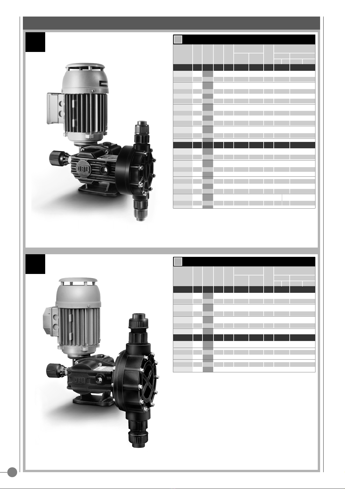
OBL MB Series User manual

SERIE
MB
MC
>OPERATING MANUAL
JOB N°
PUMP TYPE
SHEET
ELECTRIC ACTUATOR TYPE
OVERALL DRAWING 16
MB/MC 16
MB/MC Z-Z9 17
MECHANISM SECTIONAL DRAWINGS
18
PUMPHEAD SECTIONAL DRAWING
18
ENCLOSED
ITEM
SERIAL/No
GB
SERIES
MECHANICAL DIAPHRAGM
METERING PUMPS
SPRING RETURN
ENGLISH
:: M_
MB/MC
_GB_12.04 ::

1
2
3
4
5
6
PUMP CLEANING 1
TECHNICAL CHARACTERISTICS 2
MODEL NUMBER 3
1.1 - DESCRIPTION OF THE PUMP 4
1.2 - FLOW RATE 4
1.3 - MANUAL ADJUSTMENT 5
1.4 - MOTOR CHARACTERISTICS 5
1.5 - DIAPHRAGM STRUCTURE 5
2.1 - CORRECT INSTALLATION OF THE PUMP 6
2.2 - SUCTION LINE 6
2.3 - SUCTION SIDE FILTER 7
2.4 - SUCTION PIPING FOR VISCOUS LIQUIDS 8
2.5 - DISCHARGE LINE 8
2.6 - RELIEF VALVE 9
2.7 - INSTALLATION OF THE PULSATION DAMPER 9
2.8 - INSTALLATION OF THE PRESSURE GAUGE 10
2.9 - STANDARD PLANT ARRANGEMENT 10
2.10 -CASING OIL FILLING UP 10
3.1 - BEFORE STARTUP 11
3.2 - PUMP STARTUP 11
3.3 - POSSIBLE TROUBLES DURING STARTUP 12
4.1 - ROUTINE MAINTENANCE 13
4.2 - PREVENTIVE MAINTENANCE 14
4.3 - DISMANTLING (AND REASSEMBLY) 14
4.4 - OPERATING TROUBLES 15
5.1 - MB/5.2 -MC OVERALL DRAWINGS 16
5.3 - MB/MC Z-Z9 OVERALL DRAWINGS 17
MB/MC MECHANISM AND PUMPHEAD
SECTIONAL DRAWING 18
GENERAL SAFETY NORMS 20
DECLARATION OF CONFORMITY 21
GENERAL CHARACTERISTICS
INSTALLATION
STARTUP
MAINTENANCE
OVERALL DRAWINGS
SECTIONAL DRAWINGS
THE MACHINE DIRECTIVE
DECLARATION OF CONFORMITY
INDEX

1
1
2
4
3
A
B
SUCTION SIDE
Please be reminded to collect cleaning water in
specific containers. Containers to be collected
by authorised companies for the disposal of
waste waters.
- Pump to be
packed into palleti-
sed crate; pump to
be nailed to the
base in the vertical
position.
-
The cleaning procedure must be repeated for at
least 5 minutes.
-
Continue cleaning through
discharge port, maintaining
the connections horizontal.
SUCTION SIDE
-
Flush with water through the pump suction port
(motor opposite side).
-
Operator to be at least 2 metres away from pump.
-
Place the pump on
the floor, in a suita-
ble area for waste
water collection,
with the inlet and
outlet ports horizon-
tal.
A - Close terminal box cover and seal cable entry with PG plugs.
B- If there are no PG plugs available, the terminal box must be sealed
with adhesive waterproof tape.
-Sostituire il “TAPPO CON FORO” con il “TAPPO CIECO” fornito in dota-
zione con la pompa.
Pumps to be sent with cleanness certificate, so free from
any chemical trace into liquid end and all wetted parts.
If not supplied, pump (s) will be rejected and
sent back at customer’s charges.
MANDATORY REQUIREMENT
Basic suggestion for pump cleaning
C A U T I O N !
OBL s.r.l. welcome pumps despatched to our premises for servicing.
INFORMATION FOR CUSTOMERS

2
MB
MC
50 Hz
50 Hz
60 Hz
60 Hz
➜➜
TYPE
STROKES/1’
MAX FLOW
RATE l/h
Ø
DIAPHRAGM
STROKE
MAX PRESS.
BAR
TYPE
STROKES/1’
MAX FLOW
RATE l/h
Ø
DIAPHRAGM
STROKE
MAX PRESS.
BAR
CONNECTIONS
THREADED FLANGED
PP A PP A
VALVE
A P
TECHNICAL DATA
TECHNICAL DATA
CONNECTIONS
THREADED FLANGED
PP A PP A
VALVE
A P
MECHANICAL DIAPHRAGM METERING PUMPS
MB.11 36 11 94 2 CML 5 VP 7 12
3/8” BSPF
DN15
1/2”ANSI 150#RF
MB.16 50 16 94 2 CML 5 VP 7 12
3/8” BSPF
DN15
1/2”ANSI 150#RF
MB.23 70 23 94 2 CM 7 VP 7 12
3/8” BSPF
DN15
1/2”ANSI 150#RF
MB.31 95 31 94 2 CM 7 VP 7 8
3/8” BSPF
DN15
1/2”ANSI 150#RF
MB.37 115 37 94 2 CM 7 VP 7 8
3/8” BSPF
DN15
1/2”ANSI 150#RF
MB.50 155 50 94 2 CM 7 VP 7 8
3/8” BSPF
DN15
1/2”ANSI 150#RF
MB.35 36 35 108 4 CM 8
VP 8,5
6
3/8” BSPF
DN15
1/2”ANSI 150#RF
MB.49 50 49 108 4 CM 8
VP 8,5
6
3/8” BSPF
DN15
1/2”ANSI 150#RF
MB.75 70 75 108 4 CM 8
VP 8,5
6
3/8” BSPF
DN15
1/2”ANSI 150#RF
MB.101 95 101 108 4 CM 8
VP 8,5
6
3/8” BSPF
DN15
1/2”ANSI 150#RF
MB.120 115 120 108 4 CM 9
VP 8,5
6
3/8” BSPF
DN15
1/2”ANSI 150#RF
MB.155 155 155 108 4 CM 9
VP 8,5
6
3/8” BSPF
DN15
1/2”ANSI 150#RF
MB.9 30 994 2 CML 5 VP 7 12
3/8” BSPF
DN15
1/2”ANSI 150#RF
MB.14 43 14 94 2 CML 5 VP 7 12
3/8” BSPF
DN15
1/2”ANSI 150#RF
MB.28 84 28 94 2 CM 7 VP 7 12
3/8” BSPF
DN15
1/2”ANSI 150#RF
MB.36 114 36 94 2 CM 7 VP 7 8
3/8” BSPF
DN15
1/2”ANSI 150#RF
MB.45 138 45 94 2 CM 7 VP 7 8
3/8” BSPF
DN15
1/2”ANSI 150#RF
MB.42 43 42 108 4 CM 8
VP 8,5
6
3/8” BSPF
DN15
1/2”ANSI 150#RF
MB.58 60 58 108 4 CM 8
VP 8,5
6
3/8” BSPF
DN15
1/2”ANSI 150#RF
MB.90 84 90 108 4 CM 8
VP 8,5
6
3/8” BSPF
DN15
1/2”ANSI 150#RF
MB.121 115 121 108 4 CM 9
VP 8,5
6
3/8” 1/2”
DN15
1/2”ANSI 150#RF
MB.145 138 145 108 4 CM 9
VP 8,5
6
3/8” 1/2”
DN15
1/2”ANSI 150#RF
MC.101 36 100 138 6
CM 13,5 VP 11 G
7
3/4” BSPF
DN20
3/4”ANSI 150#RF
MC.131 50 132 138 6
CM 13,5 VP 11 G
7
3/4” BSPF
DN20
3/4”ANSI 150#RF
MC.201 70 197 138 6
CM 13,5 VP 13,5
7
3/4” BSPF
DN20
3/4”ANSI 150#RF
MC.261 95 260 138 6
CM 13,5 VP 13,5
7
3/4” BSPF
DN20
3/4”ANSI 150#RF
MC.321 115 320 138 6
VM 16,5 VP 17
5
1”
BSPF
DN25
3/4”ANSI 150#RF
MC.421 155 420 138 6
VM 16,5 VP 17
5
1”
BSPF
DN25
3/4”ANSI 150#RF
MC.120 43 120 138 6
CM 13,5 VP 11 G
7
3/4” BSPF
DN20
3/4”ANSI 150#RF
MC.158 60 158 138 6
CM 13,5 VP 13,5
7
3/4” BSPF
DN20
3/4”ANSI 150#RF
MC.236 84 236 138 6
CM 13,5 VP 13,5
7
3/4” BSPF
DN20
3/4”ANSI 150#RF
MC.312 114 312 138 6
VM 16,5 VP 17
5
1”
BSPF
DN25
1”ANSI 150#RF
MC.384 138 384 138 6
VM 16,5 VP 17
5
1”
BSPF
DN25
1”ANSI 150#RF

3
MB MC
PP PP11 PP32 A
➜
MB 37 PP F Z
➜
PARTS
MODEL NUMBERMATERIALS OF CONSTRUCTION
KEY TO SYMBOLS
PUPM TYPE
FLOW RATE l/h
PP PP CONSTRUCTION
A AISI-316L CONSTRUCTION
PP11 PP CONSTRUCTION+AISI-316L VALVE AND SEAT
PP32 PP CONSTRUCTION + HASTELLOY C VALVE - INCOLOY 825 SEAT
Z OBL ELECTRIC ACTUATOR
W 3÷15 PSI PNEUMATIC ACTUATOR
F UNI-DIN FLANGED CONNECTIONS
FA ANSI FLANGED CONNECTIONS
LIQUID END PP PP PP AISI 316L
VALVE GUIDE
POLYTHENE/PVC POLYTHENE/PVC POLYTHENE/PVC
AISI 316L
VALVE SEAT PVC AISI 316L
INCOLOY 825
AISI 316L
VALVE PIREX AISI 316L
HASTELLOY C-276
AISI 316L
VALVE SEAL
VITON (FPM) VITON (FPM) VITON (FPM) VITON (FPM)
VALVE HOUSING PP PP PP AISI 316L
DIAPHRAGM
TEFLON (PTFE) TEFLON (PTFE) TEFLON (PTFE) TEFLON (PTFE)

1.1
1
4
1
0° 180° 360°
1.2
Fig. 2
Theoretical flow rate
The theoretical flow rate
corresponds exactly to
the volume displaced by
the diaphragm during
its motion. Its graphic
representation is a dia-
gonal straight line
whose progression is
determined by the
diaphragm stroke increasing (fig.3).
Actual flow rate
The actual flow rate is inevi-
tably less than the theoreti-
cal flow rate because of the
losses due to the reaction
time of the valves. The ratio
between these two flow
rates determines the volu-
metric efficiency of the
pump. The efficiency
depends on pump size, pump head type (plunger or diaphragm), liquid
to be pumped, viscosity of the liquid, working
pressure, etc.
(fig. 4).
0° 50° 100°
10
5
0° 50° 100°
10
5
FLOW RATE
ACFLOWRATE
TH.FOLW RATE
TH.FOLW RATE
FLOW RATE
CLOSED
OPEN
OPEN
CLOSED
DISCHARGE STAGESUCTION STAGE
2°COMPLETE CYCLE
1° COMPLETE CYCLE
SUCTION
FLOW RATE
PER HOUR
SNAPSHOT
FLOW RATE
•The reciprocating motion of the diaphragm determines the flow thanks to the inlet and outlet check valves of the pump head
(fig. 2).
During the suction stage the inlet valve opens because of the depression created by the diaphragm while the outlet valve remains clo-
sed. The product enters the pump head and goes out throught the outlet valve when pushed by the diaphragm during the discharge
stage.
FLOW RATE
THE FLOW RATE LINEARITY
The operating of an OBL mecha-
nical diaphragm reflects the flow
rate linearity of a plunger pump.
This is proved by the graph here
on the left that evidences the
linear proportionality between
flow rate and adjustment per-
centage.
200
150
100
50
025% 50% 75% 100%
Adjustment %
Flow rate l/h
Table A
•The OBL’s metering pumps “MB/MC” series are con-
trolled-volume reciprocating pumps.
The crank gear is driven by an electric motor and the
strokes per minute of the diaphragm are given by an
integral, oil-splash-lubricated , endless
screw/wormwheel reduction gear (fig.1).
In MB/MC’s mechanical diaphragm metering pumps,
suction stage (diaphragm backward stroke) is by spring
return.
The MB/MC series metering pumps are characterised by
a so called mechanical diaphragm, where the reciproca-
ting movement is transmitted directly by the crank gear.
The mechanical diaphragm works, both giving the swept
volume, acting basically as plunger, and as separator between crank
gear and the handled fluid.
•The MB/MC mechanical diaphragm metering pumps give a double
advantage:
- Leak-free head.
- No plunger packing and related wearing problems.
These results are achieved thanks to the unique structure of the diaph-
ragm (patented), which bears the whole thrust of the handled liquid,
and, like a plunger pump, guarantees a linear flow rate (table A).
DESCRIPTION OF THE PUMP
GENERAL CHARACTERISTICS
Fig. 1

1
5
1.3
1.4
1.5
STANDARD
Fig. 5
DETAIL OF THE BONDING BETWEEN DIAPHRAGM AND METALLIC SUPPORT
DIAPHRAGM SECTIONAL VIEW
RUBBER
METALLIC
SUPPORT PFTE
RUBBER
PFTE
NYLON NET
Sectional view without
plastic support ring. Complete sectional view with
plastic support ring.
GAMAR MOTOR SPECIAL FLANGE AND SHAFT
PUMP TYPE PHASES kW POLES
SIZE
VOLT Hz
MB THREEPH 0,20 4 63 230 50/60
400
MC THREEPH 0,30 4 63 230 50/60
400
0,24/037 4 63/71 230 50
MB
SINGLEPH
0,24/037 4 63/71 230 60
MC 0,24/037 4 63/71 110 50
0,24/037 4 63/71 110 60
Table B
•The OBL's unique (patented) mechanical diaphragm
design ensures controlled volumetric displacement, giving
plunger-like performances.
Thus the flow rate is virtually unaffected by the working
pressure variations.
DIAPHRAGM STRUCTURE
•In table Bare described motors installed on MB/MC pumps.
Endless screw is directly keyed on extended motor shaft.
MOTOR CHARACTERISTICS ACCORDING TO THE PUMP SIZE
•The adjustment of the diaphragm stroke is stepless and regular, and can be
carried out any time, i.e. when the pump stands still or is running (fig.5).
FLOW RATE MANUAL BY MICROMETER
GENERAL CHARACTERISTICS
MANUAL ADJUSTMENT

2
6
2.1
2.2
80 cm. 70 cm.
0÷15 4x6 - - -
0÷30 6x10 - 1/4"-
0÷125 -
DN 10
3/8" Ø16
0÷155 -
DN 15
1/2" Ø20
1/2" ANSI
0÷260 -
DN 20
3/4" Ø25
3/4" ANSI
0÷420 -
DN 25
1" Ø32
1" ANSI
➜
➜
2
Fig. 7/A
Fig. 6
RIGHTWRONG
FILTER FOOT VALVE
Right
Right
Right
Pipe size according
with table C
Wrong
Risk of clogging of pump valves
Wrong
In the highest point of the piping
the fluid vein breaks
Wrong
Pipe size not according
with table C
•A proper installation and sizing of the suction line are of particular importance for a correct operation of the pump, the following
factors shall be taken into account
:
A) Pipe inner diameter
The pipe internal diameter will be chosen according to the pump flow rate (see table C)
.
The pump connections are oversized, in order to cover all applications.
B) Length of the piping
Suction piping is to be as short as possible, following the indications of table C
it is suggested:
- Max suction lift 1,5 metres
- Total length 2,5 metres (upright plus horizontal)
C) Arrangement of the suction line
For the arrangement of the suction line see Fig. 7/A and 7/B.
Table C
Relationship between flow rate and pipe size
FLOW RATE L/h
PIPE WITH
FITTINGS FLANGED
PIPE THREADED
PIPE PVC GLUED
PIPE
SUCTION LINE
ADJUSTMENT SIDE
HYDRAULIC SIDE
ASSEMBLING AREA
•Provide with adequate clearance areas and safe access for operation and mainte-
nance, in particular in front of the hydraulic side and of the adjustment knob (fig. 6).
•If the pump is installed outdoors, a shelter is recommend, specially when the pump is
equipped with electric actuators or other delicate devices.
•PP pump heads can work properly only at ambient temperature and metered liquid
temperatures below 40°C.
•If necessary, provide suitable protection from sun rays and check the temperature of
the metered liquid.
INSTRUCTIONS FOR A PROPER INSTALLATION
INSTALLATION
INSTALLATION

2
7
➜
➜
➜
➜
2.3
1÷15 40
15÷50 40
100÷200 30
200÷420 30
Fig. 8
Fig. 7/B
NO
NO
•
The installation of a filter on the suction side is always recommended, particularly when the liquid to be metered contains suspended particles.
•The characteristics of the filter net depend on the kind of liquid and pump flow rate.
For liquids with viscosity not exceeding 200 cp see table D.
•To prevent sucking of impurities, specially when liquids with solid content are
metered, the suction pipe shall not draw the liquid from the bottom of the tank.
The suction point should be 10 cm from the tank bottom (fig.8).
Examples of installation of the filter
Flow rate L/h Mesch
Table D
CAUTION! A small-sized filter will affect the metering performances.
Use Y- filters with a size larger than the suction connection.
RIGHTWRONG
Wrong
Wrong
Right
Right
SUCTION SIDE FILTER
INSTALLATION
Right
Right
Right
Suggested installation
Acceptable installation
Wrong
Irregular suction
Wrong
Wrong
Wrong
RIGHTWRONG

2
8
➜
➜
➜
➜
2.4
2.5
36 2000
50 1500
70 800
95 400
115 300
155 100
Fig. 9
Fig. 10
RIGHTWRONG
INJECTION
NOZZLE
BACKPRESSURE
VALVE
Right
Right
Wrong
Siphoning.
Uncontrollable flow rate
.
Wrong
Failing a back pressure valve, the
flow in pipeline “A” draws the
product from the tank in an
uncontrolled way.
•When the free surface of the liquid in the suction side tank is above discharge-side tank level, an uncontrollable flow from the suction
side tank to the discharge side tank will occur.
•To prevent this natural passage of liquid, the discharge pressure must always be at least 0,3 Kg/cmq, higher than the suction pres-
sure, in case of small flow rates 0,5 Kg/cmq.
•If for any reason this condition cannot be complied with the plant it is necessary to create a backpressure by means of a suitable
valve, or better to highten the discharge pipe so as to prevent the siphoning effect (fig.10).
DISCHARGE LINE
RIGHTWRONG
Recommended
Recommended
Right
Wrong
Wrong
Wrong
S.P.M. cp max execution "A"
Table E
Relationship between strokes per minute "SPM" and
viscosity of the liquid "cp", valid for AISI 316L or PP.11
pump heads.
•Specific technical information is required for the installation of pumps intended for
metering viscous liquids.
- For this kind of application we recommend stainless steel pumpheads.
- The suction piping must have an adequate diameter; as a rule, for high-viscosity liq-
uids (2000 cps), select the size immediately above the diameter of the pump suction
connections.
- In any case, when viscous liquids are to be metered choose for the pipe at least the
same size as that of the pump connections.
Examples of installation for viscous liquids
INSTALLATION
SUCTION PIPING FOR VISCOUS LIQUIDS

2
9
2.6
2.7
Fig. 11
Fig. 12
Bladder type dampener
• The liquid is separed from the relieving chamber by a diaphragm.
• Dampener volume: about 8 times the pump swept volume.
Advantages:
• Small volume.
•
No need for periodic inflation because the gas is contained in the bladder.
Disadvantages:
• It is necessary to know prior the exact working pressure in order to
determine the damper precharge.
Dampener types
Bottle dampener
•
Is made up of a cylindrical-shape barrel developed in its height.
• Dampener volume: about 35 times the pump swept volume
.
Advantages:
• It does not need precharge because is self-running.
Disadvantages:
• It has to be regenerated periodically by releasing the liquid
through the drain valve in order to restore the air absorbed by
the liquid.
DAMPENER
DRAIN VALVE
DAMPENER
DRAIN VALVE
SPRAY
NOZZLE
PRESSURE GAUGE
(ABSOLUTELY
NECESSARY)
BACKPRESSURE
VALVE
DAMPENER
DRAIN VALVE
DAMPENER
DRAIN VALVE
Flow rate diaphragm
(with dampener)
Installation with working
pressure lower 1 bar
Spray nozzle
installation
Flow rate diaphragm
(without dampener)
Installation with working
pressure higher than 1 bar
Discharge line too long
and winding
• The pulsation dampener is decisive for a proper operation of the metering pumps.
The installation of a pulsation dampener offers several advantages because this device:
- Protetects the metering pump against pressure peaks, thus increasing the working of life of the pump.
- Prevents vibrations all along the discharge line.
- Smooth the flow, useful for the process.
• The pulsating flow, which is a negative characteristic of all metering pumps, can therefore be prevented by installing a pulsation
dampener on the discharge line (fig. 12).
Examples of installation of the pulsation dampener
INSTALLATION OF THE PULSATION DAMPENER
CAUTION ! Mechanical diaphragm metering pumps absolutely need the
installation of a relief valve; a pressure higher than the rating plate value would
break the mechanism.
•The safety valve has to be installed immediately after the discharge connection, anyhow
before the on-off valve.
•The relief valve setting (set pressure) must not exceed the pump max. pressure value.
•The safety valve protects the pump from:
Excessive pressure(pressure higher than the rated value).
Operator mistakes (E.G., on-off valve closed on the discharge line when the pump is running).
Obstruction of the discharge piping (reduction in section clogging).
•A relief valve is absolutely necessary when an on-off valve is fitted on the discharge line (fig.11).
The installation of a safety valve is always essential both because of the above reasons and for the safety regulation for accident at work.
SAFETY VALVE
ON OFF VALVE
SAFETY VALVE
INSTALLATION

2.8
2
10
2.9
2.
10
MB MC
ESSO SPARTAN EP 320
MOBIL MOBILGEAR 632
SHELL OMALA OIL 320
MB 0,4 L
MC 0,4 L
Fig. 13
Fig. 15
Fig. 14
PUMP OIL QUANTITY
BRAND TYPE
Table F
Pumps are always supplied
without oil.
For oil type see table F.
OIL WINDOW
OIL DRAIN
OIL FILLING UP
CRANK HOUSING OIL FILLING UP
• Unscrew the filling plug located on the
crank housing and pour lubricating oil
into it.
1 - "Y" filter
2 - Metering pump
3 - Safety valve
4 - Drain valve
5 - On-off valve
6 - Pulsation dampener
7 - Pressure gauge
• Figure 14 shows the indications for a correct installation of the metering pumps.
STANDARD PLANT ARRANGEMENT
DRAIN VALVE
SAFETY VALVE
PRESSURE GAUGE
• In order to check if the metering pump operates correctly, it is essential to install a pres-
sure gauge on the discharge line (fig. 13).
• The pressure gauge shows the actual working pressure of the metering pump. This
value must not exceed the max. allowed pressure of the pump.
INSTALLATION OF THE PRESSURE GAUGE
INSTALLATION

3
11
3.1
3
3.2
CAUTION !
THE PUMP CANNOT STAND PRESSURES HIGHER THAN THOSE INDICATED ON THE RATING PLATE.
•With pump not running, check the oil through the oil window (for oil type see table F).
• Check the electric connections and also the direction of rotation of the motor (shown by the arrow on motor body).
•Make sure that all on-off valves on the suction and discharge pipelines are open.
• Make sure that the liquid to be metered has not solidified or frozen inside the piping.
• Carry out the first startup with discharge pressure as low as possible and with adjustment knob set to 20%; keep these conditions
about 3 ÷ 5 minutes. Increase gradually the flow rate up to the maximum value, then set the pump to the required working conditions
(flow rate and pressure).
• During the first stage check the pump discharge pressure by means of the pressure gauge: the pressure value (max. oscillation of the
pointer) must not exceed the max. pressure indicated on the pump rating plate.
THE STARTUP HAS TO BE DONE AS FOLLOWS:
STARTUP
• Make sure that the baseplate is made of steel, stable and even. Do not install the pump directly on a concrete foundation.
• Fix the pump to the baseplate using the specific anchor holes in the pump feet.
• Make sure that the pump valve axis is perfectly upright.
• Before connecting the piping to the pump, it is absolutely necessary to flush the pipelines with water, especially the suction line and
relevant feed tank.
• The pipelines must be independently supported, so as to prevent stresses on the pumphead. Therefore, besides the baseplate, the
pump needs a supporting framework for both suction and discharge pipelines.
• It is recommended to fit a cross after the discharge flange. This fitting will facilitate the removal of the pump from the baseplate and
can be used for the installation of pressure gauges, safety valves and dampeners.
• Make sure that the pipeline fittings and flanges are perfectly tight and in particular that no air enters the suction line, as this would
hinder the priming of the pump.
This preliminary flushing is often underestimated by the installator; if this operation is not
properly carried out, the pump will become a collector of all foreing matters contained in
the pipeline and tank, such as weld drops, gasket scraps, soil and other stuff.
BEFORE THE STARTUP VERIFY THE FOLLOWING CONDITIONS:
BEFORE THE STARTUP
STARTUP
STARTUP

3
12
3.3
➜
➜
➜
➜
• The suction hydrostatic head exceeds the discharge pressure: Increase the discharge pressure by means of a back
pressure valve. (OBL, series 300).
•
Back pressure valve stuck in open position because of foreing
matters, or pressure setting too low respect to the suction head:
Check
.
• Pump valves jammed in open position:
Check
.
SOLUTIONSCAUSES
SOLUTIONSCAUSES
STARTUP
FLOW RATE IRREGULAR OR HIGHER THAN EXPECTED
• Air entering the suction piping through the fittings:
Check.
• Air trapped inside the pump:
Raise pump flow rate to maximum value, otherwise unscrew
discharge valve housing (pos.14) till the liquid arrives.
• Suction lift too high:
Reduce it.
• The vapour pressure of the fluid is too high:
Increase the hydrostatic head on suction side.
• The viscosity of the liquid is too high:
Install a suction piping having a larger diameter.
Increase the hydrostatic head on suction side.
• Suction piping is clogged or its valves are shut:
Verify.
• Filter on suction side is clogged:
Clean it.
• Pump valves are stuck because of foreign matters
coming from suction side:
Dismantle the valves and clean them carefully.
• Check valves are mis-arranged:
See instructions on page 14
(Pump heads - Dismanting and reassembly ).
FLOW RATE LOWER THAN EXPECTED
POSSIBLE TROUBLES DURING STARTUP

4
13
4.1
4
15
5
15
5
15
5
15
5
Fig. 17
Fig. 16
AISI 316L head “A” execution, flanged connections.
AISI 316L head “A” execution, threaded connections.
PP head “PP” execution, flangeded connections.
PP head “PP” execution, threaded connections.
PROPER ARRANGEMENT OF:
-Valves pos. 15
-Seal pos. 5
• Refer first to the pumphead section
drawing.
• Pay attention to the arrangement of the
valve components; each valve ball rests by
gravity on its seat (Figure 17).
• Unscrew the suction and discharge valve
units, one at a time. Check their components
for soundness and cleanness.
• Clean carefully all valve components: seat,
ball, guide, housing.
In case of lower or irregular flow rate,
check the valve units as follows
:
MAINTENANCE
MAINTENANCE
ROUTINE MAINTENANCE
OIL DRAINING
OIL WINDOW
OIL FILLING UP
• Check the oil level periodically
(fig. 16)
.
• Change the oil every 10.000 operating hours.

4
14
4.2
4.3
32
29
15
14
21
102
Fig. 18
A)
• Unscrew valve housing (pos.14).
• Take note of the arrangement of the various components of the
valve unit.
• Extract the valves.
• Clean carefully their seat.
• If necessary, replace seats and valves.
• Reassemble valve unit exactly as before noted.
• Screw back valve housing (pos.14)
B)
• Diaphragm (pos. 32)
• Take off pump head screws (pos. 29).
• Remove pump head (pos.21).
• Unscrew the diaphragm (pos.32) by turning it counterclockwise.
• Before screwing up the diaphragm, grease its thread (pos.102)
(threaded top end of the slide).
• Screw up the diaphragm and make sure that it reaches its end
position.
• Re-assemble the pump head (pos. 21), checking valves groupes
arrangement.
• Gradually screw back in pos. 29 (screws).
Do not overtighten: - for MB type max 3,5 Nm
Do not overtighten:- for MC type max 5 Nm.
• Valves (pos. 15).
To dismantle the valves it is necessary to unscrew, first the valve housing (pos.14) and take off the valve balls.
Assuming that cleaning of the valves is required, proceed as follows on the valve units one at a time:
DIAPHRAGM 32 1 32 1
VALVE SEATS 5 2 5 2
VALVE GUIDES
6262
VALVE
15 2 15 2
8282
VALVE SEAL
9292
76
EXECUTION (HEAD BODY MATERIAL)
DENOMINATION
PP A AISI 316L
POSITION
PIECES NO.
POSITION
PIECES NO.
Table G
DISMANTING ( AND REASSEMBLY )
MAINTENANCE
• We suggest the purchasing of a series of essential details
for the preventive maintenance of diaphragm pump head
(table G).
For the positions see pump head sectional drawing.
PREVENTIVE MAINTENANCE

4
15
4.4
➜
➜
➜
➜
➜
➜
SOLUTIONSCAUSES
• Incorrect wiring: Check.
•
Overheating due to pump working pressure higher than allowed:
Check max. discharge pressure by means of a pressure gauge
fitted on the discharge pipeline.
• Pressures higher than allowed: (see max. pressure indicated on pump rating plate) reduce the
discharge pressure or install a dampener in case of excessive
narrowing on the discharge pipeline.
• Stresses on pump flanges: Loosen the pipes connected to the pumphead
and check.
• Discharge pipeline clogged or valve shut: Check.
• Back pressure valve set to a pressure higher Check.
than allowed:
• Oil level in the gearbox is low: Add suitable oil. See table F, page 10.
OVERHEATING OF PUMP BODY AND MOTOR
MAINTENANCE
SOLUTIONSCAUSES
SOLUTIONSCAUSES
• Air enters the suction piping through the fittings:
Check.
• Air trapped inside the pump:
For a short while, keep flow rate to maximum
.
• Excessive suction head lift:
Reduce it.
• Vapour pressure of the liquid too high:
Increase hydrostatic head on suction side.
• Pumping temperatures too high:
Increase hydrostatic head on suction side.
• Viscosity of the liquid too high:
Install a suction piping of larger diameter. Increase hydrostatic
head on suction side.
• Feed tank hermetically sealed and with no vent:
Make a vent in the tank upper part.
• Suction piping clogged or valves shut
Check.
• Filter on suction side clogged:
Clean it.
• Pump valves jammed because of dirt:
Dismantle the valves and clean them carefully.
• Safety valve setting pressure too low:
Check.
• Suction pressure higher than discharge pressure: Increase the discharge head of at least 0,3÷0,5 Kg/cmq
(3÷5m) respect to the suction pressure.
• Back pressure valve stuck in open position because of dirt
or setting pressure too low: Check.
• Pump valves jammed in open position: Check.
FLOW RATE IRREGULAR OR HIGHER THAN EXPECTED
FLOW RATE LOWER THAN EXPECTED
OPERATING TROUBLES

MB
MC
5
16
5
AISI 316 L PP DN
ABCg.f.ETØA BCg.f. ETØ
UNI ANSI
AISI 316 L PP DN
ABCg.f.ETØA BCg.f. ETØ
UNI ANSI
Adjustment:
With 0 -10 scale micrometer knob
Flow rates:
●
100÷420 L/h (stroke 6mm.)
Motors: ● Threephase 0,30 kW - 230/400 V - 50/60 Hz
4
poles -
IP55 - CL F - IEC34-1 Special flange motor
● Singlephase 0,24/0,37 kW - 230 V - 50/60 Hz
4
poles -
IP55 - CL F - IEC34-1 Special flange motor
Material:
•Aluminium casing
•Pump head: PP (Polipropilene)
A(AISI 316L)
Weigth: •12 Kgs
TYPE
FLANGED
CONNECTIONS
THREADED
CONNECTIONS
N° 2 HOLES Ø9
TYPE
FLANGED
CONNECTIONS
THREADED
CONNECTIONS
N° 2 HOLES Ø9
Adjustment:
With 0 -10 scale micrometer knob
Flow rates:
●
11÷50 L/h (stroke 2mm.)
●
35÷155 L/h (stroke 4mm.)
Motors: ● Threephase 0,20 kW - 230/400 V - 50/60 Hz
4
poles -
IP55 - CL F - IEC34-1 Special flange motor
● Singlephase 0,24/0,37 kW - 230 V - 50/60 Hz
4
poles -
IP55 - CL F - IEC34-1 Special flange motor
Material:
•Aluminium casing
•Pump head: PP (Polipropilene)
A(AISI 316L)
Weigth: •10 Kgs
PUMP OVERALL DRAWINGS
OVERALL DRAWINGS
MB 11 166 132,5
3/8” BSPF
180 114 237 133
3/8” BSPF
201 117 15 1/2”
MB 16 166 132,5
3/8” BSPF
180 114 237 133
3/8” BSPF
201 117 15 1/2”
MB 23 166 132,5
3/8” BSPF
180 114 237 133
3/8” BSPF
201 117 15 1/2”
MB 31 166 132,5
3/8” BSPF
180 114 237 133
3/8” BSPF
201 117 15 1/2”
MB 37 166 132,5
3/8” BSPF
180 114 237 133
3/8” BSPF
201 117 15 1/2”
MB 50 166 132,5
3/8” BSPF
180 114 237 133
3/8” BSPF
201 117 15 1/2”
MB 35 181 132
3/8” BSPF
195 129 251 133
3/8” BSPF
215 133 15 1/2”
MB 49 181 132
3/8” BSPF
195 129 251 133
3/8” BSPF
215 133 15 1/2”
MB 75 181 132
3/8” BSPF
195 129 251 133
3/8” BSPF
215 133 15 1/2”
MB 101 181 132
3/8” BSPF
195 129 251 133
3/8” BSPF
215 133 15 1/2”
MB 120 200 133,5
1/2” BSPF
200 129 251 133
3/8” BSPF
215 133 15 1/2”
MB 155 200 133,5
1/2” BSPF
200 129 251 133
3/8” BSPF
215 133 15 1/2”
MC 101
235 142
3/4” BSPF
235 159 347 145
3/4” BSPF
303 162 20 3/4”
MC 131
235 142
3/4” BSPF
235 159 347 145
3/4” BSPF
303 162 20 3/4”
MC 201
235 142
3/4” BSPF
235 159 347 145
3/4” BSPF
303 162 20 3/4”
MC 261
235 142
3/4” BSPF
235 159 347 145
3/4” BSPF
303 162 20 3/4”
MC 321
276 140
1” BSPF
261 159 355 145
1” BSPF
303 162 25 1”
MC 421
276 140
1” BSPF
261 159 355 145
1” BSPF
303 162 25 1”

5
17
MB MC
Z9
MB MC
Z
ADJUSTMENT READING
ADJUSTMENT READING
MANUAL ADJUSTMENT
OVERALL DRAWINGS
PUMP WITH ELECTRIC ADJUSTMENT OVERALL DRAWINGS
Motors: •Threephase 0,20/0,30 kW - 230/400 V
50/60 Hz - 4 Poles - IP55 - CL F - IEC34-1
Special flange motor
•Singlephase 0,24/0,37 kW - 230 V - 50/60 Hz
4 Poles - IP55 - CL F - IEC34-1
Special flange motor
Material: •Aluminium casing
•Pump head: PP (Polipropilene)
A(AISI 316L)
Weigth: •20÷35 Kgs
Motors: •Threephase 0,20/0,30 kW - 230/400 V
50/60 Hz - 4 Poles - IP55 - CL F - IEC34-1
Special flange motor
•Singlephase 0,24/37 kW
230 V - 50/60 Hz - 4 Poles
IP55 - CL F - IEC34-1
Special flange motor
Material: •Aluminium casing
•Pump head: PP (Polipropilene)
A(AISI 316L)
Weigth: •20÷35 Kgs
FLANGED
CONNECT.
THREADED
CONNECT.
FLANGED
CONNECT.
THREADED
CONNECT.

6
18
MB MC
PP11
- SEAT: AISI 316 L
- BALL: AISI 316 L
PP32
- SEAT: INCOLOY 825
-
BALL:
HASTELLOY C-276
Head Construction PP11
Head Construction PP
Pumphead sectional drawings
MECHANISM
MECHANISM SECTIONAL DRAWING
Other manuals for MB Series
2
This manual suits for next models
34
Table of contents
Other OBL Water Pump manuals
Popular Water Pump manuals by other brands

Lutz-Jesco
Lutz-Jesco MEMDOS SMART LK operating instructions

Alemlube
Alemlube P50 Owner technical manual

Xylem
Xylem Flygt 5520 Installation, operation and maintenance manual

AES
AES MINI FOUL Installation, Operating, Maintenance

MYERS
MYERS DE Series owner's manual

Spirax Sarco
Spirax Sarco APT10-2 Installation and maintenance instructions