OBL PRO Series User manual

CONTROL AND MANAGEMENT KIT FOR
METERING PUMPS
KIT-PRO /KIT-PRO UL
Doc. No.
UT-5601
Rev.
3
Lang.
EN
1st Issue
24/06/2020
Prepared by
A.A.
Checked by
C.V.C.
Replaced on
USE AND MAINTENANCE MANUAL
SERIES
PRO
EN

File: UT-5601 Copyright © - OBL Metering pumps - All rights reserved
1
REVISION INDEX
Chapters
Rev
Date
Rev
Date
Rev
Date
Rev
Date
Index
0
20/06/2018
1
05/10/2018
2
07/02/2019
3
24/06/2020
0
0
20/06/2018
2
07/02/2019
1
0
20/06/2018
2
07/02/2019
3
24/06/2020
2
0
20/06/2018
3
24/06/2020
3
0
20/06/2018
2
07/02/2019
3
24/06/2020
4
0
20/06/2018
1
05/10/2018
3
24/06/2020
5
0
20/06/2018
1
05/10/2018
3
24/06/2020
6
0
20/06/2018
3
24/06/2020
7
0
20/06/2018
3
24/06/2020
8
0
20/06/2018
3
24/06/2020
Date
24/06/2020
Signature

File: UT-5601 Copyright © - OBL Metering pumps - All rights reserved
2
TABLE OF CONTENTS
REVISION INDEX ------------------------------------------------------------------------------------------------1
TABLE OF CONTENTS-------------------------------------------------------------------------------------------2
0INTRODUCTION -------------------------------------------------------------------------------------------------------------------3
1SCOPE OF THE USE AND MAINTENANCE MANUAL ---------------------------------------------------3
2HOW TO READ THIS USER MANUAL --------------------------------------------------------------------3
1GENERAL INFORMATION -------------------------------------------------------------------------------------------------------4
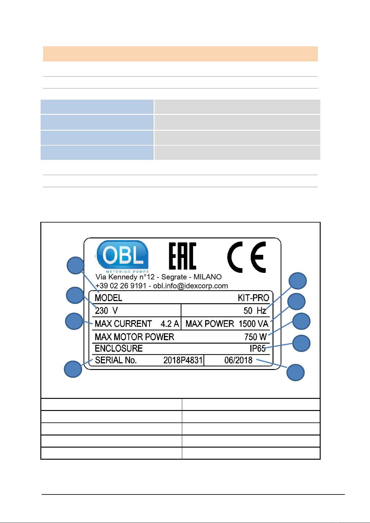
1MANUFACTURER’S IDENTIFICATION DATA -----------------------------------------------------------4
2CE MARKING------------------------------------------------------------------------------------------------4
3UL MARKING------------------------------------------------------------------------------------------------5
4DECLARATIONS --------------------------------------------------------------------------------------------6
5UL CERTIFICATION----------------------------------------------------------------------------------------7
6TECHNICAL SUPPORT -INFORMATION ----------------------------------------------------------------8
2SAFETY -------------------------------------------------------------------------------------------------------------------------------8
1GENERAL SAFETY WARNINGS ---------------------------------------------------------------------------8
2USE RESTRICTIONS ---------------------------------------------------------------------------------------8
3ELECTROMAGNETIC COMPATIBILITY ------------------------------------------------------------------8
4SAFETY ------------------------------------------------------------------------------------------------------9
5SAFETY PICTOGRAMS-------------------------------------------------------------------------------------9
3INSTALLATION ------------------------------------------------------------------------------------------------------------------- 10
1TRANSPORT AND HANDLING -------------------------------------------------------------------------- 10
2STORAGE CONDITIONS -------------------------------------------------------------------------------- 10
3POSITIONING -------------------------------------------------------------------------------------------- 11
4ADJUSTMENTS ------------------------------------------------------------------------------------------- 11
5ASSEMBLY ------------------------------------------------------------------------------------------------ 12
6ELECTRICAL CONNECTIONS --------------------------------------------------------------------------- 13
4PRODUCT DESCRIPTION ------------------------------------------------------------------------------------------------------ 15
1OPERATING PRINCIPLE--------------------------------------------------------------------------------- 15
2MAIN COMPONENTS AND DIMENSIONS ------------------------------------------------------------- 16
3ENVIRONMENTAL CONDITIONS ---------------------------------------------------------------------- 18
4TECHNICAL DATA---------------------------------------------------------------------------------------- 19
5USE AND SOFTWARE ---------------------------------------------------------------------------------------------------------- 20
1INTERFACE ----------------------------------------------------------------------------------------------- 20
2ICONS ----------------------------------------------------------------------------------------------------- 20
3MENU ------------------------------------------------------------------------------------------------------ 21
6MAINTENANCE ------------------------------------------------------------------------------------------------------------------ 38
1ROUTINE MAINTENANCE------------------------------------------------------------------------------- 38
2TROUBLESHOOTING ------------------------------------------------------------------------------------ 39
7ACCESSORIES AND SPARE PARTS ------------------------------------------------------------------------------------------ 40
1ASSISTANCE---------------------------------------------------------------------------------------------- 40
2SPARE PARTS--------------------------------------------------------------------------------------------- 40
8ADDITIONAL INSTRUCTIONS ------------------------------------------------------------------------------------------------ 41
1DECOMMISSIONING AND DISASSEMBLY ------------------------------------------------------------ 41

File: UT-5601 Copyright © - OBL Metering pumps - All rights reserved
3
0INTRODUCTION
1SCOPE OF THE USE AND MAINTENANCE MANUAL
This manual provides the user with general guidelines to use the product safely.
This User Manual is an integral part of the product and provides the following information about
the product:
▪technical specifications;
▪a description of its operation and limits;
▪instructions on how to use it under safe conditions;
▪instructions on how to perform maintenance and repairs correctly and safely;
▪technical support;
▪instructions on waste disposal.
2HOW TO READ THIS USER MANUAL
This manual is divided into chapters. Each one of them provides specific information.
NUMBERING OF THE FIGURES
Each figure is numbered progressively.
NUMBERING OF THE TABLES
Each table is numbered progressively.
The progressive number starts from 1 at every new paragraph.
ABBREVIATIONS
Cap. = Chapter
Par. = Paragraph
Sec. = Section
Page = Page
Fig. = Figure
Tab. = Table

File: UT-5601 Copyright © - OBL Metering pumps - All rights reserved
4
1GENERAL INFORMATION
1MANUFACTURER’S IDENTIFICATION DATA
MANUFACTURER
OBL S.R.L.
REGISTERED HEADQUARTERS
AND ADMINISTRATIVE OFFICE
Via Kennedy 12 - 20090 Segrate (MILAN) ITALY
TELEPHONE NUMBER
0039 02 26 91 91
E-MAIL
2CE MARKING
Every KIT-PRO product is identified with a CE label indicating its reference data, which are printed
indelibly.
1=Product model
6=Protection rating
2=Power supply voltage
7=Serial number
3=Maximum current consumption
8=Month and year of manufacture
4=Power supply frequency
9=Max power of the motor
5=Maximum power consumption
1
2
3
7
4
5
6
8
9

File: UT-5601 Copyright © - OBL Metering pumps - All rights reserved
5
3UL MARKING
Every KIT-PRO UL product is identified with a UL label indicating its reference data, which are
printed indelibly.
1=Product model
4=NEMA type
2=Product input data
5=Manufacturing year and month
3=Product output data
6=Warnings
1
2
3
4
5
6

File: UT-5601 Copyright © - OBL Metering pumps - All rights reserved
6
4DECLARATIONS
EU DECLARATION OF CONFORMITY (UT5604-0)
(ANNEX IV, DIR. 2014/35/EU)
THE MANUFACTURER
COMPANY NAME
OBL SRL
ADDRESS
VIA KENNEDY 12, 20090 Segrate –MILAN - Italy
DECLARES THAT THE PRODUCT
NAME
MODEL
KIT PRO
KIT PRO
COMPLIES WITH THE FOLLOWING EUROPEAN DIRECTIVES
DIRECTIVE 2014/35/EU of the European Parliament and Council, dated 26 February 2014, on
the harmonisation of the laws of the Member States relating to the making available on the market
of electrical equipment designed for use within certain voltage limits
DIRECTIVE 2014/30/EU of the European Parliament and Council, dated 26 February 2014, on
the harmonisation of the laws of the Member States relating to electromagnetic compatibility
(recast)
AND THAT THE FOLLOWING STANDARDS HAVE BEEN APPLIED
(PARTS/ARTICLES OF HARMONISED STANDARDS)
EN 61800-5-1
Adjustable speed power drive systems - Part 5-1: Safety
provisions - Electric, thermal, and energy safety
DATE AND PLACE
SIGNATURE

File: UT-5601 Copyright © - OBL Metering pumps - All rights reserved
7
5UL CERTIFICATION

File: UT-5601 Copyright © - OBL Metering pumps - All rights reserved
8
6TECHNICAL SUPPORT - INFORMATION
This product is guaranteed as stated in the general terms and conditions of sale. Should
malfunctions or failures (included within the cases covered by the warranty) be detected during the
warranty period, the Manufacturer will repair or replace the defective parts, prior to
verification.SAFETY
2SAFETY
1GENERAL SAFETY WARNINGS
The Manufacturer has designed this product to make it as SAFE as possible.
Every OBL KIT PRO is a reliable, quality product, which undergoes careful end inspection to ensure
proper operation and ascertain compliance with specified performance.
The Manufacturer of the machine must install the product and comply with all the regulations and
safety standards in force in the country of installation.
Attention! When using mains-powered equipment, always follow basic safety precautions, including
the following, to reduce damage to people and property:
Carefully read the instructions in this manual before installing/using the device.
Keep these instructions for future use.
2USE RESTRICTIONS
The PRO KIT can be installed only and exclusively on the following pump models:
1. OBL’s metering pumps of the Black Line series (M diaphragm version)
2. OBL’s metering pumps of the Black Line series (R piston version)
3. OBL’s metering pumps of the Black Line series (XRN version)
3ELECTROMAGNETIC COMPATIBILITY
The user is the only responsible for solving problems related to electromagnetic compatibility once
the finished product is completely produced. In some cases, the equipment needs to be earthed
correctly, while in others a screen may be required. The manufacturer of the KIT PRO is available
to help the user solve problems related to electromagnetic compatibility upon request.

File: UT-5601 Copyright © - OBL Metering pumps - All rights reserved
9
4SAFETY
•Carefully read this use and maintenance manual before starting, using, performing
maintenance, or any other operation on the equipment.
•Strictly comply with the warnings contained in the manual, whether they indicate danger or
caution.
•The operator must meet all the requirements for using this type of machine.
•Always wear personal protective equipment in compliance with the occupational safety
regulations in force.
•Before proceeding with the installation, make sure that the area does not feature any
dangerous condition. Make sure no foreign bodies have been left inside or on the machine.
•Start the machine start-up sequence following the instructions.
•Do not enter the machine’s operating area while the machine is running.
•Do not introduce your hands or anything else near or inside the equipment live parts.
•Do not work in dark conditions. Use all the lights available, making sure they are efficient.
•Do not use the machine when under the influence of medicines or alcohol, as they may
impact your capacity of moving and thinking.
•Stay concentrated and use caution before carrying out any operation.
•Always keep the work area clean.
•Warn the maintenance managers about any malfunction of parts or systems on board the
machine.
•Do not wear loose clothing, but always accident-prevention clothing.
NOTE (for UL version):Integral solid state short circuit protection does not
provide branch circuit protection. Branch circuit protection must be provided in
accordance with the National Electrical Code and any additional local codes.
CSA: INTEGRAL SOLID STATE SHORT CIRCUIT PROTECTION DOES NOT
PROVIDE BRANCH CIRCUIT PROTECTION. BRANCH CIRCUIT PROTECTION
MUST BE PROVIDED IN ACCORDANCE WITH THE CANADIAN ELECTRICAL
CODE, PART I.
5SAFETY PICTOGRAMS
The device is installed on OBL metering pumps. Pay attention to the safety pictograms on the
pumps.

File: UT-5601 Copyright © - OBL Metering pumps - All rights reserved
10
3INSTALLATION
1TRANSPORT AND HANDLING
The KIT-PRO / KIT-PRO UL can be handled manually as it weighs only 5 kg. Always transport the
product inside its original packaging.
2STORAGE CONDITIONS
If not used immediately, the KIT-PRO/KIT-PRO UL should be stored with suitable covers in a
temperate, dry, clean, vibration-free and weatherproof environment. Protect from soil moisture by
placing the unit on shelves or wooden pallets. If the temperature is below 0°C, ensure that it does
not go lower than -10°C. If not specifically highlighted on the package, do not stack packaging, to
prevent damage to the KIT-PRO and to avoid tipping over or falling that can create accidents.
Ensure that access of unauthorized persons is not allowed in the storage location and that the floor
or shelf can support the weight of the machinery or equipment stored. Take additional safety
measures in the case of storage in extreme conditions, i.e. in sub-tropical or desert climates.
Report special storage conditions in advance in order to provide for adequate
packaging.
Check the dimensions and overall gross weight of the package before handling
or lifting it.

File: UT-5601 Copyright © - OBL Metering pumps - All rights reserved
11
3POSITIONING
The Black Line 2.0 M and R pumps can be installed on a KIT-PRO, as shown in Figure 1.
Figure 1 Installation of the KIT
Moreover, the orientation of KIT-PRO / KIT-PRO UL can be changed from 0 to 90° compared to the
pump. To carry out this operation, you just have to:
1. unscrew the 2 screws (M6x18)
2. rotate the pump
3. tighten the 2 screws (M6x18)
4ADJUSTMENTS
See chapter 5 “USE AND SOFTWARE”.

File: UT-5601 Copyright © - OBL Metering pumps - All rights reserved
12
5ASSEMBLY
The KIT PRO /KIT PRO UL can be supplied in two versions:
-Assembled on an OBL metering pump (Black Line series)
-The assembly kit can be assembled and installed on an OBL Black Line 2.0 metering pump
(manufactured from May 2017 onwards)
The KIT PRO must be assembled on pumps not installed in a system. Contact an OBL
distributor in the event the OBL pump on which the KIT PRO is to be installed is
already operating in a system.
The KIT PRO is suitable for all OBL metering pumps of the Black Line series with a
standard motor (three-phase power supply 380V/230V/110V 50/60 Hz). Contact an
OBL distributor in the event motors with different characteristics are installed.
Follow the instructions below to assemble the KIT PRO on OBL’s Black Line metering pumps:
1. Make sure the motor is not powered
2. Make sure that the OBL metering pump on which the KIT PRO is to be installed is not
running.
3. Disassemble the base of the Black Line pump (pos. 117 in the BL2.0 M and R section
drawings)
4. Mount connection P20.2189 (Figure 1) using the M6x25 screws.
5. Fasten the KIT PRO to the connection (Figure 1) using the provided M6x18 screws.
6. Disconnect any connection to the electric motor terminal box of the Black Line metering
pump.
7. Connect the KIT PRO’s output cable to the terminal box of the Black
Line pump’s motor, making sure that the connection is delta (230 V)
like the picture on the side. Refer to the use and maintenance manual
of the Black Line metering pump, chapter 2 paragraph 6, and chapter
8. In the following table please find the information regarding colour
conductors associated to the interconnection of the motor and power
supply. The device shall be connected using this information.
Table 1 Motor and power supply interconnetions
CONNECTOR
CABLE GLAND
CONDUCTOR
FUNCTION
KIT-PRO CONDUCTOR
COLOUR
KIT-PRO UL
CONDUCTOR COLOUR
MOTOR
U
Blue or Grey
Red
V
Brown
White
W
Black
Black
GROUND
Yellow/Green
Green
POWER
L
Black or brown
Black
N
Blue
White
GROUND
Yellow/Green
Green

File: UT-5601 Copyright © - OBL Metering pumps - All rights reserved
13
8. KIT-PRO must be fixed to a stable support by tightening the M8 screws into the Ø8.5 holes
on the body (Figure 2).
Figure 2 Fastening holes
9. Before making electrical connections, make sure that the power mains voltage
matches the information contained on the KIT PRO /KIT PRO UL data plate.
6ELECTRICAL CONNECTIONS
6.1 Power supply connection
The cable glands should be tightened so that seal rings keep the necessary pressure:
-to prevent transmission of mechanical stress on the motor terminals
-to ensure mechanical protection (IP degree) of the terminal box
NOTE: Always make the earth connection using the appropriate
earth wire on the main power cable.
NOTE: In the event of power outage or disconnection, let the screen
switch off before reconnecting the power supply.
NOTE: For KIT-PRO UL cable glands should be tightened considering the
following torques:
1. Panel I/O Cable Gland = in-lbs (N-m)= 79.6 (9)
2. Power Cable gland: in-lbs (N-m)= 97 (11)

File: UT-5601 Copyright © - OBL Metering pumps - All rights reserved
14
6.2 Signal connection
The KIT PRO has different signal connections, whose name are shown on the enclosure.
The KIT includes the relative connectors, which are provided with a 1-meter cable. The cables
supplied feature 4 conductors featuring different colours. The function of the input cables changes
depending on the hardware version. Please check the hardware operating on the controller in the
menu settings→firmware info→version. The version of the hardware can be 0.1 or 0.2 (from the
end of 2020). Table below Error! Reference source not found.shows the connectors needed.
Table 2 Connectors
CONNECTOR
PIN FUNCTION
KIT-PRO
CONDUCTOR
COLOUR
KIT-PRO UL
CONDUCTOR
COLOUR
INPUT (HW 0.1)
Remote Start/Stop (contact)
Yellow
Red
Pulses (contact)
Green
Green
Ground (-)
(common for all pins of input connector)
Brown
White
4-20 mA/0-10V analogue (+)
(passive signal: power supply needed)
White
Black
INPUT (HW 0.2)
Remote Start/Stop
Yellow
Red
Remote Ground
Green
Green
4-20 mA/0-10V/pulse (-)
(passive signal: power supply needed)
Brown
White
4-20 mA/0-10V/pulse (+)
(passive signal: power supply needed)
White
Black
MODBUS
A
Yellow
Red
B
Green
Green
Ground (-)
Brown
White
OUTPUT (HW
0.1)
4-20 mA analog (+)
(passive signal: power supply needed)
Yellow
Red
4-20 mA analog (-)
(passive signal: power supply needed)
Brown
White
Relays
Green
Green
Relays
White
Black
OUTPUT (HW
0.2)
4-20 mA analog (+)
(active signal: no power supply needed)
Yellow
Red
4-20 mA analog (-)
(active signal: no power supply needed)
Brown
White
Relays
Green
Green
Relays
White
Black
LEVEL
Start
Green
Red

File: UT-5601 Copyright © - OBL Metering pumps - All rights reserved
15
Stop
Yellow
Green
Ground
(common for all pins of level connector)
Brown
White
USB 2.0 HOST
VBUS
Suitable for
the connection
of a USB flash
drive
Red
D-
Green
D+
White
Ground
Black
Proximity
0 V
Suitable for
the connection
of the supplied
proximity
sensor.
Red
Proximity
Green
6.3 Connecting the stroke counter sensor (proximity)
The stroke counter sensor Figure 7 is provided with the KIT PRO.
To install it, you just have to:
1. Loosen the oil cap (pos. 119 of the section drawing)
2. Tighten the proximity sensor in the oil cap housing
3. Connect the proximity sensor to the electronics using the appropriate connector
The proximity sensor is supplied with a spacer. Use the spacer on the M version of the KIT PRO
and remove it from the R version.
NOTE: Always make the connection using the appropriate connector. Do
not use or connect other inductive sensors to the proximity connection.
Make all the connections only when the pump is at a standstill.
4PRODUCT DESCRIPTION
1OPERATING PRINCIPLE
The KIT PRO is a management and control system for OBL’s Black Line metering pumps. The KIT
PRO can adjust the flow rate, changing the number of revs of the pump’s electric motor. The KIT
PRO has different operating modes (cf. chapter 5) to manage the pump’s flow rate.
The KIT PRO can receive an input alarm signal from the instruments installed on the metering
system, such as the level sensors.
The KIT PRO is provided with a display from where you can see the pump’s operating status and
enter the flow rate parameters. The different operating statuses of the pumps have different
colours:
-Operating mode colour (green, blue, azure, lilac): correct operation
-Yellow: incorrect yet not dangerous operation

File: UT-5601 Copyright © - OBL Metering pumps - All rights reserved
16
-Red: incorrect operation and pump lock
The PRO KIT does not adjust the stroke of the metering pump (cf. Use and maintenance manual of
the Line Black pump, chap. 10.2).
The KIT PRO adjusts the ratio between maximum and minimum flow rate provided, as it adds the
possibility to vary the number of revs of the electric motor and adjust the pump’s stroke. This way,
the turndown ratio can be of 500:1.
NOTE: The system does not automatically record every adjustment. Therefore,
the flow rate and volume indicated by the software may differ from those
actually provided, unless a calibration procedure is carried out (Table ) with
the new adjustment position.
2MAIN COMPONENTS AND DIMENSIONS
As shown in the following figures, the KIT PRO consists of:
1. 1 enclosure containing the electronic control unit
2. 1 connection
3. 1 proximity sensor
4. 4 connectors with a 1-meter cable
Figure 3 Front view
BL2.0 CONNECTION
RGB DISPLAY

File: UT-5601 Copyright © - OBL Metering pumps - All rights reserved
17
Figure 4 Side view of the supply lines
Figure 5 Side view of the supply lines
ELECTRIC MOTOR SUPPLY
3-PHASE (3+PE WIRES)
230 V POWER SUPPLY
(2+PE WIRES)
KNOB
BL2.0 CONNECTION
STROKE COUNTER SENSOR
INPUT CONNECTOR
MODBUS CONNECTOR
OUTPUT CONNECTOR
LEVEL CONNECTOR
USB CONNECTOR

File: UT-5601 Copyright © - OBL Metering pumps - All rights reserved
18
Figure 6 –Layout
Figure 7 stroke counter sensor and ring
3ENVIRONMENTAL CONDITIONS
As for installation, the environmental conditions must match the possible use conditions of OBL’s
metering pumps, which can be combined with the KIT PRO.
This product shall be used in Pollution degree 2 Environment.
STROKE
COUNTER
RING (TO BE USED FOR M
AND REMOVED FOR R)

File: UT-5601 Copyright © - OBL Metering pumps - All rights reserved
19
4TECHNICAL DATA
The KIT PRO is suitable for all OBL’s metering pumps of the Black Line series with a standard
motor (three-phase power supply 230/380V 50 Hz). Contact an OBL distributor in the event motors
with different characteristics are installed.
Table 3- Technical data
M
R
Mechanical data
Max. flow rate (@ 1,5 bar)
800 lt/hr
1050 lt/hr
Max pressure
12 bar
40 bar
Max. stroke frequency
155 strokes/min
114 strokes/min
Max. suction lift
1,5 m
1,5 m
Liquid temperature
-10°C÷+40°C
-10°÷+90°C
Max. weight
28 Kg
26 Kg
Accuracy
+/- 3%
Linearity
+/- 5%
+/- 3%
Repeatability
+/- 3%
Turndown ratio
500:1
Sound pressure
70 dbA
Materials (actuator, casing, motor)
Aluminum
Finishing (actuator, casing)
Electrophoretic deposition (EPD)
Electrical data
Max power consumption
1500W
Max motor power
750W
Max output current
3,3 A on 1,9 A off (0,2 s ON 50%)
3A (100%)
Max input current
4.2 A
Power Supply
110 V AC
230 V AC
Frequency
50/60 Hz
Operating temperature
-10/40 °C 14/113 °F
Max inrush current
2,3A (110V)
5A (230V)
Enclosure class (actuator only)
IP65
Recommended fuse
6,3 x 32mm 8A
USB
Type
USB 2.0 HOST
Serial
MODBUS RTU
Half Duplex RS-485
Input
4-20 mA
Max input Voltage /Control input
14 V DC
Impedance
120 Ω
0-10 V
Input Voltage /Control input passive
10 V DC
Impedance
15 kΩ
Pulse (PNP)
Voltage Range High Level
Min 19V DC - Max 29 V DC
Max resistance in pulse circuit
15 KΩ
Min pulse length
10ms
Remote
Max load START/STOP digital input
28 V DC
Level
Max load STOP digital input
28 V DC
This manual suits for next models
2
Table of contents
Other OBL Water Pump manuals