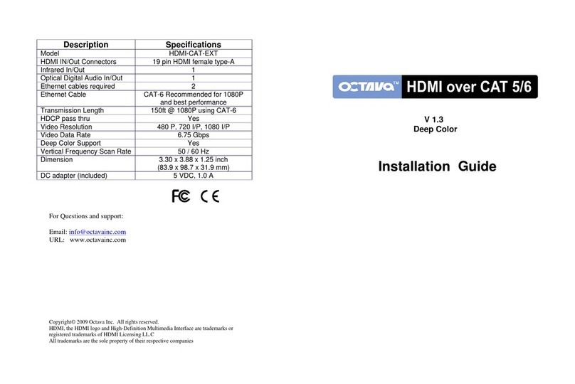
Octava HD70STP-EX User manual

1
HD70STP-EX
Installation Guide

2
Contents
Description...................................................................... 3
Features ......................................................................... 4
Application Diagram........................................................ 4
Front and Back Panel..................................................... 5
Installation....................................................................... 6
Ethernet cable installation recommendations ................. 7
IR Configuration.............................................................. 8
IR Emitter........................................................................ 9
LED Indicator.................................................................. 9
Serial Data(RS232)....................................................... 10
Mounting Tabs.............................................................. 11
Warranty....................................................................... 12
Disclaimers................................................................... 12
Specifications................................................................ 13

3
Description
The HD70STPEX HDMI extender simplifies HD video connectivity using 1
CAT6 cable. The HD70STP is a multi-format extender that extends 1080p,
4x2k ultra HD, 3D video and Advanced bitstream multichannel audio
formats 200ft on 1 single CAT 6 cable..
The HD70STPEX also extends IR, RS-232 controls and PoE power thus
simplifying installations while delivering high quality uncompressed 1080P
HD video and audio
Utilizes Power over Ethernet , PoE, to directly power the connected
HDSTP-70-RX receiver thus allowing clean and compact installations.
Bi-directional IR and RS-232 extension enable easy integration and
control of all connected devices via remote or 3rd part control systems.
Features
Extend HD video over 1 single CAT6 cable up to 200ft
Native uncompressed 1080P, and common 3D resolutions
supported
4K2k Ultra HD video resolution
Dolby Digital, DTS, Dolby Tru HD, DTS Master Audio pass thru.
Power over Ethernet, PoE, provides power to Zone Receiver
unit
Bi-Directional IR
Wideband IR 20-60 KHz circuitry for maximum IR remote
compatibility.
CEC passthru
RS-232 extension for controlling display device.

4
Application Diagram

5
Front and Back Panel
1
HDMI In
connect to video source
2
HDMI Out
connect to display
3
CAT6
Link TX unit with RX unit
4
IR RX
IR Receiver port
5
IR TX
IR Emitter port
6
Power In
Power Input. Powers transmitter
and Zone Receiver unit.
7
RS-232
Serial Port connection.
8
Power and Data LED
indicator
See page 9.
2.HDMI Out
1.HDMI In
3. CAT6
4. IR RX Port
7. RS-232 port
6. Power In
5. IR TX Port
HD70STP-TX
HD70STP-RX
8. LED indicator

6
Installation
HD70STP-TX(transmitter)
HD70STP-RX(receiver)
Installation Procedure
1
Connect “CAT6” of the Transmitter and Receiver
with CAT6 cable. (see page 7 for cable recommendations.)
2
Connect HD source to HDMI In of Transmitter unit
3
Connect Display to HDMI out of Receiver unit
4
IR connection(optional)-configure and connect as shown in
section: “ IR Configuration” (see page 8)
5
Serial connection(optional)-configure and connect as shown in
section: “Serial Data (RS-232)” (see page 10)
6
Connect power supply to the Transmitter
7
Verify that the PWR LED and Data LED Indicator are ON.
(see page 9)
8
Turn on Source and Display.

7
Ethernet cable recommendations
Using Shielded CAT6 (STP, 24AWG or better) or CAT7 cable will
ensure maximum signal integrity plus optimum rejection of external
interference.
Note 2- Unshielded CAT5e and CAT6 cables can be used with your
Octava system though they may result in limiting the maximum
attainable distance depending on quality of cable.
Cable Type
Note
1
CAT7 cable is recommended.
24AWG or better
Best
2
Shielded(STP) CAT6 cable is
recommended. 24 AWG or better
Recommended
3
UTP CAT5e/CAT 6 cable
Acceptable. Note 2
U Use EIA/TIA-568-B standard when terminating your LAN cables.
Ethernet cable installation recommendations:
Use your cable suppliers recommended RJ-45 connector/crimp tool
with your CAT5e, CAT6 or CAT7 cables and ensure you pay particular
attention to the quality of the termination on all cables.
DO / Recommend
Use shielded CAT6 or CAT7 with good RJ-45 terminators
Use a direct cable connection between the Transmitter and
R Receiver unit.
DO NOT
Do Not connect thru Ethernet switches or routers
For optimum signal integrity avoid passing your signals
though any form of Patch-panel, Wall-plate or punch-down
terminations.
Do Not connect cables thru extraneous RJ-45 couplers, wall
plates.
Do Not tightly coil /loop the Ethernet cables

8
IR Configuration
I.R. can be sent in 2 directions:
1) from Receiver to Transmitter or
2) from Transmitter to Receiver unit.
For proper operation, it is recommended that only Octava supplied
I.R. emitter and receiver cables be used.
Configuration 1: Sending IR from Receiver to Transmitter Unit
Connect IR Emitter to IR TX port
Connect IR Receiver to IR RX port
Configuration 2: Sending IR from Transmitter to Receiver Unit
Connect IR Receiver to IR RX port
Connect IR Emitter to IR TX port

9
IR Emitter
An IR Emitter cable has been included with your Octava Product.
The IR emitter cable enables you to control your source using I.R.
remote control.
1
Locate the IR receiver on
the video source. Note, you
may need to refer to your
source data sheet.
2
Remove the double sided
tape on the IR Emitter
3
Place the Emitter head over
the source IR receiver
LED Indicator
1
Normal operation:
Pwr LED =solid green,
Data LED =solid yellow
2
Lost Link:
Pwr LED =solid green,
Data LED =flashing yellow or off
3
No connection

10
Serial Data (RS-232)
Serial control data can be sent using the RS-232 ports from
Transmitter to Receiver unit for controlling the attached display.
A 3 pin Phoenix connector is provided to connect with a RS-232
serial cable. Prepare your serial cable according to diagram below
The following shows the cable configuration for sending serial
commands from the TX to the RX ( display side).
Sending Serial Commands from TX unit to RX Unit.
Serial Port cable
( TX side)
Controller
Side
Serial Port cable
( RX side)

11
Mounting Tabs
The HD70STP includes removable wall mounting tabs. The wall
mounting tabs can be removed if not needed
wall mounting tabs
installed
Wall mounting tabs
can be removed if
not needed.

12
Warranty
Octava warrants the equipment purchased to be free from defects in
material and workmanship under normal use and service for a period of 1
year. In the event applicable law imposes any implied warranties, the
implied warranty period is limited to 1 year from the date of receipt.
If Octava's equipment fails because of defects (1) year from the date of
receipt, Octava will at its option, A) repair or replace the equipment, or B)
request return of equipment for refund of the price paid for the product
provided that the equipment has not been subjected to mechanical,
electrical or other abuse or modifications.
Proof of sale required to claim warranty.
Disclaimers
IN NO EVENT SHALL OCTAVA'S OR ITS SUPPLIER’S LIABILITY FOR
ANY CLAIM WHATSOEVER EXCEED THE COST OF THE PRODUCTS
GIVING RISE TO THE CLAIM, WHETHER BASED IN CONTRACT,
WARRANTY, INDEMNITY OR TORT (INCLUDING, WITHOUT
LIMITATION, NEGLIGENCE AND STRICT LIABILITY) OR OTHERWISE.
IN NO EVENT SHALL OCTAVA INC. OR ITS SUPPLIERS BE LIABLE
FOR ANY SPECIAL, INCIDENTAL, CONSEQUENTIAL OR OTHER
INDIRECT DAMAGES (INCLUDING, WITHOUT LIMITATION, LOSS OF
REVENUES, PROFITS OR OPPORTUNITIES), HOWEVER CAUSED, ON
ANY THEORY OF LIABILITY, WHETHER OR NOT OCTAVA INC HAS
BEEN ADVISED OF THE POSSIBILITY OF SUCH DAMAGES.
WHILE EVERY PRECAUTION HAS BEEN TAKEN IN THE
PREPARATION OF THIS MANUAL, OCTAVA ASSUMES
NO RESPONSIBILITY FOR ERRORS OR OMISSIONS. IN NO
EVENT WILL OCTAVA ASSUME ANY LIABILITY FOR DAMAGES
RESULTING FROM THE USE OF THEINFORMATION CONTAINED HEREIN.
OCTAVA RESERVES THE RIGHTTO CHANGE THE SPECIFICATIONS,
FUNCTIONS OR CIRCUITRY OFTHE PRODUCT WITHOUT NOTICE.
For Questions and support:
Email: info@octavainc.com
URL: www.octavainc.com
Copyright© 2013 Octava Inc. All rights reserved.
HDMI, the HDMI logo and High-Definition Multimedia Interface are trademarks or
registered trademarks of HDMI Licensing LL.C
All trademarks are the sole property of their respective companies

13
Rev.D
Parameter
Specifications
Model
HD70STP-EX
HDMI In
1
HDMI Out
1
Link Distance CAT 6 Output
200ft @ 1080P
Video Resolution
1080P (60/50/24) , 720p(60/50), 1080i
(60/50), current 3D consumer formats
plus 4K.
Uncompressed high definition (HD)
video: 1080p@60Hz@36 bits
1080p@60Hz@48 bits, 3D, 4K x 2K up to
a distance of 40m/150ft
Audio
2ch PCM, multi-channel and Advanced
multi-channel bitstream digital audio
CAT6 IN/OUT
1
Power over Ethernet ( PoE)
Directly power the Zone receiver over
CAT 6 cables. No power supply required
near display side.
Infrared IR ( bi directional)
Bi -Directional IR. Send IR from display
side to source side OR vice versa.
Infrared Frequency
Wideband IR 20-60 KHz circuitry for
maximum IR remote compatibility using
Octava supplied IR cables.
Serial Port ( RS-232)
RS-232 extension for controlling display
device.
Ethernet Cable
Recommendation
CAT6 (Shielded, 24 AWG or better)
recommended for 1080P and best
performance
EIA/TIA-568-B termination (T568B) recommended.
Punch-down connection block/panel will degrade performance and
not recommended.
Use a single link of shielded CAT6a cable wherever possible.
Using a Keystone connector will reduce link distance
Dimension
Transmitter
4.53 x 3.58 x 1.26 in
(11.5 x 9.1 x 3.2 cm)
Receiver
4.53 x 3.19 x 1.14 in
(11.5 x 8.1 x 2.9cm)
DC adapter (included)
48VDC, 1 adapter included
Mounting Tabs
Included
Table of contents
Other Octava Extender manuals