OdorStop OS36PRO User manual

This System has an airow sensor
and must be installed in the HVAC
system in an area that has sufcient
airow to activate the sensor.
Please contact our customer care
department with any questions.
servic[email protected]om
1 (888) 956-7468
ATTENTION!

OdorStop, LLC
5139 Southwestern Blvd,
Hamburg, NY 14075 USA
Phone: 1 (888) 956-7468
Fax: 1 (716) 648-6406
www.OdorStop.com
Purchase Date: ____________________________________________
Serial Number: _____________________________________________
Purchased From: __________________________________________
© Copyright 2020. OdorStop, LLC
OS36PRO | OS72PRO | OS144PRO
UV Air Treatment System

READ INSTRUCTIONS COMPLETELY BEFORE INSTALLATION
Congratulations, you have purchased a state-of-the-art UV air treatment system. It is designed to oer
years of trouble-free service and sanitize the air to produce the cleanest, freshest air possible.
WARNINGS
UV LIGHTS CAN BE HARMFUL TO BARE SKIN AND EYES AND CAN CAUSE TEMPORARY OR
PERMANENT LOSS OF VISION.
• Never look at bulb(s) while illuminated.
• Disconnect power to Ultraviolet System before servicing any part of HVAC system.
• Do not mount device in location that allows ultraviolet light to be seen while in use.
• System has no serviceable parts and should never be opened.
• Power supply can cause electrical shock and death.
• Disconnect power supply before cleaning or replacing UV bulb(s).
• UV bulbs are made of glass and can cause personal injury.
• Wear protective gloves when handling bulb(s) and installing bulbs into system base.
• System should be turned o at least 15 minutes before removing UV bulb(s).
• Bulbs contain mercury and must be disposed of properly.
• Sweep up any broken glass and do not use a household vacuum.
• UV lights can cause degradation of some plastic and rubber materials. Plastic and rubber may be
covered with aluminum foil tape to protect them from the UV light.
• Take proper care when cutting holes or working with sheet metal as edges are sharp and can cause
severe injury and death. Wear protective gloves, eye, ear and face protection.
• To prevent water damage or electric shock, do not mount system under a humidier.
• Do not use UV system near water.
• System is designed for indoor installation on a closed duct system and should never be installed near a
return air opening.
• Be sure you are familiar with and able to safely use all tools required for installation.
1

INSTALLATION
How To Install Your OdorStop UV Air Treatment System
If your heating/cooling (HVAC) system is equipped with air
conditioning, it is recommended that the UV Air Treatment
System (unit) be mounted directly above the cooling coil. The
OS36/OS72 can prevent the growth of a high percentage
of micro-organisms such as mold, bacteria, and viruses on
surfaces such as cooling coils, drain pans, and duct work.
Selecting Mounting Location
1. If heating/cooling (HVAC) system is equipped with air
conditioning, it is recommended that the UV Air Treatment
System be mounted directly above the cooling coil (“A
Coil”).
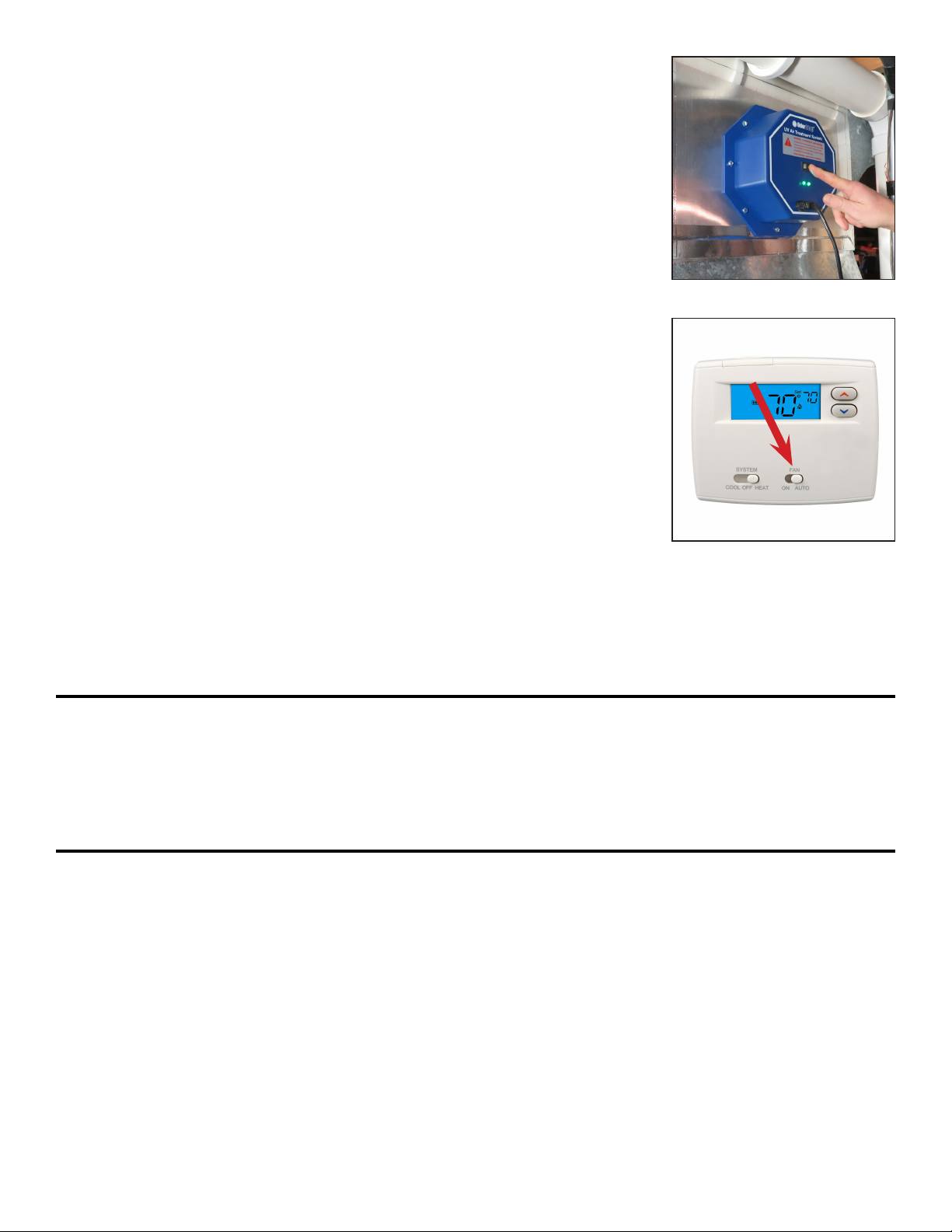
2. The unit can be mounted in any orientation, but should be
mounted in a way that the LED indicator light(s) can be seen.
3. Choose a location that will make changing/cleaning of the
UV bulb(s) easy.
4. Install unit on a at surface of the duct work ABOVE the air
conditioning cooling coil (“A Coil”) if your HVAC system has
air conditioning. If your HVAC system does not have air
conditioning, the unit should be installed on the supply air
duct if possible. The unit can be installed on a return air duct
if necessary.
CAUTION: DO NOT install the unit in the “A coil” or under
a humidier as damage may occur. If you are unsure if you
have chosen a correct mounting location, refer to your
HVAC system’s owners manual or call a qualied professional for assistance.
5. Select a mounting location that has a minimum depth of 17 inches if installing a system with 16” bulbs
and 13 inches for a system with 12” bulbs.
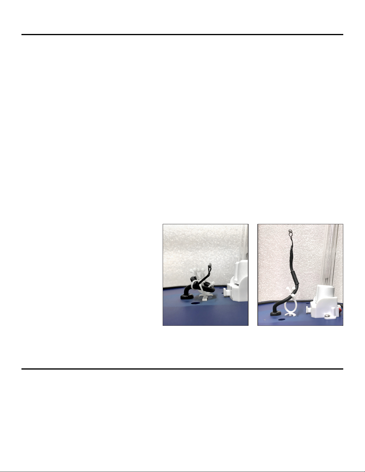
6. Be sure to locate the unit away from any plastic or rubber components that may be damaged by UV
light. If mounting options are limited, plastic and rubber may be covered with aluminum foil tape to
protect them from the UV light.
7. The unit has a 6 foot long power cord and must be installed within reach of a 120 Volt grounded power
outlet. Have a qualied professional install a properly grounded power outlet if there is not one within
range of the power cord.
Included:
• UV System
• 8 Sheet Metal Mounting Screws
• UV Bulb(s)-1 for OS36,
2 for OS72, 4 for OS144
• Spare Fuse
• Instruction Manual
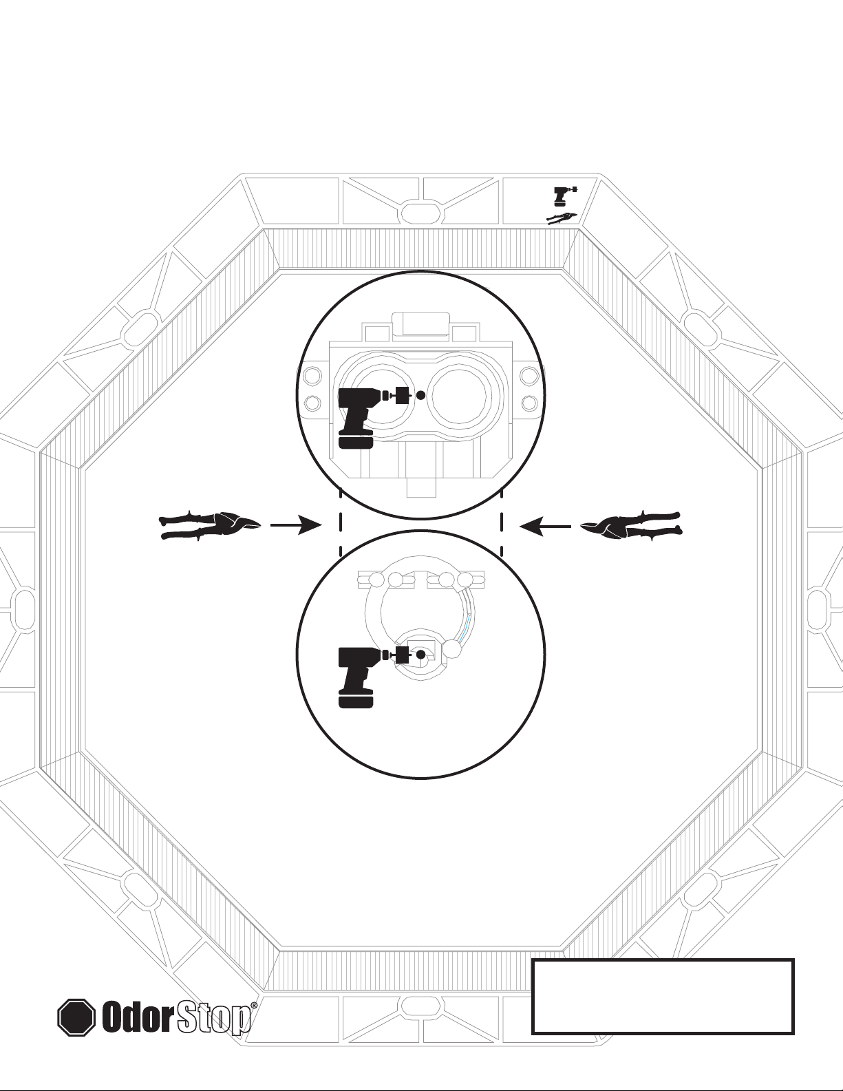
Tools Required For Installation:
• Drill
• 1/8” Drill Bit
• 1/4” Nut Driver
• Tin Snips
• 2 1/2” Metal Cutting Hole Saw
2

CAUTION: BE SURE TO WEAR APPROPRIATE PROTECTION (I.E. HAND, EAR, EYE, AND FACE
PROTECTION) AS CUTTING METAL IS LOUD AND PIECES MAY BE SHARP AND HOT
1. Turn the power to the HVAC system o before installing the system.
2. Select the correct template and tape it to the duct work in the intended
installation position.
3. For OS36 and OS72: Pre-drill two (2) 1/8” holes where indicated.
For OS144: Pre-drill four (4) 1/8” holes where indicated.
4. For OS36 and OS72: Drill two (2) - 2 1/2” holes where indicated.
For OS144: Drill four (4) - 2 1/2” holes where indicated. Remove any
burrs and be sure duct surface is at after cutting holes.
3

5. Take care to prevent the metal disc from falling into the HVAC system.
NOTE: If the disc falls into the HVAC system it will not negatively aect
its operation.
6. Use tin snips to cut out the metal ducting between the drilled holes
along dotted lines as shown in step 5.
7. Install bulb(s) by sliding them in from the inside until bulb snaps
into place. NOTE: If the bulb(s) are touched, use a cloth to wipe o
ngerprints.
8. Insert system into metal duct work.
4

5
9. Attach the system to duct work with the 8 sheet metal screws using a
¼” nut driver. Make sure to tighten screws evenly.
CAUTION: DO NOT OVERTIGHTEN SCREWS.
10. Plug the system into a grounded 120V power outlet.
Do not use an extension cord.
11. Turn the power to the HVAC system on.
12. Set the fan switch on the thermostat to the “ON” position.
NOTE: It is recommended that the system be run continuously for at
least 24 hours to “jump start” the sanitizing process. The UV System
will run as long as airow is detected. During this time, a unique odor
may be present as the UV System is killing mold, mildew, bacteria,
and viruses that are present.

13. Turn the system on (solid line on the switch pressed down) and verify
that the LED indicator light(s) are illuminated.
NOTE: The system will not turn on unless air is moving in the duct.
If green LED light(s) are not illuminated, see troubleshooting section.
UV air treatment system is now operational and does not need to be
powered o unless it needs to be serviced.
14. After 24 hours, set the fan switch on the thermostatm into “AUTO”
mode. The system is now operational and will only turn on when air
ow is detected.
NEVER LOOK DIRECTLY AT OR TOUCH A UV BULB WHILE ILLUMINATED.
Maintaining Your UV Air Treatment System
In order to keep your system operating at maximum eectiveness, it is recommended that you clean the
UV bulb(s) every 3 months and replace every year.
Bulb Cleaning and Replacement
1. Turn the power to HVAC system o, unplug UV system, and allow UV bulb(s) to cool for at least 15
minutes before attempting to remove UV system.
2. Remove 8 sheet metal screws and slide UV system out of duct work.
3a. To Clean: Hold the UV system securely and wipe the UV bulb(s) with a soft cloth dampened with glass
cleaner. If you touch the glass with your hand, be sure to wipe away any ngerprints or dirt with cloth.
Make sure bulb is clean and dry before installing system back into duct.
3b. To Replace: Visit www.OdorStop.com to purchase new UV bulbs if needed. Use of any bulb not
approved for system by OdorStop will void the warranty and could cause damage to system or
serious injury. Hold the UV system securely and push the bulb release button(s) to remove the UV
bulb(s). Install new bulb(s) in system by sliding the bulb(s) in from the inside until bulb snaps into
place. If you touch the glass with your hand, be sure to wipe away any ngerprints or dirt with a soft
damp cloth. Make sure bulb(s) is clean and dry before installing system back into duct.
6

7
Troubleshooting
The OdorStop UV Air Treatment System is equipped with LED indicator light(s) that verify that the system
is working properly. The OS36 has 1 LED, the OS72 has 2 LEDs, and the OS144 has 4 LEDs. The LED
light(s) will not shut o when the bulb needs replacement. They will only shut o if the bulb is faulty. The
OS72 and OS144 will operate with one properly functioning bulb.
LED lights indicate the following:
• LED light(s) is/are green - the system and bulbs(s) are functioning properly.
• One or more LED lights are blinking - Bulb(s) is/are faulty - replace the bulb(s). If LED does not turn on
solid green, system is faulty and should be replaced.
• One or more LED lights are not illuminated – possible problems:
• There is no power to the system – verify that system is plugged in and turned on.
• There is no air moving through the system – turn system on
• The bulb(s) is/are faulty - replace bulb(s).
• The fuse on the system is faulty - replace the fuse.
• Insucient airow to activate the airow sensor - The lead for the airow sensor must be extended
into ow of air as follows:
1) Turn the power to HVAC system o
and unplug UV system.
2) Remove the UV system.
3) Clip the “zip strip” and unwrap the
sensor lead from the stand o clips.
4) Extend the sensor lead away from
the UV bulb base.
5) Re-install the UV system and
follow instructions on page 5
of this manual.
SERVICE AND WARRANTY
OdorStop warrants to the original purchaser that this purier is free from any defect in materials and workmanship
for two (2) years from the date of purchase. OdorStop will replace or repair the system without charge to the
customer. This warranty does not include UV bulb(s). To obtain warranty service, please return the system in a
suitable package to: OdorStop Customer Service, 5139 Southwestern Blvd., Hamburg, NY 14075
Step 3 Step 4

CAUTION: BE SURE TO WEAR APPROPRIATE
PROTECTION (I.E. HAND, EAR, EYE, AND FACE
PROTECTION) AS CUTTING METAL IS LOUD
AND PIECES MAY BE SHARP AND HOT.
OdorStop UV Air
Treatment System
OS36PRO INSTALLATION TEMPLATE
STEP 1 - TAPE TEMPLATE TO DUCTWORK
STEP 2 - DRILL HOLES WITH 2 1/2” HOLE SAW
STEP 3 - SNIP METAL ALONG DASHED LINES
© Copyright 2019, OdorStop, LLC

CAUTION: BE SURE TO WEAR APPROPRIATE
PROTECTION (I.E. HAND, EAR, EYE, AND FACE
PROTECTION) AS CUTTING METAL IS LOUD
AND PIECES MAY BE SHARP AND HOT.
OdorStop UV Air
Treatment System
OS72PRO INSTALLATION TEMPLATE
STEP 1 - TAPE TEMPLATE TO DUCTWORK
STEP 2 - DRILL HOLES WITH 2 1/2” HOLE SAW
STEP 3 - SNIP METAL ALONG DASHED LINES
© Copyright 2019, OdorStop, LLC

CAUTION: BE SURE TO WEAR APPROPRIATE
PROTECTION (I.E. HAND, EAR, EYE, AND FACE
PROTECTION) AS CUTTING METAL IS LOUD
AND PIECES MAY BE SHARP AND HOT.
OdorStop UV Air
Treatment System
OS144PRO INSTALLATION TEMPLATE
STEP 1 - TAPE TEMPLATE TO DUCTWORK
STEP 2 - DRILL HOLES WITH 2 1/2” HOLE SAW
STEP 3 - SNIP METAL ALONG DASHED LINES
© Copyright 2019, OdorStop, LLC
This manual suits for next models
2
Table of contents
Other OdorStop Air Cleaner manuals
Popular Air Cleaner manuals by other brands

Pure n Natural Systems
Pure n Natural Systems LA-1000-FM Installation manual and user's guide

HoMedics
HoMedics AR-29A-GB instruction manual

GOLDENSEA UV
GOLDENSEA UV UVAIR300-F user manual

Westinghouse
Westinghouse Accu-Smart WAP811 owner's manual

Profroid
Profroid DUO operating instructions

ERRECOM
ERRECOM PureOzone Machine user manual

Flanders
Flanders Bolt Lock HEPA Filter Housing Surelock B Specification sheet

Milestone
Milestone HistosMATE Operator's manual

INNOLIVING
INNOLIVING INN-557 user manual

Daikin
Daikin STREAMER MCK55W Operation manual

Endress+Hauser
Endress+Hauser ISEmax 71072583 operating instructions

Sharp
Sharp KI-N50 Operation manual