odot ODOT-S1E1V2.0 User manual

http:// www.odotautomation.com 1/ 29 TEL: +86-0816-2538289
Protocol Converter
ODOT-S1E1V2.0
User Manual
V2.00
2020.03.16

http:// www.odotautomation.com 2/ 29 TEL: +86-0816-2538289
ODOT Series ODOT-S1E1V2.0
ODOT Automation System Co., Ltd.
2022-03
Copyright ©2012 ODOT Automation all rights reserved

http:// www.odotautomation.com 3/ 29 TEL: +86-0816-2538289
Version information
The following changes have been made to the document:
Date
version number
revise content
author
2020-07-20
V1.00
release version
CCL
2021-11-17
V1.01
firmware upgrading
CCL
2022-03-20
V2.00
hardware upgrading
CCL
Ownership rights information
Without the permission of the copyright owner,all or part of this document shall
not be republished as a paper or electronic document.
Disclaimer
This document is only intended to assist the reader in using the products, and the
company shall not be responsible for any loss or error caused by the use of the
information in this document. The product and text described in this document are
under constant development and refinement. ODOT Automation System Co., Ltd. has
the right to modify this document without notifying users.
Software download
Please log on the official website: www.odotautomation.com and click on the
corresponding product page to download.

http:// www.odotautomation.com 4/ 29 TEL: +86-0816-2538289
Catalogue
1. Product Overview ...................................................5
1.1 Product Functions ................................................5
1.2 Functional Characteristics..........................................5
1.3 Technical parameters..............................................6
2. Hardware description ................................................7
2.1 Product appearance ...............................................7
2.2 Indicator LED description..........................................8
2.3 Terminal definition ...............................................9
2.4 Reset switch ....................................................9
2.5 External terminal resistance .......................................11
2.6 Installation dimension............................................12
3. Typical application .................................................12
3.1 Transparent transmission with protocol data ..........................12
3.1.1 TCP_SERVER pattern ........................................13
3.1.2 TCP_CLIENT pattern ........................................15
3.1.3 UDP_CONNECT pattern: .....................................17
3.2 None protocol data transmission....................................20
3.2.1 TCP_SERVER pattern ........................................20
3.2.2 TCP_CLIENT pattern ........................................22
3.2.3 UDP_CONNECT pattern......................................23
4. Supplement .......................................................25
Brief introduction of serial port network topology .........................25
1. RS232 .......................................................25
2. RS422 .......................................................26
3. RS485 .......................................................28

http:// www.odotautomation.com 5/ 29 TEL: +86-0816-2538289
1. Product Overview
1.1 Product Functions
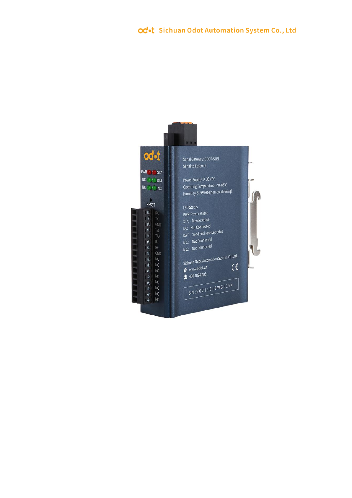
The protocol converter is a converter developed by Sichuan Odot Automation System
Co., LTD between RS232/485/422 and TCP/UDP. It can easily connect serial port
devices to Ethernet and realize network upgrade of serial port devices.
The protocol converter supports the function of "data transparent transmission",
which can be set as a client or a server. This function can easily realize the data
communication between PLC, server and other Ethernet devices and the underlying
serial port devices.
1.2 Functional Characteristics
◆ 9-36V wide voltage input, anti-reverse connection protection.DC-DC isolation
power supply, 3000V isolation voltage.
◆ 2KV network port isolation protection, 10M/100Mbps rate adaptive, automatic
MDI/MDIX reversal.
◆ Support TCP server pure transparent transmission, support 10 clients access.
◆ Support TCP client pure transparent transmission, support to connect 1 server.
◆ Support UDP pure transparent transmission.
◆ Support with and without protocol transparent transmission, protocol transparent
transmission supports MODBUS RTU/ASCII.
◆ Support for WEB browser configuration parameters.
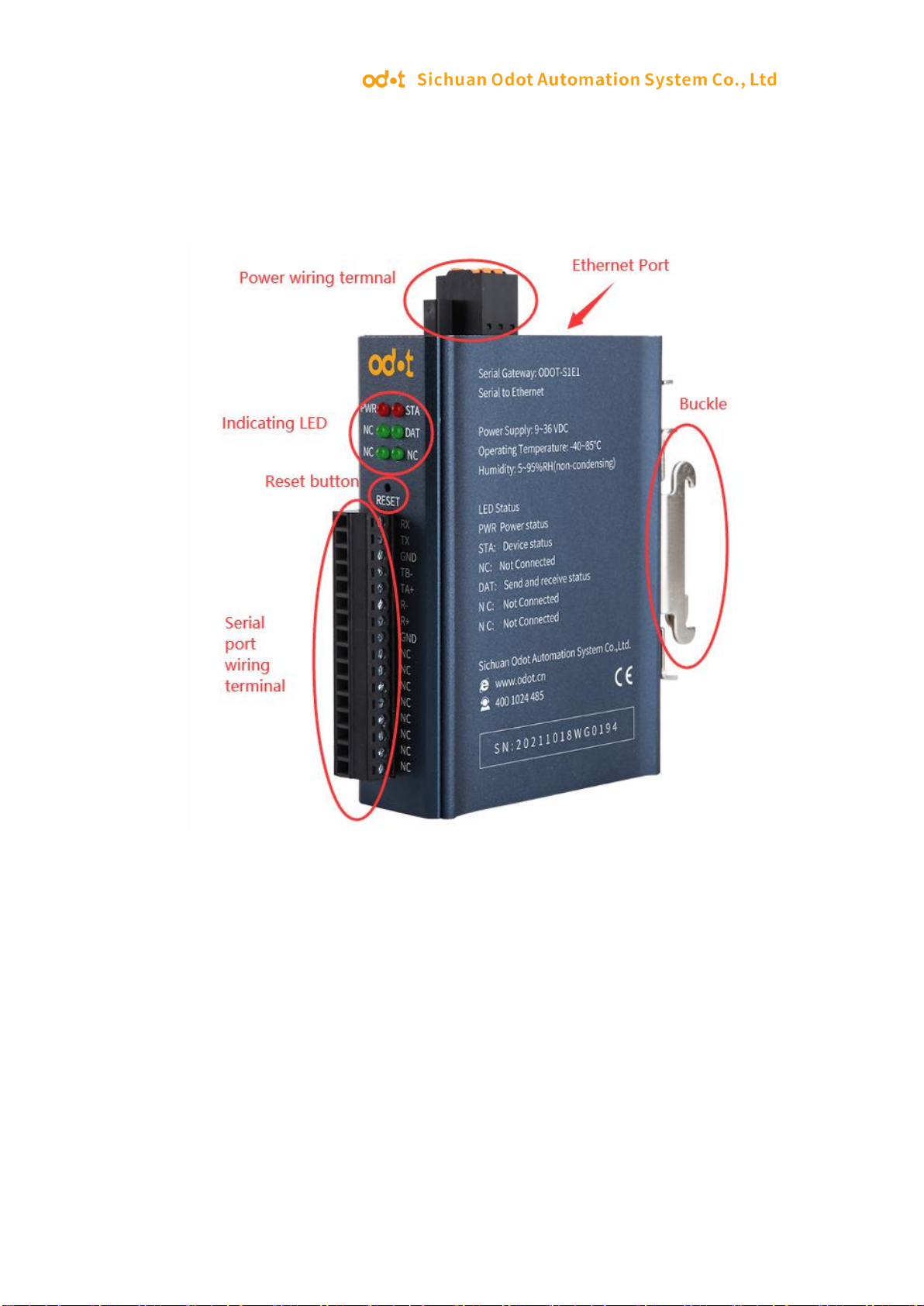
◆ It has three interfaces of RS485, RS422 and RS232.
◆ Serial port baud rate support 1200 ~ 115200bps
◆ Support DHCP, more convenient to use.
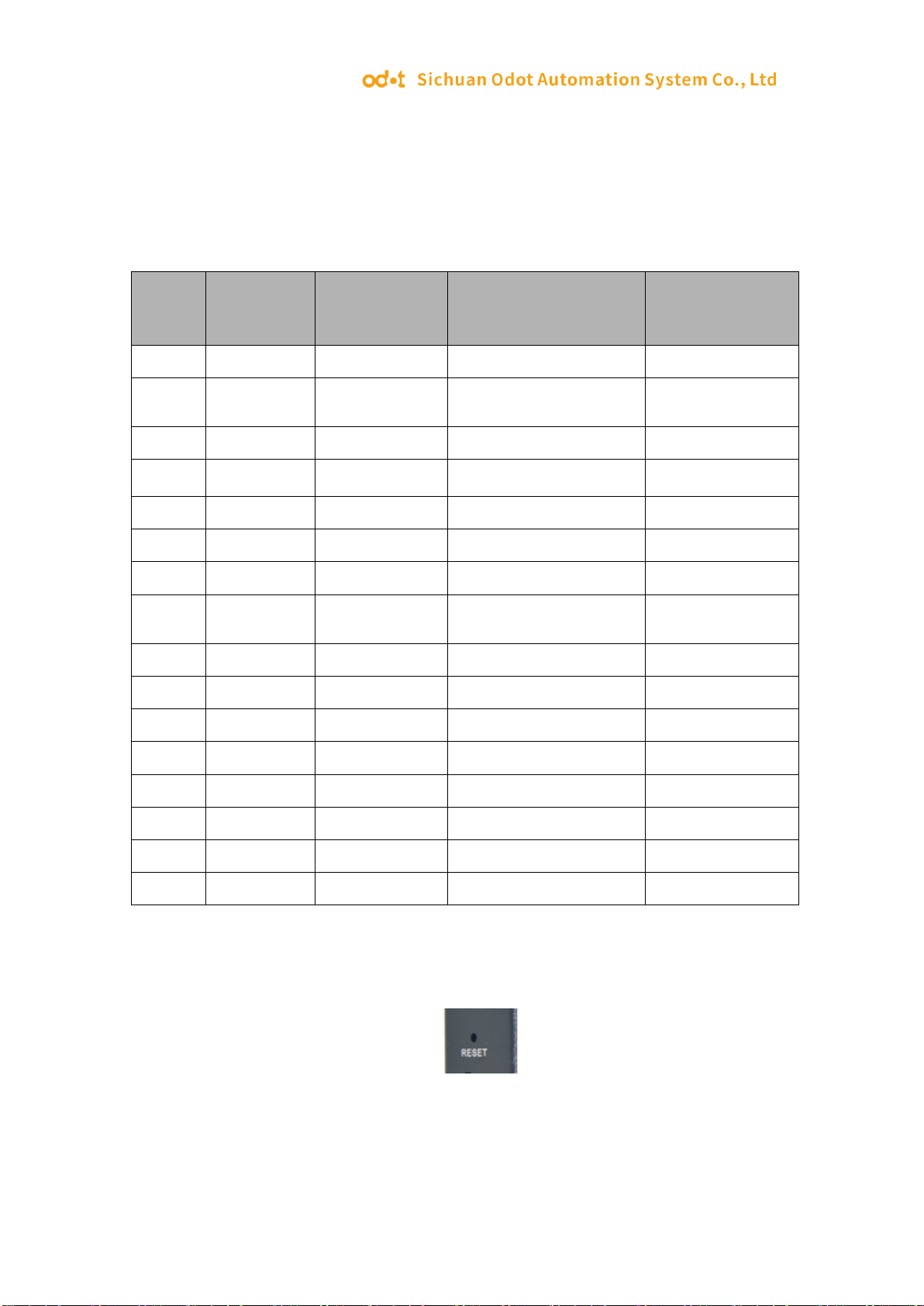
◆ Support one-key reset function to restore factory Settings.
◆ 35mm standard DIN-rail installation.
◆ EMC meets EN 55022:2010 & EN55024:2010 international standards.

http:// www.odotautomation.com 6/ 29 TEL: +86-0816-2538289
1.3 Technical parameters
The technical parameters of this product are shown in Table 3.1. Please use this
product within the parameters of this product to obtain better performance.
Table 3.1 Technical parameters
ODOT-S1E1
Environmental parameters
Working temperature
-20~70℃
Storage temperature
-55~125℃
Operating humidity
5%~95% (No condensation)
The power supply parameters
Number of power
ports
1
Input voltage
9-36V(DC)
Power consumption
700mW
Ethernet parameters
Working mode
TCP server,TCP client,UDP
Number of Ethernet
ports
1
Network protocol
TCP,UDP,HTTP
Number of TCP
connections
TCP server pure transparent transmission,supports 10 clients
accesses.
TCP client pure transparent transmission, support to connect
1 server.
Serial port parameters
Quantity of serial port
1
Serial communication
mode
RTU mode and ASCII mode are optional.
Serial terminal
resistance
120 Ω external resistance
Supported Baud rate
2400-115200bps
Supported validation
mode
None, odd check, even check
Number of slave
stations supported
31(RS485)

http:// www.odotautomation.com 7/ 29 TEL: +86-0816-2538289
2. Hardware description
2.1 Product appearance

http:// www.odotautomation.com 8/ 29 TEL: +86-0816-2538289
2.2 Indicator LED description
The converter has 5 LED status indicators, of which symbol definition and status
description are shown in "Table 2.1".
Table 2.1 Description of LED indicators
Symbol
Definition
State
Instruction
PWR
Power LED
ON
Power supply is connected
OFF
Power supply is not connected
STA
Converter status LED
Flash
The converter is running
properly
OFF
The converter is not running
properly
NC
Not used
OFF
Not used
DAT
Serial port transceiver
indicator
Flash
The serial port is sending and
receiving data
OFF
No data is being sent or
received through the serial port
NC
Not used
OFF
Not used
NC
Not used
OFF
Not used

http:// www.odotautomation.com 9/ 29 TEL: +86-0816-2538289
2.3 Terminal definition
The equipment connection adopts 10Pin 3.81mm distance unplugging terminal. The
RS485 interface terminal is defined as follows.
ODOT-S1E1 Terminal definition
2.4 Reset switch
The paper clip can be used to click the reset button, and all the indicators blink once
to indicate a successful reset. Gateway reset successfully, the technical parameters of
the gateway are as follows:
serial
numbe
r
Terminal
RS485
RS422
RS232
1
RX
RS232 receive
2
TX
RS232
transmission
3
SGND
RS232 grounding
4
TB-
RS485 B-
RS422 send negative
5
TA+
RS485 A+
RS422 send positive
6
R-
RS422 receive negative
7
R+
RS422 receive positive
8
SGND
RS485
grounding
RS422 grounding
9
NC
10
NC
11
NC
12
NC
13
NC
14
NC
15
NC
16
NC

http:// www.odotautomation.com 10 / 29 TEL: +86-0816-2538289
Device Info
Device name
S1E1
Firmware version
V1.452
Device ID
Network Configuration
Device IP
192.168.1.254
Device Port
502
Web access port
80
Operating mode
TCP server(default), TCP client, UDP
mode, UDP multicast
Subnet mask
255.255.255.0
Gateway
192.168.1.1
Destination IP/DNS
192.168.1.2
Destination port
1024
IP mode
Static (default), dynamic
Serial Port Configuration
Baud rate
1200-115200, default;115200
Data bit
5, 6, 7, 8; default: 8
Parity bit
None, odd check, even check;
default: None
Stop bit
1,2; default:1
Flow Control
None
Advance Level
None data restart
Disabled (default), Enabled
None data restart time
5-1270ms, default:300
Disconnection and
reconnection time
1-255 Second, default: 12
Multiple Host Settings
Conversion Protocol
Modbus TCP to RTU(default), None
Timeout time for
command response
32-8000ms, default:192
Multiple host setting
Enabled (default), Disabled
RS485 Idle time
interval
5-255ms,20
Change the web login password
New password
Retype new password

http:// www.odotautomation.com 11 / 29 TEL: +86-0816-2538289
2.5 External terminal resistance
According to the actual situation, a serial port side need external gateway 120 Ω
terminal resistance.RS485 bus in the case of no trunk to support a maximum of 32
nodes, node and node between the "Daisy chain" connection mode, in the
communication cable at both ends need to add terminal resistance, the resistance
value is required to be approximately equal to the transmission cable characteristic
impedance. In short distance transmission, no final resistance is required, that is, no
final resistance is generally required below 300 meters. The final resistance is
connected at the ends of the transmission cable.
Gateway in field application, if the RS485 bus distance, big field interference will
need to add 120 Ω on both ends of the RS485 bus terminal resistance, in order to
prevent the reflection of serial signal.
Note: 120 Ω resistance attached to the package, pay attention to check.

http:// www.odotautomation.com 12 / 29 TEL: +86-0816-2538289
2.6 Installation dimension
3. Typical application
S1E1 supports TCP server, TCP client, UDP pure transparent transmission mode. The
transparent transmission mode supports transparent transmission with and without
protocol. The S1E1 supports browser configuration and it directly forwarding data
without storing.
3.1 Transparent transmission with protocol data
Example: ODOT-S1E1 was used for testing. On-site RS485 device (MODBUS RTU
communication protocol is adopted for communication, serial port parameters:
ID=1,19200 BPS, N81). Modbus Slave test software was used to simulate the field
device.

http:// www.odotautomation.com 13 / 29 TEL: +86-0816-2538289
3.1.1 TCP_SERVER pattern
1.Open Google browser and enter 192.168.1.254 to login to the page configuration
interface:
Main nouns of configuration page Function description:
Baud rate:Serial port Baud rate, optional range 1200~115200bps, default 9600bps,
please set this parameter to be consistent with the device connected to the serial port.
Parity checking:No check, odd check, even check can be selected, default no check,
please set this parameter to the serial port.
Stop bits:1 t, 2 bit stop is optional, default is 1 bit stop. Set this parameter to match the
device to which the serial port is connected.
2. Network Settings: IP address 192.168.1.254, device port: 502, working mode: TCP
server.
Serial port Settings: Serial port parameters: 19200bps, N81. The Serial Port test tool
Serial Port Utility is used to simulate Serial Port devices.
Multi-master setting: Select Modbus TCP to RTU mode as the conversion protocol.
Click Submit when the Settings are completed.

http:// www.odotautomation.com 14 / 29 TEL: +86-0816-2538289
After the parameter settings are submitted, log in to the web page again to check
whether the Settings take effect.
Note: If the config page could not be logged in or the config page is displayed
abnormally, pls disable the wireless network card and log in again. If the login IP
address is forgotten, it could press the reset key to restore the factory Settings and log
in the converter through 192.168.1.254. And reconfigure the parameters before using.
4. After setting, open MODBUS POLL software to test whether the data is collected
normally.

http:// www.odotautomation.com 15 / 29 TEL: +86-0816-2538289
3.1.2 TCP_CLIENT pattern
1. Open Google browser, and enter 192.168.1.254 to log in to the webpage
configuration interface.
Network Setting: IP address 192.168.1.254, Device port: 502, Wok mode: TCP client,
set the Destination IP/DNS to the server IP address to be connected: 192.168.1.51 (IP
address of the local NIC), and remote port number: 6001.
Serial port device parameters: 19200bps, N81.The Serial Port test tool Serial Port
Utility is used to simulate Serial Port devices.
Multiple Host Config: Select Modbus TCP to RTU mode as the conversion protocol.
Click Submit when the Settings are completed.

http:// www.odotautomation.com 16 / 29 TEL: +86-0816-2538289
2. Open the TCP Debugging Assistant test tool, select TCP Server, set the remote host
IP address to 192.168.1.254, local port no: 6001, and click Start monitoring.

http:// www.odotautomation.com 17 / 29 TEL: +86-0816-2538289
Open Modbus Slave (simulate serial port device), click Connection or press the F3
shortcut key, set the correct serial port number and communication parameters in the
pop-up window, and click OK.
After the Settings, MODBUS master message is sent in the TCP debugging Assistant
sending window, and Automatic Sending is selected to collect MODBUS Slave data.
3.1.3 UDP_CONNECT pattern:
UDP is an unlinked protocol that does not establish a connection between the source

http:// www.odotautomation.com 18 / 29 TEL: +86-0816-2538289
and the terminal before transferring data. When it wants to transfer data, it simply
grabs the data from the application and throws it onto the network as quickly as
possible. At the sending end, the speed at which UDP delivers data is limited only by
the speed at which the application generates data, the capacity of the computer, and
the transmission bandwidth. At the receiving end, UDP puts each message segment
into a queue, and the application reads one message segment at a time from the queue.
1. Open Google browser, and enter 192.168.1.254 to log in to the webpage
configuration interface.
Network config: IP address 192.168.1.254, device port: 502, work mode: UDP, set the
destination IP/DNS to the server IP address to be connected: 192.168.1.51 (IP address
of the local NIC), and remote port number 6000. And it could use TCP debugging
assistant to simulate test for TCP side.
Serial port config: serial port parameters: 19200bps, N81.The Serial Port test tool
Serial Port Utility is used to simulate Serial Port devices.
Multiple Host Config: Select Modbus TCP to RTU mode as the conversion protocol.
Click Submit when the Settings are completed.

http:// www.odotautomation.com 19 / 29 TEL: +86-0816-2538289
TCP debugging assistant simulates UDP client, Modbus Slave simulates serial port
device, and it connects to S1E1 serial port through computer serial port USB to 485
converter.
Open TCP Debugging Assistant, select UDP, and set the remote host IP address:
192.168.1.254, remote port: 502, and local port: 6000. Click to enable UDP.
Open Modbus Slave (simulate serial port device), click Connection or press the F3
shortcut key, set the correct serial port number and communication parameters in the
pop-up window, and click OK.

http:// www.odotautomation.com 20 / 29 TEL: +86-0816-2538289
After the Settings, MODBUS master message is sent in the TCP debugging Assistant
sending window, and Automatic Sending is selected to collect MODBUS Slave data.
3.2 None protocol data transmission
3.2.1 TCP_SERVER pattern
1. Open Google browser, and enter 192.168.1.254 to log in to the webpage
configuration interface.
Network config: IP address 192.168.1.254, device port: 502, work mode: TCP server.
Table of contents
Other odot Media Converter manuals
Popular Media Converter manuals by other brands

Wieland
Wieland SENC Series installation instructions

SeaLevel
SeaLevel SeaPORT+2 user manual

Satcom Resources
Satcom Resources BC1X00 installation guide

Micronor
Micronor ESAV Series instruction manual

Extron electronics
Extron electronics Multi Video Processor MVP 104 Specifications

Keysight
Keysight E1418A Series Service guide