odot ODOT-S2E2 User manual

Protocol Converter
ODOT-S2E2
User Manual
V1.00
2020.07.21

ODOT Series ODOT-S2E2
ODOTAutomation System Co., Ltd.
2020-02
Copyright ©2019 ODOT Automation all rights reserved

Version information
The following changes have been made to the document:
Date
Version number
Revise content
Author
2014-09-15
V1.00
Release version
GJ
2014-12-05
V1.10
Release version
GJ
2015-04-10
V1.20
Release version
GJ
2016-07-14
V1.30
Release version
LJP
2017-06-06
V1.5.0
Release version
LJP
2018-06-01
V1.6.0
Hardware revision
CCL
2019-11-08
V1.7.0
WINCC application
IP address modification
CCL
2020-08-10
V1.8.0
Hardware revision
CCL
Ownership rights information
Without the permission of the copyright owner,all or part of this document shall not be
republished as a paper or electronic document.
Disclaimer
This document is only intended to assist the reader in using the products, and the
company shall not be responsible for any loss or error caused by the use of the information
in this document. The product and text described in this document are under constant
development and refinement. ODOTAutomation System Co., Ltd. has the right to modify
this document without notifying users.
Software download
Please log on the official website: www.odotautomation.com and click on the
corresponding product page to download.

Catalogue
1. Product Overview ................................5
1.1 Product Functions .....................................................5
1.2 Functional Characteristics...............................................5
1.3 Technical parameters...................................................6
2. Hardware description .....................................................7
2.1 Product appearance....................................................7
2.2 Indicator light description...............................................8
2.3 Terminal definition ....................................................8
2.4 Reset switch .........................................................9
2.5 External terminal resistance ............................................10
2.6 Installation dimension.................................................11
3. How to use the gateway ..................................................11
3.1 Introduction to how to use Gateway......................................11
3.1.1 Serial port working mode...........................................11
3.1.2 Gateway working mode............................................12
3.1.3 Gateway data storage area ..........................................12
3.1.4 System diagnosis area .............................................13
3.2 Default parameters ...................................................16
3.3 Gateway IP address modification ........................................17
3.4 Description of typical applications .......................................20
4. Supplement ............................................................55
Brief introduction of serial port network topology..............................55
1. RS232 ............................................................55
2. RS422 ............................................................56
3. RS485 ............................................58

1. Product Overview
1.1 Product Functions
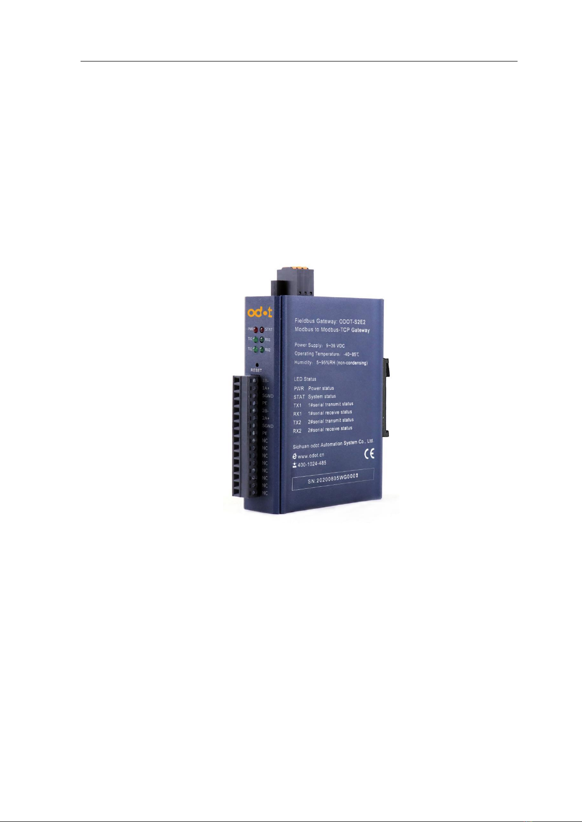
This product is a Modbus RTU/ASCII to Modbus TCP protocol converter developed
by Sichuan ODOT Automation System Co., Ltd based on market demand and years of
experience.
All slave devices that have RS485/RS422 interfaces and support Modbus RTU/ASCII
can connect to the Modbus TCP network through this gateway and communicate with TCP
clients. So as to realize the connection of low-speed serial devices to the high-speed
Ethernet to realize high-speed data transmission. The gateway has two different working
modes, "transparent" and "mapping", which can achieve maximum system compatibility.
1.2 Functional Characteristics
◆9-36V wide voltage input, anti-reverse connection protection. DC-DC isolated
power supply, 3000V isolation voltage.
◆2KV network port isolation protection, 10M/100Mbps rate adaptive, automatic
MDI/MDIX flip.
◆Small size, only 30mm thickness, saving installation space.
◆Support address mapping mode to realize fast response to TCP client request.
◆Support up to 5 TCP client access.
◆The mapping mode supports function codes:
0x01,0x02,0x03,0x04,0x05,0x06,0x0F,0x10.
◆The transparent transmission mode supports all public function codes and custom
function codes.
◆6KB large data buffer area, larger data transfer volume.
◆RS485 dual serial port refreshes in real time, with short scanning period and strong
load capacity.
◆The master and slave modes of RTU and ASCII are optional, which is highly
adaptable.
◆The watchdog can be enabled and the watchdog time can be set.

◆Support IAP download, it supports for updating the firmware program in the product
through the network port.
◆RS485 with surge protection, built-in bias circuit, strong stability. An external
terminal resistor is required.
◆The data packet sending interval can be adjusted freely, making it more flexible to
use.
◆The device comes with a powerful diagnostic function to monitor the
communication status in real time.
◆Support one-key reset function to restore factory settings.
◆35mm standard rail installation.
◆EMC complies with EN 55022:2010 & EN55024:2010 international standards.
1.3 Technical parameters
The technical parameters of this product are shown in Table 3.1. Please use this
product within the parameters of this product to obtain better performance.
Table 3.1 Technical parameters
ODOT-S1E1
ODOT-S2E1
Environmental parameters
Working temperature
-40~85℃
Storage temperature
-55~125℃
Operating humidity
5%~95% (No condensation)
The power supply parameters
Number of power
ports
1 road
Input voltage
9-36V(DC)
3KV isolation voltage
Power consumption
Max.100mA@24V
Ethernet parameters
Working mode
Transparent transmission mode, address mapping mode
optional, Modbus TCP protocol
Number of Ethernet
ports
2 RJ45, 2KV surge protection, 10M, 100M adaptive rate 1
Network protocol
ETHERNET、ARP、IP、TCP、ICMP
Number of TCP
connections
Max 5
Serial port parameters
Quantity of serial port
Dual RS485

Serial communication
mode
RTU mode and ASCII mode are optional.
Serial terminal
resistance
120 Ω external resistance
Supported Baud rate
1200~115200 bps
Supported validation
mode
No check, odd check, even check
Number of slave
stations supported
Maximum 62 (without repeater)
Mapping mode
protocol function
code
0x01、0x02、0x03、0x04、0x05、0x06、0x0F、0x10
Modbus data storage
area
0xxxx area (coil): 8192 Bit
1xxxx area (discrete input): 8192 Bit
3xxxx area (input register): 2048 Word
4xxxx area (holding register): 2048 Word
3xxxx area (system diagnosis area): 263 Word
2. Hardware description
2.1 Product appearance

2.2 Indicator light description
The equipment has five LED status indicator lights, whose symbol definition and status
description are shown in "Table 2.1".
Table 2.1 Description of indicator light
Caution:*——During normal communication, the status of the ODOT-S2E2 gateway
indicator
2.3 Terminal definition
The equipment connection adopts 3 Pin and 16Pin 3.81mm distance unplugging
terminal. The RS485 interface terminal is defined as follows.
RS485 terminal definition
Symbol
Definition
State
Instruction
PWR
Power Light on/off
ON
Power on
OFF
Power off
ETH
Gateway status indication
ON
TCP gateway communication
error
OFF
TCP gateway communication
normal
TX1
Serial port no.1 send
indicator light
ON
Serial port no.1 data is being
sent.
OFF
Serial port no.1 sends no data.
RX1
Serial port no.1 receiving
indicator light
ON
Serial port no.1 data is being
received.
OFF
Serial port no.1 receives no
data.
TX2
Serial port no.2 sending
indicator light
ON
Serial port no.2 has data being
sent.
OFF
Serial port no.2 no data sent.
RX2
Serial port no.2 receiving
indicator light
ON
Serial port no.2 has data being
received.
OFF
Serial port no.2 receives no
data.
serial
Terminal
Definition

Power terminal definition
2.4 Reset switch
The paper clip can be used to click the reset button, and all the indicators blink once to
indicate a successful reset. Gateway reset successfully, the technical parameters of the
gateway are as follows:
numbe
r
1
1B-
Serial port no.1 RS485-
2
1A+
Serial port no.1 RS485+
3
SGND
Signal ground
4
PE
Shield Earthing
5
2B-
Serial port no.2 RS485-
6
2A+
Serial port no.2 RS485+
7
SGND
Signal ground
8
PE
Shield Earthing
9-16
NC
serial
numbe
r
Terminal
Definition
1
PE
Shield Earthing
2
V-
24Vdc-
3
V+
24Vdc+

2.5 External terminal resistance
According to the site situation, the serial port side of gateway needs external 120 Ω
terminal resistance. The RS485 bus supports a maximum of 32 nodes without relay,
A "daisy chain" connection is used between nodes, and terminal resistors are required at
both ends of the communication cable, and their resistance is required to be approximately
equal to the characteristic impedance of the transmission cable. In short-distance
transmission, no terminating resistor is required, that is, no terminating resistor is generally
required below 300 meters.
The terminating resistor is connected to the two ends of the transmission cable. When
Parameter Name
Defaults
Ethernet
side
Protocol converter IP
192.168.1.254
Subnet mask
255.255.255.0
LAN gateway IP
192.168.1.1
Modbus TCP data port
502
Configure the por
1024
Modbus-TCP watchdog time
30S
The enabling of Modbus-TCP
watch dog
enable
Gateway work mode
Transmission Mode
Gateway station Number
247
Serial
side
Serial port mode
Master station mode
Protocol type of Modbus
Modbus RTU
Serial port baud rate
9600bps
Check digit
No check
Data bits
8bit
Stop bit
1bit
Receive character interval
3.5t
Message sent
0
Timeout processing
Data retention
Slave response timeout
500ms

the gateway is used in the field, if the field RS485 bus is far away and the field interference
is large, it is necessary to add 120Ω terminal resistance at both ends of the RS485 bus to
prevent the reflection of the serial signal.
Note: 120 Ω resistance attached to the package, please check it.
2.6 Installation dimension
3. How to use the gateway
3.1 Introduction to how to use Gateway
3.1.1 Serial port working mode
There are two types of working modes: Master mode and slave mode.
When the serial port works in the master station mode, the serial port can connect up

to 31 Modbus RTU/ASCII slave devices without relay; this mode is mainly used for the
communication between the Modbus TCP master station and the Modbus RTU/ASCII slave
station.
When the serial port works in slave mode, the serial port can be connected to a Modbus
RTU/ASCII master device; this mode can be used for the following applications:
(1) Realize data communication between Modbus TCP client and Modbus RTU/ASCII
master station;
(2) Realize data communication between Modbus RTU/ASCII master stations;
(3) Realize Modbus TCP client and a Modbus RTU/ASCII master to communicate
with a Modbus RTU/ASCII slave at the same time.
3.1.2 Gateway working mode
The gateway has two working modes, "transparent" and "mapping", and it is in
"transparent" mode under factory settings. There is no data buffer in the "transparent
transmission" mode, and there is no need to edit the slave address mapping table. After
receiving the command from the Modbus TCP client, the gateway directly sends the
command to the Modbus RTU/ASCII slave device and waits for the slave device to respond
After the slave device responds, it directly returns the data to the TCP client. The "mapping"
mode adopts the data buffer mode, and the slave station address mapping table needs to be
edited. After the gateway is powered on, the slave stations are polled and the data is stored
in the data buffer area. After the gateway receives the command from the Modbus TCP
client, it reads the data from the data buffer area and returns the data to the TCP client. This
method can greatly reduce the waiting time when the client accesses the slave station and
increase the refresh rate.
3.1.3 Gateway data storage area
The data storage is divided into five parts, the first part is the "coil" (DO) storage area
with a total of 8192 points. The second part is the "discrete input" (DI) storage area with
8192 points in total. The third part is the "input register" (AI) storage area, with a total of
2048 words. The fourth part is the "holding register" (AO) storage area with a total of 2048
words, and the fifth part is the "system diagnosis" storage area, which stores the working
status of the slave device, with a total of 263 words. Visit the "system diagnostic area" to
obtain slave station information, which can be used to set slave station disconnection alarms

and other functions. The data storage area allocation and address coding range are shown in
"Table 3.1".
Table 3.1 Data storage area address table
3.1.4 System diagnosis area
The system diagnosis is divided into two parts. The first part: Address 0x2000-0x200F
has 16 words i.e. 256 bits, which is the "slave station error indication area". The bits
numbered 1-247 correspond to the slave stations with address 1-247. , The bits numbered
248-256 are reserved. When an error occurs in the slave communication, the bit
corresponding to the slave address is set to 1. The corresponding error indication bit will be
automatically cleared after the slave station returns to normal. The data encoding format is
shown in "Table 3.2".
Table 3.2 Coding format of slave error indication area
No.
Storage
category
Description
Storage capacity
Address range
1
Zone 0
coil
8192 Bit
0x0000~0x1FFF
2
Zone 1
Discrete input
8192 Bit
0x0000~0x1FFF
3
Zone 3
Input register
2048 Word
0x0000~0x07FF
4
Zone 4
Holding register
2048 Word
0x0000~0x07FF
5
Zone 3
System diagnosis
263 Word
0x2000~0x2106
Address
0x2000
BIT
Bit15
Bit14
Bit13
Bit12
Bit11
Bit10
Bit9
Bit8
Bit
number
16
15
14
13
12
11
10
9
BIT
Bit7
Bit6
Bit5
Bit4
Bit3
Bit2
Bit1
Bit0
Bit
number
8
7
6
5
4
3
2
1
Address
0x2001
BIT
Bit15
Bit14
Bit13
Bit12
Bit11
Bit10
Bit9
Bit8
Bit
number
32
31
30
29
28
27
26
25
BIT
Bit7
Bit6
Bit5
Bit4
Bit3
Bit2
Bit1
Bit0
Bit
number
24
23
22
21
20
19
18
17

The second part: The address 0x2010-0x2106 has a total of 247 words, which is the "slave
station status indication" area. Reading this area can get the current working status of the
slave station. The data encoding format is shown in "Table 3.3".
Table 3.3 Coding format of slave status indication area
Each Word is divided into high and low bytes. Byte1 is the high byte, indicating the
function code currently executed and mapped to the slave. Byte0 is the low byte, indicating
the error code of the current slave communication. The specific meaning of the slave error
codes is shown in "Table 3.4".
.
.
.
Address
0x200F
BIT
Bit15
Bit14
Bit13
Bit12
Bit11
Bit10
Bit9
Bit8
Bit
number
x
x
x
x
x
x
x
x
BIT
Bit7
Bit6
Bit5
Bit4
Bit3
Bit2
Bit1
Bit0
Bit
number
x
247
246
245
244
243
242
241
Address
0x2010
Slave
station 1
Byte1
Byte0
Function code
Error code
Address
0x2011
Slave
station 2
Byte1
Byte0
Function code
Error code
.
.
.
Address
0x2106
Slave
station
247
Byte1
Byte0
Function code
Error code

Table 3.4 Description of Slave Error Code
Error
code
Fault description
Troubleshooting method
0x00
works normally
None
0x01
Illegal function
code
The device does not support the current function
code, please refer to the slave station manual to select
the corresponding function code module
0x02
Illegal data address
The device data exceeds its address range, refer to
the slave station manual to modify the data start
address or data length
0x03
Illegal data value
Data length error, the data length exceeds the
maximum allowable value of 125 (Word) or 2000
(Bit), modify the length
0x04
Data processing
error
Check whether the data value range meets the
requirements of the slave
0x05
The length of the
application layer
does not match
Increase the receiving character interval and check
the communication parameter settings
0x06
Protocol ID error
Check the sender message
0x07
Cache address error
Device internal error
0x08
Bit offset error
Device internal error
0x09
Slave station ID
number does not
match
Increase the timeout time, check the hardware
connection status, and check the communication
parameter settings
0x0A
CRC error
CRC error, check the communication line
0x0B
LRC error
LRC error, check the communication line
0x0C
Response function
code does not match
Check hardware connection status
0x0D
Response address
does not match
Check hardware connection status
0x0E
Response data length
does not match
Check hardware connection status
0x0F
Communication
timeout
Increase the timeout time, check the hardware
connection status, and check the communication
parameter settings
0x10
ASCII mode start
character error
„:‟ colon start character error
0x11
ASCII mode
terminator error
CR/LF carriage return and line feed terminator error

3.2 Default parameters
The default factory configuration of the gateway is as follows:
Table 3.5 Factory default configuration of gateway
Note: The gateway factory-set work under transparent transmission mode can be used
without configuration. At this time, all request data of the TCP client is sent to the serial port
0x12
Non-character data
in ASCII mode
The data contains non-hexadecimal ASCII codes
0x13
The number of
characters in ASCII
mode is wrong
The response length of the slave is wrong
Parameter name
Default value
Ethernet
side
Ethernet side protocol converter IP
192.168.1.254
Subnet mask
255.255.255.0
LAN gateway IP
192.168.1.1
Modbus TCP data port
502
Configure port
1024
Modbus-TCP watchdog time
30S
Whether Modbus-TCP watchdog is
enabled
Enable
Gateway working mode
Transparent transmission mode
Gateway station number
247
Serial
side
Serial working mode
Master mode
Modbus protocol type
Modbus RTU
Serial port baud rate
9600bps
Check digit
No check
Data bits
8 bits
Stop bit
1 bit
Receiving character interval
3.5t
Message sent Ange
0
Timeout processing method
Data retention
Slave response timeout time
500ms

1. If you want to configure the parameters of the gateway, please use the software "ODOT
MGCC Config" for configuration. The software installation package is in the CD-ROM, or
you can call the Sichuan Odot Automation System Co., Ltd. hotline: +86-816-2538289.
3.3 Gateway IPaddress modification
First, supply 24VDC to the gateway, connect the network cable to the gateway and the
computer, change the computer's local network card IP address to the 192.168.1.* network
segment, then open the configuration software MGCC Config, click upload gateway
configuration, and ensure normal communication with the gateway (can normally upload
and download the gateway configuration).

Modify the gateway IP address of the configuration software interface to:
192.168.10.12 (cross-network segment), and change the LAN gateway IP to: 192.168.10.1.
After the modification is completed, click to download the gateway configuration directly,
and a warning box will pop up to confirm whether to modify the IP address. Click OK, you
can see the download is successful in the lower right corner.

After the IP address is successfully modified, you need to change the computer's IP
address to: 192.168.10.* network segment.
Click Upload Gateway Configuration on the configuration software MGCC Config
interface.After the upload is successful, you can see the upload success in the lower right
corner.

3.4 Description of typical applications
3.4.1 Communicate between Modbus TCP client and Modbus
RTU/ASCII slave station
3.4.1.1 Application topology
Table of contents
Other odot Media Converter manuals