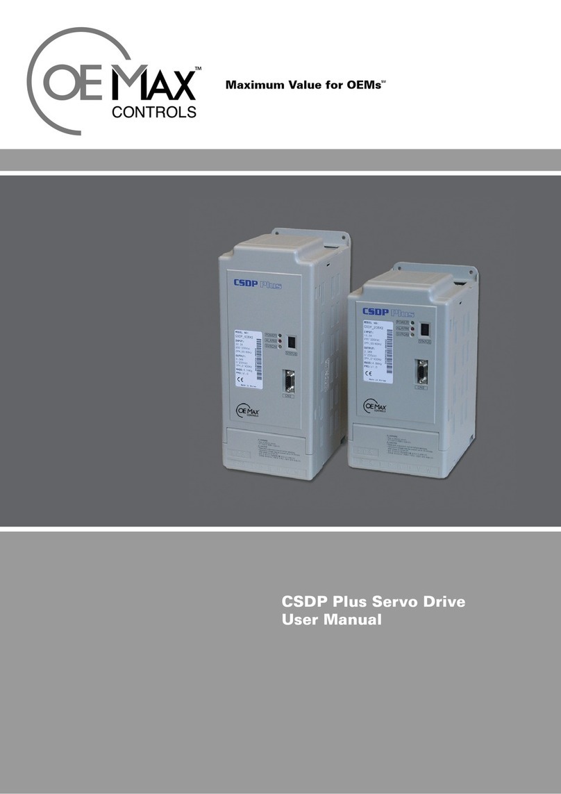
OE Max Controls CSDJ Plus User manual


English
Contents
Before Use .........................................................................5
Safety Instructions................................................................................................5
Operation..........................................................................................................6
Storage.............................................................................................................6
Carrying............................................................................................................6
Installation and Wiring....................................................................................7
Maintenance & Checkup.................................................................................7
Checkpoints on Product Delivery........................................................................8
Servo Drive.......................................................................................................8
Servo Motor.....................................................................................................9
Installation and Test Run .................................................11
Installation and Wiring.......................................................................................11
Installation......................................................................................................11
Wiring.............................................................................................................13
Cautions for Wiring...................................................................................... 14
Test Run...............................................................................................................15
Power Input and Motor Configuration.........................................................15
Gain Tuning....................................................................................................17
Operator Test Run .........................................................................................19
Troubleshooting ............................................................................................20

4
Important User Information
Solid state equipment has operational characteristics differing from those
of electromechanical equipment. Because of this difference, and also
because of the wide variety of uses for solid state equipment, all persons
responsible for applying this equipment must satisfy themselves that each
intended application of this equipment is acceptable.
In no event will OE Max Controls be responsible or liable for indirect or
consequential damages resulting from the use or application of this
equipment.
The examples and diagrams in this manual are included solely for
illustrative purposes. Because of the many variables and requirements
associated with any particular installation, OE Max Controls cannot
assume responsibility or liability for actual use based on the examples and
diagrams.
No patent liability is assumed by OE Max Controls with respect to use of
information, circuits, equipment, or software described in this manual.
Reproduction of the contents of this manual, in whole or in part, without
written permission of OE Max Controls is prohibited.
Throughout this manual we use notes to make you aware of safety
considerations.
Identifies information about practices or circumstances
which may lead to serious personal injury or death,
property damage, or economic loss.
Identifies information that is critical for successful
application and understanding of the product.
Identifies information about practices or circumstances
that can lead to minor personal injury, property damage,
economic loss, or product malfunction. However,
depending on situation, failure to follow the directions
accompanying this symbol may also lead to serious
consequences.
IMPORTANT
ATTENTION
WARNING
ATTENT IO N
IMPORTANT

5
1
Before Use
Safety Instructions
Please read the instructions and the User Manual thoroughly. It is
important that you become familiar with the operational issues prior
to installing and operating the machinery, to ensure optimal
error-free operation and maximize safety.
Before you start
•This manual is a summary of the required procedures that all
users must know for the proper handling, installation, and
execution of product test runs. It may not provide sufficient
information in all cases. Please refer to the User’s Manual for more
details.
•Product guarantees are not applicable in cases where modification
of the device by the user has been made in ways other than those
stated in this manual.
•In no case will OE Max Controls be responsible or liable for any
personal injury or property damage that is the result of improper
modification of the product.

6
Operation
•Never touch the inside of the servo drive with your
hand.
•Make sure your servo drive and motor are grounded.
•Handle the drive only when the power is off and the
product is completely free of potential discharge.
(The lamplight will appear completely turned off.)
•Avoid excessive stress on the motor’s power supply
and encoder cables.
•Never touch the revolving motor component during
operation.
•Avoid operation in environments that are subject to
conditions of humidity, corrosion, and flammability.
•Operate without load during test runs.
•The cooling panel of the drive is extremely hot while
in operation. Special caution is required at these
times.
Storage
•Avoid rain and humidity, and corrosive gases and
liquids.
•Avoid direct sunlight and high temperatures and
avoid humidity levels that are outside the optimal
operational ranges.
•Avoid overload of products in storage.
Carrying
Don’t move or carry the device by its cable or motor
shaft.
ATTENT IO N
WARNING
ATTENT IO N
ATTENT IO N

7
Installation and Wiring
•To prevent system damage caused by overheating,
the cooling system specifications must be included in
the design with consideration to ambient
temperature.
•The cooling panel of the servo drive is extremely hot
during operation. Avoid the placement of wiring
cables in close proximity to the panel.
•To prevent the negative impacts of noise and heat,
allow the separation of at least 10mm of space
between the drives if you are installing multiple
drives.
•While wiring, we recommend highly that you make
allowance for the negative potential impact of noise.
Maintenance & Checkup
•Do not disassemble the device. The product warranty
is not applicable in cases of modification to the
product by the user in ways that are not
recommended by the stated procedures in this
manual. OE Max Controls is not responsible for
personal injury or property damage that is the result
of unsanctioned modifications to the product
•Regular maintenance is critical for components with
limited service lives, and may require periodic
replacement due to normal mechanical friction and
degradation.
•In case you cannot perform periodic troubleshooting,
contact our Technical Support Team or Customer
Service Center.
ATTENTION
ATTENTION
ATTENTION

8
Checkpoints on Product Delivery
Please check the following on product delivery:
•Please check to see if the delivered product is identical with what
you ordered by referring to the legend.
•Check the screw contacts, lead shorts, insulators, and any other
signs of possible or apparent damage.
•For motors without brakes, turn the shafts with your hands and
verify that it revolves smoothly.
Servo Drive
Refer to the following legend, and verify that the model name written
on the nameplate on the side of the device is identical to that on your
order.
Symbol Rated
Output
01 100[KW]
02 200[KW]
04 400[KW]
06 600[KW]
10 1[KW]
C
Symbol Input Voltage
B AC220[V]
S D J 0 1 B X 2 O M

9
Servo Motor
Refer to the following legend, and verify that the model name that is
written on the nameplate on the servo motor device is identical to
that on your order.
Motor Model Rated Output Input Voltage
CSMT
A3 30W B AC220V
A5 50W
01 100W
02 200W
04 400W
06 600W
08 800W
10 1KW
CSMR
01 100W
02 200W
04 400W
The nameplate is attached on the motor. Check the model name on it.
Motor Model
C S M T 0 1 B B 1 A N T O M
Motor Specification Symbol
3
Rated Output
Input Voltage
Encorder Type
Design No.
Motor Shaft Key
Option
Manufacturer
Motor Shaft Type

10
Encoder Type
CSMT, CSMR Motor
B 2048P/R 9 Wire Incremental Type
Motor Shaft Key Option Motor Shaft Type
A Key N No Option 1 Round
(Coupling Contact)
B No Key B Brake 3 Key Contact

11
2
Installation and Test Run
Installation and Wiring
Installation
Servo Drive
Front View Natural Convection
The Servo drive is designed to be mounted from the bottom. The following mounting direction is optimized to promote
the air cooling effects of natural convection. Make sure to mount the Servo Drive in this position to maximize the drive’s
integrity and operational life.
When installing multiple Servo drives, follow these guidelines:
Install the cooling fans to prevent the drives from overheating. The drives performance will become severely
compromised if they frequently operate in conditions that are outside the acceptable temperature range.
Over 50[mm]
Cooling Fan Cooling Fan
Over 50[mm]
Over 30[mm]
Outside Wall
Outside Wall
Over 10[mm]

12
Servo Motor
•Avoid excessive pressure to the motor shaft when it
has an attached load on the shaft. The encoder can
easily be damaged.
•Position the load shaft to align it with the motor shaft.
•Make sure the vertical and horizontal loads on the
motor shaft do not exceed the acceptable load range.
Refer to the User’s Manual for information on the
loads that the motor shaft can safely withstand.
•Avoid excessive stress on the motor power supply
and the encoder cables.
Installation Environment
Item Environment
Storage
Temperature -20 ~80[°C]
Operating
Temperature 0 ~55[° C]
Operating
Humidity Motor: 20 ~ 80[%] (non-condensing)
Servo Drive: below 90[%] (non-condensing)
Vibration 0.5[g] (4.9[m/s2])
Ambient
Please work to keep the temperature within the
acceptable operating temperature range. If you
experience chronically excessively high ambient
temperatures, please install additional coolers.
Recommended: For greater reliability and longer life,
operate the device at temperatures between 0 and
45[° C].
Your indoor operational environment must have
adequate ventilation, visibility, and easy access to
perform routine maintenance. Avoid the presence of
volatile gases.
ATTENTION

13
Wiring
•Only use power cables with capacities of over 600W.
•Maintain the operating temperature between 40° C
and 60° C. Use a heatproof cable for operation outside
of this temperature range.
•I/O wiring is not required for a test run(jog run). Refer
to the User’s Manual for information on I/O wiring for
best practices system construction.
•The diagram above is recommended for complete
systems only. The power breaker is sufficient, and is
the only requirement for a test run.
Use a push button. It is
used to turn the unit on.
Push it for about 1
second.
Connect when it is
necessary toimmediately
turn the power off after
an alarm has started.
One-point grounding
<3-type grounding or more>
Frame or Chassis
Grounding
Servo
Motor
Grounding Plate
ATTENTION
Make sure to
connect the
power supply
Earth to FG

14
Cautions for Wiring
Power Supply
•Make sure to connect the Power Supply Earth Servo
Drive FG and Motor FG. Otherwise, the Encoder
Feedback Signal or Drive Operation Command may
be negatively affected by noise.
User Input/Output
•Please check the pull-up resistance setting. Set the
pull-up resistance and confirm that it is set to the
recommended input current level, which is 10mA.
•In the case of the line-drive output setting, the
recommended output voltage range is 2.8 ~ 3.7V, as it
is for the GND voltage.
When the user sets the output terminal wiring, please set
the resistance to conform to the recommended input
current, which is 10mA.
ATTENTION
ATTENTION
Make sure to examine the pull-up
resistance setting.
Open Collector
Output
Master
Controller Servo Drive
ATTENTION

15
Test Run
Power Input and Motor Configuration
When the power is turned off and the major wiring tasks
(The connection of power supply, motor power, and motor encoder)
of the Servo Drive have been completed, the operator screen will
display as follows:
If the motor type of the connected motor is different from the factory
default, an encoder error may occur. Refer to the following:
Refer to Section 1.2.2, Motor Nameplate Legend, and check the
encoder type, motor type, and motor capacity, and set the values at
SEt-51, 52, and 53 respectively. The Critically Important values of
SEt-51, 52, 53 are shown in the table below. To save the new
values, reboot the drive by turning the drive off, and then on again.
SEt-51: CSMT, CSMR Motor Encoder
Symbol Value Encoder Type PULSE
B 1 9 wire INC 2048
SEt-52: Motor Model
Motor 220VAC
CSMT 1042
CSMR 1062
SEt-53: Motor Capacity
Capacity [W] 30 50 100 …… 1000
Value 3 5 10 …… 100
P: Position Control Mode
S: Speed Control Mode
t: Torque Control Mode
Factory Default
Position
b-b: Preparing for operation
run: Operating
E.xx: An error occurred

16
Configuration Flow Chart
Set the integers for SEt-52, 53 as shown above. You must turn the
Servo Drive off, and on again, to save the new values.
Set the integer using direction keys.
Make sure to save the values set
using MODE/SET keys.
Power off, and on again

17
Gain Tuning
Auto Tuning
This is a general description about the gain tuning process. Auto
Tuning is a process for determining the inertia moment of the
applied load that is attached to the Servo Motor.
The motor rotates once in one direction and then
reverses direction during the tuning process. In case the
load is attached, make sure not to exceed the servo
motor’s allowable range.
Gain Tuning Flow
When making adjustment to the system again, SEt 42, after auto
tuning, the following gain level will adjust automatically based on the
changing inertia moment of the applied load.
SEt-02 Velocity Regulator proportional Gain
SEt-03 Velocity Regulator Integral Gain
SEt-04 Position Loop Proportional Gain
SEt-06 Torque Command 1st Filter Cutoff Frequency
SEt-40 Velocity Command 1st Filter Cutoff Frequency
ATTENTION
ENTER
SET
MODE
ENTER

18
Gain Tuning Flow Chart
•When the load moment ratio is below 1 after auto
tuning at USr-02, the gain cannot be adjusted to the
SEt-42 value. In such a case, manually change the load
moment ratio to 1 with the setting "SEt-66=10".
•You can check the load moment ratio on Con-13.
Remarks

19
Operator Test Run
Test Run Flow Chart
Forward
Revolution Reverse
Revolution

20
•JOG operating speed is adjusted at SEt-25.
•The default JOG operating speed is set to 500RPM.
•Acceleration/deceleration time is adjusted at SEt-19
and 20 respectively.
•Forward revolution is the counter-clock work
revolution as viewed from the front of the motor shaft.
•In case of noise and vibration on the motor, perform
the gain tuning procedure once again.
Troubleshooting
Summary of troubleshooting guide on the test run.
Problem Troubleshooting
E.80, E.81, E.82 Errors
These errors are related to an
incorrect integer setting. Initialize the
USr-09 integer and check the motor
type, motor capacity and the encoder
type settings again.
E.30, E.36 Errors
• Check the encoder type, and motor
type settings.
• Check the connection or wiring of
the encoder cable’s connector pin
connection for a potential short in
the wiring.
Excessive noise and vibration
• Check to see if the noise is coming
from the motor.
• Perform the Gain Tuning procedure
again.
Remarks
Other manuals for CSDJ Plus
2
Table of contents
Languages:
Other OE Max Controls Servo Drive manuals