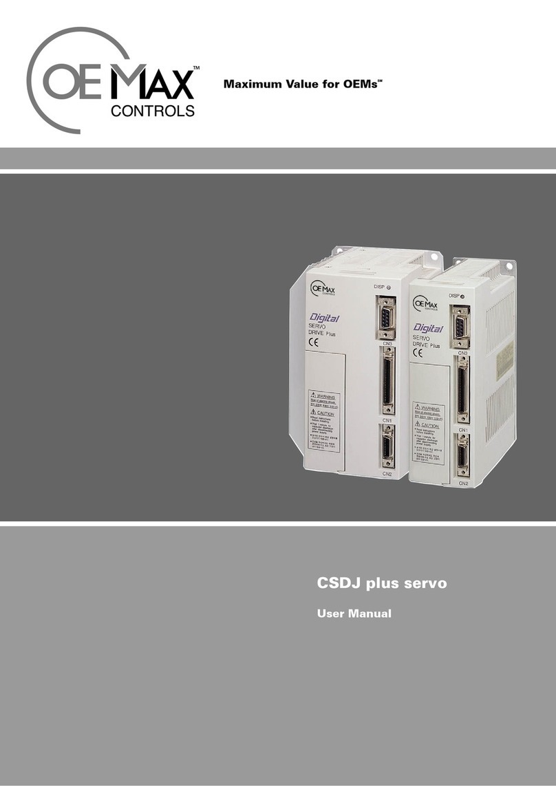
OE Max Controls CSDJ Plus User manual

Maximum Value for OEMsSM
CSDJ Plus Servo Drive
User Manual


Safety Precautions –
i
•Thank you for purchasing Rockwell Automation Korea CSDJ Plus Servo Drive.
•This user’s manual explains handling method, repair, inspection, error diagnosis,
troubleshooting and, specifications of the CSDJ Plus Servo Drive.
•Use the CSDJ Plus after completely understanding this user’s manual.
Precautions during Initial Setup
When setting up the product, select Encoder Type (SEt-51), Motor Type (SEt-52), Motor
Capacity (SEt-53), Control Mode (SEt-41) such as position, speed, and etc. after supplying the
power.
* After the change, turn off and on the power.
* For detailed information, refer to Chapter 5, Parameter Table.
Error such as Control Impossibility or Encoder Open Error may occur if the parameter selection
is incorrectly set as stated above.
General Precautions
This user’s manual may be changed without notice in case of product improvement or
specification change, or for better understanding of the manual.
Use the user’s manual included in the product purchased.
When re-ordering the user’s manual due to damage or loss, contact company agency or an agency
closeby recorded on the back of this manual.
Do not disassemble the servo drive. A/S is not provided for any accidents or damages caused
by the disassembly or modification of the servo drive by the user.

- CSDJ Plus Servo Drive User’s Manual
ii
Other Safety Precautions
• Install, operate, check and repair the product after reading and completely
understanding the user’s manual.
Also, use the product after sufficiently understanding the safety information or
surrounding specifications.
• After reading, make sure to keep the manual at an easy to reach place for
easy access.
• User’s manual records contents of safety specifications by categories of
Warning and Caution.
Warning
! : When handled incorrectly, dangerous situations may happen.
May cause severe or slight injuries, or cause only a product damage.
C
aution
: When handled incorrectly, dangerous situation (electro caution) may occur.
May cause death or severe injury.
• Even if the content is defined as , serious result may occur
depending on the situation. Make sure to follow the manual.
W
arning
!
Checking Product Status
Do not install the servo drive, which is damaged or has missing parts.
- It may cause injuries.
Warning
!
Precautions during Installation
Be careful in moving the product.
- Dropping on the foot may cause injuries.
Use nonflammable such as metals in locations to place servo drive.
- There may be a fire.
When installing several servos in one location, by installing cooling fans
and etc so the surrounding temperature is below 55℃.
- Overheating may cause fire or other accidents.
Warning
!

Safety Precautions –
iii
Precautions when Wiring
Operate only after checking that input power is off.
- There may be electric shock or fire.
Only the electrician should do the wiring.
- There may be electric shock or fire.
In case of wiring emergency stop circuit, check the operation after wiring
(Wiring responsibility is on the user.)
- There may be injuries.
Be sure to make the earth of grounding terminal. (Class 3 grounding)
- There may be electric shock or fire.
Warning
!
Cooling fin and electric discharge resistor overheats, so do not touch with
hands.
- It may cause burns.
It is easy to change the speed of servo drive from low to high, thus operate
after checking the motor and mechanical allowable limit.
- There may be injuries.
Do not check signal during the operation.
- The product may be damaged.
Each gain of this servo drive is properly set upon the delivery for the non-
load operation. When changing the setting, pay extra caution.
- The product may be damaged.
Warning
!

- CSDJ Plus Servo Drive User’s Manual
iv
Precautions when repairing
This servo drive has high voltage terminal, thus it is very dangerous.
Do not touch it.
- There may be electric shock.
Repair and check after sufficient amount of time has passed after cutting
off the main circuit power.
- It is dangerous because power flows in the capacitor.
Except for the people appointed, do not repair, check, nor replace the
parts.
- Before the operation, remove the metals (watch, ring, etc) from the body.
Operate after preparing the tools to handle insulation. There may be electric
shock.
C
aution
Control board uses C-MOS. Be aware when handling it.
- When touching with hand, the product may be damaged due to static electricity.
During being energized, do not exchange the wire or remove the connector
and etc.
- There may be injuries or damage in products.
C
aution
Do not modify the production.
- There may be electric shock or injuries.
C
aution

Contents - 1
Contents
Safety Precaution ·······························································································································
Chapter 1. Summary and Specifications ·························································································
1.1 Main Features of the Product ············································································································································
1.2 Preparation for the Servo Operation ································································································································
1.3 External View ·······································································································································································
1.4 Standard Specifications ························································································································································
Chapter 2. Installation and Wiring ··································································································
2.1 Check Items upon the Delivery of the Product ··············································································································
2.2 Precautions during Installation ···········································································································································
A. Installing the Servo Motor ············································································································································
B. Installing the Servo Drive ··············································································································································
2.3 External Terminal Block ·····················································································································································
2.4 Wiring ·····················································································································································································
A. Precautions when Wiring ··············································································································································
B. Wiring ················································································································································································
2.5 I/O Specification ··································································································································································
A. CN1 (I/0 Cable) ······························································································································································
B. CN2 (Connector for Encoder Connection) ················································································································
2.6 Noise Protection ···································································································································································
A. Precautions when Wiring ···············································································································································
B. Noise Filter ·······································································································································································
2.7 Circuit Breaker for Wiring ··················································································································································
Chapter 3. Startup and Adjustment ·······························································································
3.1 Check up Items prior to Start up ·····································································································································
A. Servo Motor ·····································································································································································
B. Servo Drive ······································································································································································
3.2 Startup ···················································································································································································
A. Power ON and OFF························································································································································
B. Check up Items prior to the Startup ·························································································································
C. Startup by the Operator ··············································································································································
D. Startup by I/O Input ··················································································································································
3.3 Autotuning ··········································································································································································
3.4 Test Run ·················································································································································································
Chapter 4. Using the Operator ········································································································
4.1 Operator ·················································································································································································
4.2 Types of Mode and Mode Switching ································································································································
4.3 Status Display Mode ····························································································································································
4.4 User Parameter Setting Mode ·············································································································································
4.5 Monitoring Mode ·································································································································································
4.6 System Parameter and Error Monitoring Mode ··············································································································
4.7 Jog Mode ················································································································································································
A. Operation by the Operator ···········································································································································
B. Autotuning ·····································································································································································
C. Auto Adjustment of Speed/Torque Command Offset ····························································································
D. Manual Adjustment of Speed/Torque Command Offset ························································································
E. Alarm Reset ·····································································································································································
F. D / A C o nv e r t e r Channel Selection ······························································· ································································
i
1-1
1-3
1-4
1-5
1-6
2-1
2-3
2-6
2-6
2-10
2-12
2-13
2-13
2-14
2-16
2-16
2-19
2-23
2-23
2-24
2-26
3-1
3-3
3-3
3-3
3-4
3-4
3-7
3-8
3-11
3-13
3-16
4-1
4-3
4-4
4-6
4-7
4-8
4-9
4-12
4-12
4-12
4-12
4-13
4-14
4-15

2 - CSDJ Plus Servo Drive User’s Manual
G. Output Adjustment Method of D/A Converter Channel ······················································································
H. Parameter Initialization ··················································································································································
I. Error History Clear ··························································································································································
J. Test Run ·············································································································································································
Chapter 5. Parameter List ···············································································································
5.1 User Parameter ····································································································································································
A. Motor and Encoder Setting ···········································································································································
B. Control Mode Setting ·····················································································································································
C. Parameter Related to AutoTuning ·······························································································································
D. Parameter Setting Related to Gain ······························································································································
E. Parameter Setting Related to Servo Control ·············································································································
F. Parameter Setting Related to Speed Control ·············································································································
G. Parameter Setting Related to Position Control ········································································································
H. Parameter Setting Related to Torque Control ··········································································································
I. Parameter Setting Related to Torque Limit ······························································· ···················································
J. Parameter Setting Related to Timing Control ·············································································································
K. Parameter Setting Related to D/A Output ·················································································································
5.2 Monitor Parameter List ·······················································································································································
5.3 Jog Mode Parameter List ·····················································································································································
5.4 Error Monitor and System Parameter List ·······················································································································
Chapter 6. Basic Functions ·············································································································
6.1 Speed Control ································································································································································
A. Speed Command ·····························································································································································
B. Multi Step Speed Control Mode ···································································································································
C. Speed/Multi Step Speed Control Mode ······················································································································
D. Manual Zero-Clamp Speed Control Mode ·················································································································
E. Auto Zero-Clamp Speed Control Mode ·····················································································································
F. Speed coincidence Output Signal ··································································································································
6.2 Changing the Motor Rotation Direction ··························································································································
6.3 Acceleration/Deceleration Time and S-Curve Operation ·····························································································
6.4 Selection of Stop Method ·················································································································································
A. Offset Adjustment ··························································································································································
B. Using the DB(Dynamic Brake) ·····································································································································
C. Using Zero-Clamp Function ·········································································································································
D. Emergency Stop ······························································································································································
6.5 Position Control ·····························································································································································
A. Wiring ···············································································································································································
B. Position Command Pulse Form ····································································································································
C. Electrical Specifications of Command Pulse ·············································································································
D. Position Counter Clear ···················································································································································
E. Position Completion Output Signal(----------
P-COM ) ········································································································
F. I/O Signal Timing ···························································································································································
G. Position/Speed Control Mode ······························································································································
6.6 Using Encoder Output ·······················································································································································
6.7 Electronic Gear ····································································································································································
6.8 Rotation Detection Output Signal ·····································································································································
6.9 Torque Control ·····································································································································································
A. Setting ···············································································································································································
B. Torque Command ···························································································································································
C. Limiting the Speed during the Torque Control ··········································································································
D. Position/Torque Control Mode ···························································································································
E. Torque Limit ····································································································································································
4-16
4-17
4-18
4-18
5-1
5-3
5-3
5-5
5-6
5-6
5-8
5-12
5-13
5-14
5-15
5-16
5-16
5-17
5-18
5-19
6-1
6-3
6-6
6-7
6-9
6-12
6-13
6-14
6-15
6-16
6-18
6-18
6-18
6-19
6-19
6-21
6-21
6-23
6-24
6-25
6-26
6-27
6-28
6-29
6-31
6-33
6-34
6-34
6-34
6-36
6-37
6-38

Contents - 3
6.10 Setting of Servo Drive Gain ············································································································································
6.11 Using Rotation Prohibition Function ·····························································································································
Chapter 7. Application of Other Functions ····················································································
7.1 Dynamic Brake ·····································································································································································
7.2 Brake Control ·································································································································································
7.3 Using an Absolute Encoder ················································································································································
A. Absolute Encoder Data Transmitting by Serial Interface ························································································
B. Absolute Encoder Reset ·················································································································································
C. Absolute Encoder Data Transmitting by switching of I/O port ············································································
7.4 Regeneration ··········································································································································································
A. Regenerative Energy ·······················································································································································
B. Allowable Load Inertia ···················································································································································
C. Vertical Load ····································································································································································
D. Regeneration Resistor ·····················································································································································
7.5 Setting of Motor Type and Capacity ·································································································································
7.6 Setting of Encoder Type (SEt-51) ·····································································································································
Chapter 8. Error Display and Troubleshooting ··············································································
8.1 Error Occurrence ·································································································································································
8.2 Alarm Output Signal ····························································································································································
8.3 Alarm Code and Troubleshooting ······························································· ······································································
Chapter 9. Repair and Checking ·····································································································
9.1 Servo Motor ··········································································································································································
9.2 Servo Drive ············································································································································································
9.3 Troubleshooting due to the Incorrect Wiring ·················································································································
9.4 Troubleshooting due to the Incorrect Setting ················································································································
9.5 Items to be Checked Prior to Asking for the Service ·····································································································
Appendix A. Motor Specification ····································································································
A.1 CSM Motor Specification ···················································································································································
A.2 CSMT Motor Specification ················································································································································
A.3 CSMR Motor Specification ················································································································································
A.4 CSMQ Motor Specification ···············································································································································
A.5 CSMZ Motor Specification ················································································································································
A.6 CSMD Motor Specification ···············································································································································
A.7 CSMF Motor Specification ················································································································································
A.8 CSMS Motor Specification ·················································································································································
A.9 CSMH Motor Specification ···············································································································································
A.10 CSMK Motor Specification ·············································································································································
A.11 Main Features of Each Motors ·······································································································································
Appendix B. External dimension of the Motor ·············································································
B.1 CSM Motor ·····································································································································································
B.2 CSMT Motor ··································································································································································
B.3 CSMR Motor ··································································································································································
B.4 CSMQ Motor ··································································································································································
B.5 CSMZ Motor ··································································································································································
B.6 CSMD/F/S/H/ Motor ·················································································································································
B.7 CSMK Motor ··································································································································································
Appendix C. Cable ··························································································································
C.1 Term Explanation ··························································································································································
C.2 Motor 3Phase Power Cable(CSM,CSMT/R/Z/Q ) ······································································································
C.3 Motor Brake Cable Assembly (CSM,CSMZ,CSMQ) ······························································· ····································
C.4 Motor 3 Phase Power Cable (CSMD,CSMF,CSMH,CSMS,CSMK) ·······································································
C.5 11 wire Incremental Encoder (CSMD,CSMF,CSMH,CSMS) ·····················································································
C.6 Absolute Encoder Cable Assembly (CSMD,CSMF,CSMH,CSMS) ·············································································
C.7 15 wire Incremental Encoder Cable Assembly (CSMD,CSMF,CSMH,CSMS,CSMK) ·············································
C.8 Motor Brake Cable(CSMD,CSMF,CSMH,CSMS,CSMK) ····························································································
6-42
6-45
7-1
7-3
7-4
7-8
7-8
7-10
7-11
7-15
7-15
7-16
7-17
7-18
7-19
7-21
8-1
8-3
8-4
8-5
9-1
9-3
9-4
9-5
9-6
9-7
A-1
A-1
A-5
A-8
A-10
A-13
A-16
A-20
A-23
A-26
A-29
A-32
B-1
B-1
B-4
B-5
B-6
B-7
B-8
B-12
C-1
C-1
C-2
C-3
C-4
C-5
C-6
C-7
C-8

4 - CSDJ Plus Servo Drive User’s Manual
C.3 Motor Brake Cable(CSM,CSMT/R/Z/Q) ······················································································································
C.4 Motor 3Phase Power Cable (CSMD/F/H/S/K) ······································································································
C.5 11Wire Incremental Encoder Cable(CSMD/F/H/S) ···································································································
C.6 Absolute Encoder Cable(CSMD/F/H/S) ·······················································································································
C.7 15Wire Incremental Encoder Cable(CSMD/F/H/S/K) ······························································································
C.8 Motor Brake Cable(CSMD/F/H/S/K) ···························································································································
C.9 User I/O Cable ····································································································································································
C.10 Compact Incremental Encoder Cable (CSM,CSMT/R/Z/Q) ··················································································
C.11 Absolute Encoder Cable(CSM,CSMT/R/Z/Q) ··········································································································
C.12 Communication Cable ·················································································································································
C.13 Connector Specification of Cable ···································································································································
C.14 Ordering Part Number ··················································································································································
Appendix D. Motor Connector ·······································································································
Appendix E. Load Calculation of the Mechanical Part ·································································
E.1 The Moment of Inertia Calculation ·································································································································
E.2 Roll Load ·········································································································································································
E.3 Timing Belt Load ···························································································································································
E.4 Ball Screw Load(Horizontal Axis) ·······························································································································
E.5 Ball Screw Load(Vertical Axis) ····································································································································
E.6 Rack & Pinion Load ······················································································································································
E.7 Round Plate Load ······················································································································································
Appendix F. Conversion Table of SI Unit and Conventional Unit ·················································
Appendix G. Motor Capacity Selection ··························································································
Appendix H. Revision Profile ·········································································································
C-3
C-4
C-5
C-6
C-7
C-8
C-9
C-10
C-12
C-14
C-15
C-16
D-1
E-1
E-1
E-2
E-4
E-6
E-8
E-10
E-12
F-1
G-1
H-1

Table of Contents - 1
Table of Contents
Chapter 1. Summary and Specifications
Table 1.1 Standard Specifications of CSDJ Plus Servo Drive ·····························································································
Table 1.2 Control Specifications ···············································································································································
Chapter 2. Installation and Wiring
Table 2.1 CSDJ Plus Rated Output and Applicable Motor ··································································································
Table 2.2 Allowable Load of the Motor ·································································································································
Table 2.3 Names of External Terminal Block of the CSDJ Plus ·······················································································
Table 2.4 I/O Specification of CN1 ·······································································································································
Table 2.5 I/O With Different Functions for Each Control Mode ·····················································································
Table 2.6 Connection of Encoder Connector ·······················································································································
Table 2.7 Recommended Noise Filter ·····································································································································
Table 2.8 Capacity of Circuit Breaker and Fuse ····················································································································
Chapter 3. Test Run and Adjustment
Table 3.1 LED Color and Description ···································································································································
Table 3.2 Setting the Torque Filter Cutoff Frequency (SEt-06) ·····················································································
Chapter 4. Using the Operator
Table 4.1 Types of Modes ························································································································································
Table 4.2 Content of Bit Data ···············································································································································
Table 4.3 Signal and Servo Status ············································································································································
Table 4.4 Monitor Type ······························································································································································
Table 4.5 Types of Error Saving Parameter ··························································································································
Table 4.6 Error Display of Operator and Trace Back Table ·····························································································
Table 4.7 Jog Mode Parameter ··················································································································································
Table 4.8 Parameter Value and Content of D/A Converter (USr-08) ·············································································
Table 4.9 Parameter Value and Content Related to D/A Converter Output ·································································
Chapter 5. Parameter Tables
Table 5.1 Encoder Types Setting (SEt-51) ······························································································································
Table 5.2 Motor Types Setting (SEt-52) ··································································································································
Table 5.3-A CSM/CSMZ/CSMQ/CSMP Motor Capacity Setting (SEt-53) ····································································
Table 5.3-B CSMD/CSMF/CSMH/CSMS/CSMN/CSMX/CSMK Motor Capacity Setting (SEt-53) ······················
Table 5.4 Monitor Parameter List ············································································································································
Table 5.5 Jog Mode Parameter List ··········································································································································
Table 5.6 Error Monitor and System Parameter List ············································································································
Chapter 6. Basic Functions
Table 6.1 Setting the Speed Control Mode ·····························································································································
Table 6.2 Using the P-CON signal ···········································································································································
Table 6.3 Multi Step Speed Control Mode Setting ················································································································
Table 6.4 Speed/Multi Step Speed Control Mode Setting ···································································································
Table 6.5 Step 4 Speed Usage Setting ······························································· ·······································································
Table 6.6 Manual Zero-Clamp Speed Control Setting ··········································································································
Table 6.7 Auto Zero-Clamp Speed Control Mode Setting ···································································································
Table 6.8 Effective Boundary of SEt-45 LED No.4 Setting ·······························································································
Table 6.9 Position Command Pulse Form (Set in SEt-46 LED No.1) ···············································································
Table 6.10 Electrical Specifications of Position Command Pulse ······················································································
Table 6.11 Setting of Position/Speed Control Mode ···········································································································
Table 6.12 Torque Command ···················································································································································
Table 6.13 Position/Torque Control Mode Setting ··················································································································
Table 6.14 Setting of Servo Drive Gain ·································································································································
1-6
1-7
2-4
2-9
2-12
2-16
2-18
2-19
2-24
2-26
3-4
3-14
4-4
4-6
4-6
4-8
4-9
4-11
4-12
4-15
4-16
5-3
5-3
5-4
5-4
5-17
5-18
5-19
6-3
6-4
6-7
6-9
6-10
6-12
6-13
6-15
6-23
6-24
6-28
6-34
6-37
6-42

2 - CSDJ Plus Servo Drive User’s Manual
Chapter 7. Application of Other Functions
Table 7.1 Brake Control Setting Parameter ·····························································································································
Table 7.2 Transmission Character of Absolute Encoder ·····································································································
Table 7.3 Allowable Load Inertia Ratio (When Regeneration Resistor is not connected and when operated at a rated speed) ·
Table 7.4 Regeneration Resistor ···············································································································································
Table 7.5 Setting of CSM/P/Q/Z Motor Capacity (SEt-53) ······························································································
Table 7.6 Setting of CSMD/S/F/H/N/X/K Motor Capacity (Set-53) ······························································· ············
Table 7.7 Setting of Encoder Type ··········································································································································
Chapter 8. Error Display and Troubleshooting
Table 8.1 Alarm Related Input/Output Terminal ·················································································································
Table 8.2 Alarm Detect Type ····················································································································································
Table 8.3 Error Display and Troubleshooting ·······················································································································
Chapter 9. Repair and Checking
Table 9.1 Check, Repair and Cleaning Method ······················································································································
Table 9.2 Maintaining, Repair, and Check Method of Servo Motor ··················································································
Appendix
Table A.1 CSM Motor Specification ····································································································································
Table A.2 CSM Motor Brake Specification ·························································································································
Table A.3 CSM Motor Specification (When reducer is attached) ·······················································································
Table A.4 CSMT Motor Specification ·································································································································
Table A.5 CSMT Motor Brake Specification ··························································································································
Table A.6 CSMR Motor Specification ·································································································································
Table A.7 CSMR Motor Brake Specification ··························································································································
Table A.8 CSMQ Motor Specification ·································································································································
Table A.9 CSMQ Motor Brake Specification ······················································································································
Table A.10 CSMZ Motor Specification ·································································································································
Table A.11 CSMZ Motor Brake Specification ·······················································································································
Table A.12 CSMD Motor Specification ··································································································································
Table A.13 CSMD Motor Brake Specification ·······················································································································
Table A.14 CSMF Motor Specification ···································································································································
Table A.15 CSMF Motor Brake Specification ························································································································
Table A.16 CSMS Motor Specification ····································································································································
Table A.17 CSMS Motor Brake Specification ·····················································································································
Table A.18 CSMH Motor Specification ·······························································································································
Table A.19 CSMH Motor Brake Specification ·······················································································································
Table A.20 CSMK Motor Specification ··································································································································
Table A.21 CSMK Motor Brake Specification ····················································································································
Table F.1 Unit Conversion ·····················································································································································
7-4
7-9
7-12
7-14
7-15
7-16
7-17
8-4
8-5
8-6
9-3
9-4
A-1
A-2
A-5
A-5
A-6
A-8
A-9
A-10
A-11
A-13
A-14
A-16
A-17
A-20
A-21
A-23
A-24
A-26
A-27
A-29
A-30
F-1

List of Figures
- 1
List of Figures
Chapter 1. Summary and Specifications
Fig 1.1 Preparation for Operation ············································································································································
Fig 1.2 Outline Dimension (CSDJ-A3C,A5C,01B,02B,04B) ································································································
Fig 1.3 Outline Dimension (CSDJ-02C,06B,10B) ·················································································································
Chapter 2. Installation and Wiring
Fig 2.1 Drive Display ··································································································································································
Fig 2.2 Reducer Display ·····························································································································································
Fig 2.3 Motor Type Display ······························································································································ ························
Fig 2.4 AC Servo Motor ····························································································································································
Fig 2.5 Coupling ··········································································································································································
Fig 2.6 Installation of Servo Drive (Wall Mounting Type) ··································································································
Fig 2.7 Installation of Servo Drive (Installing in the Panel) ································································································
Fig 2.8 Connection of External Terminal Block ···················································································································
Fig 2.9 Wiring ··············································································································································································
Fig 2.10 Example of Wiring in Main Circuit ······················································································································
Fig 2.11 9 Wire Incremental Encoder Connection Method Of CSM/CSMG,P,T,R Motor ·······································
(Setting Value of SEt-51 = 1 Refer to 7.6)
Fig 2.12 Absolute Encoder Connection Method of CSM/CSMG,P,T,R Motor ······························································
(Setting value of SEt-51 = 2 Refer to 7.6)
Fig 2.13 CSMD/F/H/S Motor and 11 Wire Incremental Encoder Connection Method ··············································
(When the setting value of SEt-51 is 100)
Fig 2.14 CSMD/F/S/H/N/X/K Motor and 15 Wire Incremental Encoder Connection Method ·····························
(When the setting value of SEt-51 is 101, 102, 106, 300~307)
Fig 2.15 Absolute Encoder Connection Method of CSMQ/Z Motor ··············································································
(Setting value of SEt-51= 104, 105 Refer to 7.6)
Fig 2.16 Shape and PIN Number of CN2(Encoder Connector) ························································································
Fig 2.17 Grounding and Noise Filter for Noise Reduction ································································································
Chapter 3. Start up and Adjustment
Fig 3.1 Example of Power ON and OFF································································································································
Fig 3.2 Power Supply Method for Multi-Servo Drive Connection ·····················································································
Fig 3.3 Setting the Jog Operation Speed ·································································································································
Fig 3.4 Setting Acceleration and Deceleration Time ·············································································································
Fig 3.5 Startup by the Operator ················································································································································
Fig 3.6 Servo ON·········································································································································································
Fig 3.7 Speed Command Analog Input ···································································································································
Fig 3.8 Autotuning Procedure ················································································································································
Fig 3.9 Example of Auto Tuning by the Operator ·············································································································
Fig 3.10 Operation Pattern of the Test Run ··························································································································
Fig 3.11 Test Run Using the Operator ···································································································································
Chapter 4. Using the Operator
Fig 4.1 Operator ··········································································································································································
Fig 4.2 Mode Switching ·····························································································································································
Fig 4.3 Status Display Mode ······················································································································································
Fig 4.4 Example of Setting User Parameter ···························································································································
Fig 4.5 Example of Parameter of Monitoring Mode ·········································································································
Fig 4.6 Display of Con-12(V/P: Speed/Positioning Completion Signal CN1 Pin 41-42) ·············································
Fig 4.7 Example of Error ························································································································································
Fig 4.8 Speed/Torque Command Input ··································································································································
1-4
1-5
1-5
2-3
2-3
2-5
2-6
2-7
2-10
2-10
2-12
2-14
2-15
2-20
2-20
2-21
2-21
2-22
2-22
2-24
3-4
3-6
3-8
3-9
3-10
3-11
3-12
3-13
3-14
3-16
3-16
4-3
4-5
4-6
4-7
4-8
4-8
4-9
4-13

2 - CSDJ Plus Servo Drive User’s Manual
Fig 4.9 Auto Adjustment of Speed Command offset ··········································································································
(In case of auto adjustment of torque command offset, “Au-tC”is displayed.)
Fig 4.10 Manual Adjustment of Speed Command offset ···································································································
(In case of the manual adjustment of torque command offset , " Co-tC" is displayed.)
Fig 4.11 Alarm Reset ··································································································································································
Fig 4.12 Example of Selecting the D/A Channel Output Content ·················································································
Fig 4.13 Initialization of User Parameter ·······························································································································
Fig 4.14 Error History Clear ·····················································································································································
Chapter 5. Parameter Tables
Fig 5.1 I/O Status of Con-12 (V/P: Speed/Position Completion Signal CN1 pin 41-42) ············································
Chapter 6. Basic Functions
Fig 6.1 Using the ---------
P-CON Signal ···········································································································································
Fig 6.2 Example of P/PI Control Conversion Usage ··········································································································
Fig 6.3 Analog Speed Command Input Circuit ······················································································································
Fig 6.4 Analog Input Voltage and Speed ·································································································································
Fig 6.5 Multi Step Speed Control Circuit ································································································································
Fig 6.6 Multi Step Speed Operation ·········································································································································
Fig 6.7 Using the Step 4 Speed ·················································································································································
Fig 6.8 Example of Step 4 Speed Command Usage ·············································································································
Fig 6.9 Using the Zero-Clamp Speed Control ················································································································
Fig 6.10 Zero-Clamp Operation ···············································································································································
Fig 6.11 Width of Speed Coincidence Output Signal ···········································································································
Fig 6.12 Inner Speed Command Generation ·························································································································
Fig 6.13 Definition of Acceleration/Deceleration Time ·····································································································
Fig 6.14 Selection of Stop Method ··········································································································································
Fig 6.15 Emergency Stop ···························································································································································
Fig 6.16 Selection of Stopping Method by Emergency Stop and Error Occurrence ······················································
Fig 6.17 Position Command Input Terminal ··························································································································
Fig 6.18 Wiring for Position Command of Line Drive Output ··························································································
Fig 6.19 Wiring for Position Command of Open Collector Output ··················································································
Fig 6.20 ---------
P-CLR Signal Usage ··················································································································································
Fig 6.21 Output Width of Position completion Signal ······························································· ········································
Fig 6.22 I/O Signal Timing Chart ············································································································································
Fig 6.23 Using the Encoder Output Signal ·····························································································································
Fig 6.24 Example of Wiring between Incremental Encoder Output and Host Controller ············································
Fig 6.25 Encoder Output Pulse Form ·····································································································································
Fig 6.26 Example of Electronic Gear Setting (Ball Screw) ··································································································
Fig 6.27 Example of Electronic Gear Setting (Belt +Pulley) ······························································································
Fig 6.28 Example of Electronic Gear Setting (Turn Table) ································································································
Fig 6.29 Block Diagram of Electronic Gear ··························································································································
Fig 6.30 Rotation Detection Output Signal ····························································································································
Fig 6.31 Input Voltage and Command Torque ······················································································································
Fig 6.32 Torque Command Input Circuit ·······························································································································
Fig 6.33 External Torque Limit Command and Torque Limit Detection Output Signal ················································
Fig 6.34 Gain Tuning ·································································································································································
Fig 6.35 Using the Rotation Prohibition Input Signal ··········································································································
Chapter 7. Application of Other Functions
Fig 7.1 Dynamic Brake ·······························································································································································
Fig 7.2 Timing Chart of Servo OFF Input Signal and Brake Control Output Signal ·····················································
Fig 7.3 Timing Chart of Brake Control Signal when the Motor is Stopped During the Rotation ································
Fig 7.4 Timing Chart Brake Control Signal at Servo ON ····································································································
4-13
4-14
4-14
4-15
4-17
4-18
5-17
6-4
6-5
6-6
6-6
6-7
6-8
6-10
6-11
6-12
6-13
6-14
6-16
6-16
6-18
6-20
6-20
6-21
6-22
6-22
6-25
6-26
6-27
6-29
6-29
6-30
6-31
6-31
6-32
6-32
6-33
6-35
6-35
6-40
6-44
6-45
7-3
7-5
7-5
7-6

List of Figures
- 3
Fig 7.5 Using Brake Relay ··························································································································································
Fig 7.6 Wiring With the Host Controller when Absolute Encoder is used ····································································
Fig 7.7 Regenerative Energy ······························································································································ ·······················
Fig 7.8 Operation Pattern of Vertical Load ····························································································································
Fig 7.9 Regeneration Resistor and Regeneration Unit Connection ····················································································
Fig 7.10 Setting of Motor Type (SEt-52) ································································································································
Chapter 8. Error Display and Troubleshooting
Fig 8.1 Error Occurrence ··························································································································································
Fig 8.2 Connection Diagram of Alarm Related Output Signal ···························································································
7-6
7-8
7-11
7-13
7-14
7-15
8-3
8-4

4 - CSDJ Plus Servo Drive User’s Manual
MEMO

Chapter 1. Summary and Specifications 1 - 1
Chapter 1
Summary and Specifications
Chapter 1 explains about the basic information on complete composition
and standard specifications of CSDJ Plus Servo Drive.
1.1 Main Features of the Product
1.2 Preparation for the Servo Operation
1.3 External View
1.4 Standard Specifications

1 - 2 CSDJ Plus Servo Drive User’s Manual
MEMO

Chapter 1. Summary and Specifications 1 - 3
1.1 Main Features of the Product
CSDJ Plus Servo Drive is an AC servo motor drive with full digital method, where high speed and
precision control is possible, using 32 bit high speed DSP. Also, position control mode, speed
control mode, torque control mode, and etc are provided so that the Drive can be used according
to the needs and provides various types of I/O input and output. CSDJ Plus Servo Drive can
provide the best control in its performance and function.
Main features of the CSDJ Plus Servo Drive are as follows:
•Full digital control with high speed and accuracy is achieved by using the 32bit high speed
DSP.
•Optimized the size by designing the servomotor to be 1/3 and the drive to be 1/5 of the
previous model. Normal Incremental (15 lines), Brief incremental (11,9 lines) and
Absolute (15 lines) Encoder are added to this product for easier system design.
•It also includes the autotuning function, which allows the beginners to easily operate the
system.
Speed
After autotuning
Before autotuning
Speed
Time Time
•The highly accurate control is possible with speed control range of 1:3000.
•With the various built-in functions such as compatibility with the PC S/W, it can be used in
various ranges of applications.
Servo Driver
PC Motor
Do not disassemble the servo drive. A/S is not provided for any accidents or
damages caused by the disassembly or modification of the servo drive by the
user.
Warning
!

1 - 4 CSDJ Plus Servo Drive User’s Manual
1.2 Preparation for Servo Operation
The block description below is the basic steps before operating the servo drive.
Motor Power and PE Connection
AC power, PE Connection
Parameter Setting and Gain adjustment
Startup
I/O Connection (CN1)
Encoder Cable Connection (CN2)
Check the encoder type
(
SEt-
51), motor type (SEt-52
)
and
motor capacity (SEt-53
)
before
the start up.
Fig 1.1 Preparation for Operation
Other manuals for CSDJ Plus
2
This manual suits for next models
15
Table of contents
Other OE Max Controls Servo Drive manuals