OEM PDD-300 User manual

1
rev 1.27 / 2021 07 14
PDD-300 pulsed diode driver
User manual
Warning! This equipment may be dangerous.
Please read user manual before starting operations.
Important note. Please measure output with adequate load only (diodes). Resistive load
connected to the output won’t destroy the driver, but will severe distort its behavior.

2
Table of content
WARNINGS ............................................................................................................................3
EXPLANATION OF SYMBOLS ....................................................................................................3
OVERVIEW / APPLICATIONS.....................................................................................................4
COOLING ...............................................................................................................................4
APPEARANCE / LAYOUT...........................................................................................................4
CONNECTORS / PINS / INTERFACE SIGNALS..............................................................................5
INSTALLATION........................................................................................................................7
OPERATIONS NOTES ...............................................................................................................7
TROUBLESHOOTING ...............................................................................................................7
INPUT FUSES ..........................................................................................................................7
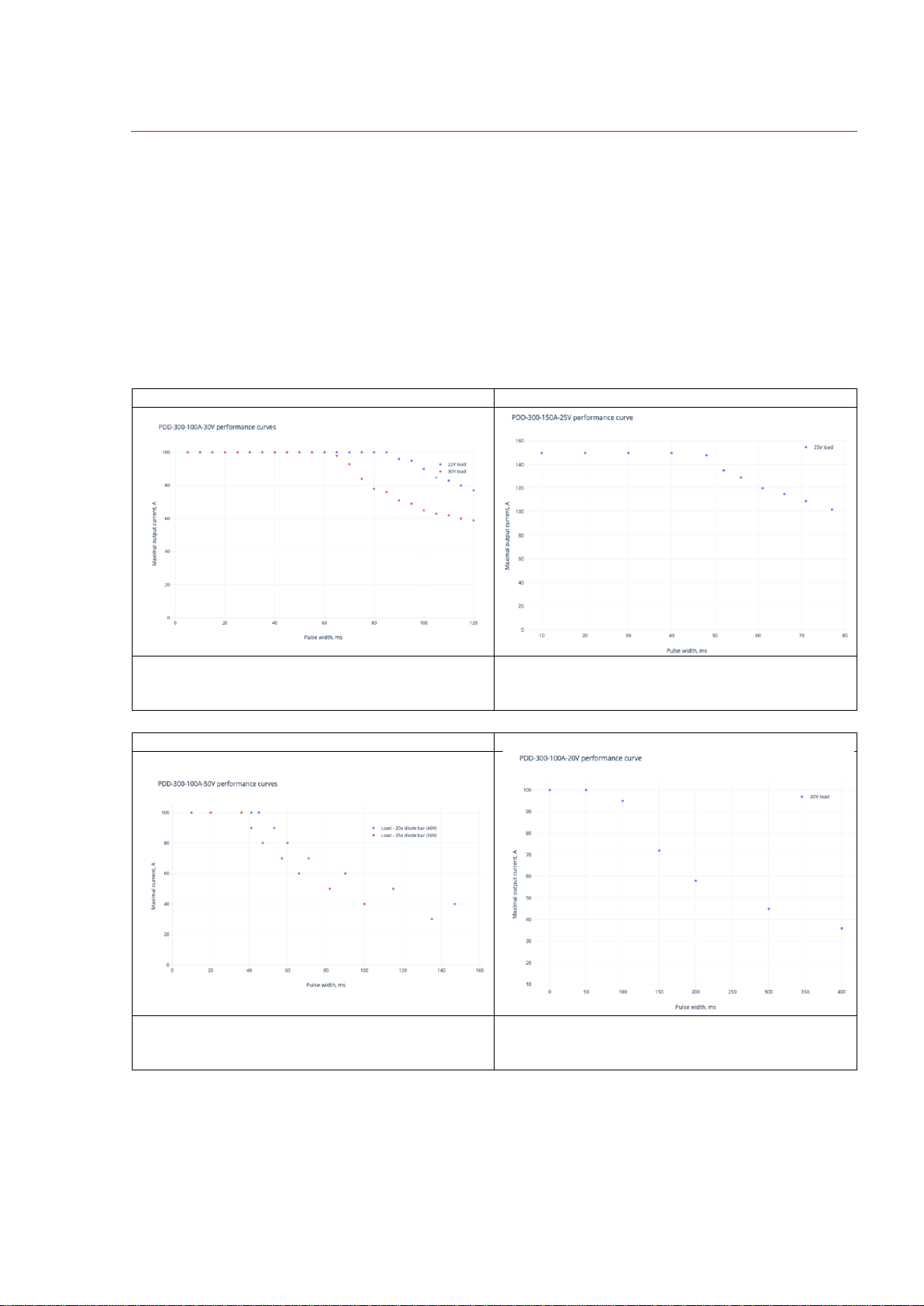
PULSE WIDTH LIMITATIONS ....................................................................................................8
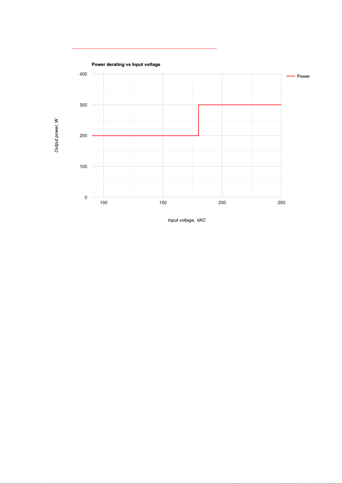
SPECIFICATIONS .....................................................................................................................9
DIMENSIONAL DRAWING (STANDARD VERSION).....................................................................11
DIMENSIONAL DRAWING (LONG PULSE VERSION) ..................................................................12
HOW TO ORDER? .................................................................................................................13
ENVIRONMENTAL PROTECTION.............................................................................................13
NAME AND ADDRESS OF THE MANUFACTURER......................................................................13
ELECTROMAGNETIC ENVIRONMENT –GUIDANCE ..................................................................14

3
Warnings
Warning! The equipment is CLASS I ME EQUIPMENT.
To avoid risk of electrical shock, the equipment must be
protectively grounded.
Warning! There is no user-serviceable parts inside the device.
Do not self-repair the driver. Do not even open the enclosure, because
of electrical shock risk with residual high voltage.
Warning! Equipment is not suitable for use in presence of a
flammable anesthetic mixture with air or with oxygen or nitrous oxide.
Explanation of symbols
Symbol
Description
Refer to instruction manual before handling
IPX0
Particles: No data available to specify a protection rating
Water: Non-protected
Dangerous voltage
Direct current
Protective earth terminal
The product shall not be disposed of with household waste
The year and the month of the manufacturing
The name and the address of the manufacturer
MAINS
AC power input of the device
LED +
LED -
Output positive and output negative of the device
INTERFACE
Interface (control) connector of the device

4
Overview / Applications
PDD-300 is a series of high-power pulsed diode drivers. Peak output power is up to 5kW
(with user selectable IMAX and VMAX), averaged output power is up to 300W.
Driver was specially designed for direct diode hair removal application.
Driver’s input is 100-240VAC.
Cooling
The module contains a fan for active cooling. No additional cooling is required.
Appearance / Layout

5
Connectors / Pins / Interface signals
INTERFACE: 15-pin D-SUB Female
PIN (color)
DESIGNATION
DESCRIPTION
1 (green)
ENABLE
+5V TTL applied to this pin enable PDD.
While 0V are applied to this pin or pin is
unconnected module is disabled.
Once Fault has occurred module is
blocked till you eliminate fault cause, then
disable module and enable it again.
2 (orange)
FAULT
If module is enabled and some trouble has
occurred, module automatically stops
operations and sets Fault status (Fault
loop is “closed”).
Fault can be caused by following
reasons:
- overheating
- mains voltage interruption
- maximum pulse energy exceeded
To remove Fault state one should disable
driver and enable it again
In case of normal operations Fault loop is
“opened”.
Maximum allowed current in Fault loop is
50mA.
3 (transparent)
PULSE 1
+5V TTL pulse should be applied to pin 3
and to pin 8 simultaneously in order to
obtain pulsed current from PDD-300.
In cases if 0V is applied to one of these
pins or at least one of these pins is
unconnected, there will be no current
from PDD-300.
4 (black)
PULSE 2 RETURN
Return of Pulse 2 signal
5 (yellow)
PULSE 1 RETURN
Return of Pulse 1 signal
6
N/C
7 (blue)
CURRENT
PROGRAM
Voltage applied to this pin sets output
current.
0-10V DC are linear with 0-IMAX.
8 (white)
PULSE 2
+5V TTL pulse should be applied to pin 3
and to pin 8 simultaneously in order to
obtain pulsed current from PDD-300.
In cases if 0V is applied to one of these
pins or at least one of these pins is
unconnected, there will be no current from
PDD-300.
9 (purple)
ENABLE
RETURN
Return of Enable signal
10, 11, 12, 13
N/C

6
14 (red)
+15V DC
AUXILIARY
OUTPUT
Auxiliary +15V DC output.
Maximum output current 50mA.
15 (white/blue)
INTERFACE
RETURN
Return of other Interface signals (namely
Fault, Current program and +15V DC)
AC POWER INPUT: Molex Minifit MF-6F type
123
6 45
PIN (color)
DESCRIPTION
1, 4
Pins 1 and 4 are interconnected inside the module
2, 5
Not used
3, 6
Pins 3 and 6 are interconnected inside the module
OUTPUT POSITIVE AND OUTPUT NEGATIVE:
M6 thread (8mm thread depth)
PIN (color)
DESCRIPTION
DIODE “+” (red)
To laser diode anode
DIODE “–” (black)
To laser diode cathode
GROUND: M5 stud
Module should be grounded using this stud.
Grounding should be done before powering the system.
Grounding policy
By default OUTPUT POSITIVE and OUTPUT NEGATIVE
are isolated from the chassis’ ground (i.e. output is floating).
Modifications with grounded anode or grounded cathode
are available upon request.

7
Installation
•Only qualified personnel is allowed install and perform the connection of PDD-300 into
customer’s system
•PDD-300 is intended only for diode driving applications. The module should only be
used inside the medical equipment, which has means to isolate its circuits electrically
from the supply mains on all poles simultaneously
•Use four M4 mounting slits on the bottom side of PDD-300 to fix the module in your
system. Refer to the Dimensional drawing section for their location
•There is no preferred driver orientation, it can be mounted in normal position, upside-
down position or in other orientations, as well
•Connect the module to your system protective ground using provided M5 grounding stud
•Connect AC INPUT, OUTPUT and INTERFACE cables according to their functions
•Since module is air cooled, at least 50mm of free space should be provided both at the
suction and pressure sides of PDD-300
Operations notes
1. The proper sequence of driver's start up procedure is 'power -> enable -> pulse'. Other
sequences are considered as incorrect
2. When driver is powered but disabled, the fan rotates slowly;
once driver is enabled, the fan will accelerate to a higher speed
3. Fault state is set when fault condition is met AND driver is enabled
4. To remove Fault state one should disable driver and enable it again
Troubleshooting
•In case of a mains voltage interruption, the output voltage drops down. Once the mains
voltage is restored, the unit doesn’t restart automatically and needs to be enabled again to
resume the operations.
Input fuses
Designation
Type
Parameters
Suggested p/n
FU1, FU2
Fast (quick acting)
High breaking capacity
Dimensions: 5x20 mm
Voltage rating: 250 VAC
Current rating: 10 A
Schurter 0001.1014

8
Pulse width limitations
Maximum pulse width, which the driver is able to provide at its output, isn’t fixed, but depends
on driver’s modification, operating current, load voltage and input voltage.
Approximate formulae to estimate the maximum pulse width in a certain regime is
EMAX=I*V*TMAX, where TMAX is a maximum pulse width PDD-300 is able to provide with
current I and voltage V at its output. EMAX is a maximum extractable energy, which varies from
~200J in standard modifications to ~300J in long pulse modifications.
Examples of pulse width curves for different drivers and different loads are given below. More
detailed information can be requested from the manufacturer.
PDD-300-100A-30V
PDD-300-150A-25V
Maximum pulse width - around 65ms at maximum
current and voltage. Even longer at smaller currents
and/or voltages
Maximum pulse width - around 45ms at maximum
current and voltage. Even longer at smaller currents
and/or voltages
PDD-300-100A-50V
PDD-300-100A-20V
Maximum pulse width - around 35ms at maximum
current and voltage. Even longer at smaller currents
and/or voltages.
Maximum pulse width - around 100ms at maximum
current and voltage. Even longer at smaller currents
and/or voltages.

9
Specifications
ELECTRICAL
INPUTS
Input voltage
100-240VAC 50/60Hz
Input current
<5A, inrush current <10A
OUTPUT
Maximum output voltage
(VMAX) *
Up to 50V (user selectable)
Maximum output current
(IMAX) *
Up to 200A (user selectable)
Peak power *
Up to 5kW
(*) IMAX * VMAX shouldn’t exceed maximum peak power (5kW)
Minimum pulse width
1ms (limited with rise and fall times)
Maximum pulse width **
From tens to hundreds of milliseconds
(depends on driver’s modification,
operating current and voltage, see also
Pulse width limitations section)
Maximum pulse energy
(EMAX) **
~200J in standard version (up to ~250J
on request)
~300J in long pulse version
(**) In given regime, i.e. with given operating current (I), voltage (V) and
pulse width (t), pulse energy (E) can be calculated as E=I*V*t. Since internal
buffer capacitance of PDD-300 is limited, pulse energy is also limited (E <
EMAX). Please contact the factory for further details.
Rise and fall times
<1ms (10-90% level)
Average output power
200W for 90-180VAC input
300W for 180-264VAC input
Output power deratings
See next page
Pulse repetition rate
Limited with pulse energy and
maximum averaged power only
Current accuracy
<1% of IMAX
Current overshoot
<1% of IMAX
SAFETY
Safety as per IEC 60601-1
EMC as per IEC 60601-1-2
COOLING
No external cooling is required
ENVIRONMENT
Atmospheric pressure
70 kPa to 106 kPa
Operation temperature
0 … +40 °C (see also derating curves)
Storage temperature
-20 … +60 °C
Humidity
90%, non-condensing
MECHANICAL
Dimensions
See dimensional drawings below
Weigth
Approx. 2.8 kg

10
OUTPUT POWER DERATINGS
Ambient temperature –40 °C

11
Dimensional drawing (standard version)

12
Dimensional drawing (long pulse version)

13
How to order?
PDD-300-XX-YY-[LP], where
XX means maximum output current IMAX (user selectable up to 200A, even higher current is
available on special request)
YY means maximum output voltage VMAX (user selectable up to 50V, other on request)
[LP] means optional long pulse modification (see also Pulse width limitations section to better
understand the driver’s performance).
Examples (some popular modifications):
P/N
Description
Certificates
PDD-300-100A-30V
100-240VAC input, 100A/30V output, standard version
maximum pulse width >65ms @ 100A, 30V, 230VAC
IEC 60601-1:2005 +
A1: 2012
IEC 60601-1-2:2014
PDD-300-150A-25V
100-240VAC input, 150A/25V output, standard version
maximum pulse width >45ms @ 150A, 25V, 230VAC
PDD-300-100A-30V-LP
100-240VAC input, 100A/30V output, long pulse version
maximum pulse width >100ms @ 100A, 30V, 230VAC
On demand
PDD-300-150A-25V-LP
100-240VAC input, 150A/25V output, long pulse version
maximum pulse width >65ms @ 150A, 25V, 230VAC
On demand
Other modifications are available upon request.
Cables are ordered and purchased separately.
PDD-300-CABLES
A set of cables for PDD-300. Includes:
- AC input cable –1pc
- Interface cable –1pc
- Output leads –2pc
-
Environmental protection
PDD-300 should not be disposed of with household waste.
Please dispose PDD-300 in accordance with the legislation on the management of electronic
waste in your country.
Name and address of the manufacturer
OEM Tech O.O.O.
Odoevskogo 129
220018 Minsk, Belarus

14
Electromagnetic environment –Guidance
Standard: IEC 60601-1-2:2014
Environment of intended uses: Professional Healthcare Facility Environment
Emission test
Limit
Electromagnetic environment - Guidance
Conducted emission
CISPR 11, Group 1, Class A
Device uses RF energy only for its internal function.
Therefore, its RF emissions are very low and are not
likely to cause any interference in nearby electronic
equipment.
Radiated emission
CISPR 11, Group 1, Class A
Harmonic current emissions
IEC 61000-3-2, Class A
Device is directly connected to the public low-voltage
power supply network that supplies buildings used for
domestic purposes.
Voltage fluctuations and flicker
IEC 61000-3-3
Immunity test
Compliance level
Electromagnetic environment - Guidance
Electrostatic Discharge
(IEC 61000-4-2)
Contact Discharge: ±8 kV
Air Discharge: ±2 kV, ±4 kV,
±8 kV, ±15 kV
Floors should be wood, concrete or ceramic tile. If
floors are covered with synthetic material, the relative
humidity should be at least 30%.
Radiated RF EM filed
(IEC 61000-4-3)
80-2700 MHz; 1kHz AM 80 %;
3 V/m
Portable and mobile RF communications equipment
should be used no closer to any part of the device,
including cables, than the recommended separation
distance calculated from the equation applicable to the
frequency of the transmitter.
Recommended separation distance:
d = 1.2√P for 80 MHz to 800 MHz
d = 2.3√P for 800 MHz to 2,7 GHz
where P is the maximum output power rating of the
transmitter in watts (W) according to the transmitter
manufacturer and d is the recommended separation
distance in meters (m).
Proximity fields form RF
wireless communications
equipment (IEC 61000-4-3)
385 MHz; Pulse Modulation: 18
Hz; 27 V/m
450 MHz, FM + 5 Hz deviation:
1 kHz sine; 28 V/m
710, 745, 780 MHz; Pulse
Modulation: 217 Hz; 9 V/m
810, 870, 930 MHz; Pulse
Modulation: 18 Hz; 28 V/m
1720, 1845, 1970 MHz; Pulse
Modulation: 217 Hz; 28 V/m
2450 MHz; Pulse Modulation:
217 Hz; 28 V/m;
5240, 5500, 5785 MHz; Pulse
Modulation: 217 Hz; 9 V/m
Portable and mobile RF communications equipment
should be used no closer to any part of the device,
including cables, than the recommended separation
distance 30 cm.
Electrical fast transients / bursts
(IEC 61000-4-4)
Power lines: 2 kV; 100 kHz
repetition frequency
Signal lines: 1 kV; 100 kHz
repetition frequency
Mains power quality should be that of a typical
environment.
Surges (IEC 61000-4-5)
L-N: 1kV at 0°, 90°, 180°, 270°
L-PE, N-PE: 2 kV at 0°, 90°,
180°, 270°
Mains power quality should be that of a typical
environment.
Conducted disturbances
inducted by RF fields
(IEC 61000-4-6)
0.15-80 MHz; 1kHz AM 80 %;
3 Vrms, 6 Vrms in ISM
Portable and mobile RF communications equipment
should be used no closer to any part of the device,
including cables, than the recommended separation
distance calculated from the equation applicable to the
frequency of the transmitter.

15
Recommended separation distance:
d = 1.2√P for 150 kHz to 80MHz
where P is the maximum output power rating of the
transmitter in watts (W) according to the transmitter
manufacturer and d is the recommended separation
distance in meters (m).
Rated power frequency
magnetic fields (IEC 61000-4-8)
30 A/m, 50 Hz
Power frequency magnetic fields should be at levels
characteristic of a typical location in a typical
commercial or hospital environment.
Voltage dips / Voltage
interruptions (IEC 61000-4-11)
0% UTfor 0.5 cycle at 0°, 45°,
90°, 135°, 180°, 225°, 270°,
315°
0% UTfor 1 cycle at 0°
70% UTfor 25/30 cycles at 0°
0% UTfor 250/300 cycles 0°
Mains power quality should be that of a typical
environment. If the user of the device requires
continued operation during power mains interruptions,
it is recommended that the device is powered from an
uninterruptible power supply or battery.
Table of contents