ohmex SONARMITE v3.0 User manual

SonarMite v3.0 (c)2009 Lymtech LLC
Page 1 6/13/2009
SONARMITE v3.0
PORTABLE BLUETOOTH ECHO SOUNDER
Ohmex is a company formed to manufacture and distribute products designed by Lymtech LLC, a company founded on
technological innovation and design. The company prides itself on being the first to produce products in the field of
instrumentation and software used within the Earth Science sectors. Achievements to date include DGM ,the first digital ground
modelling software to run a standard PC, SONARMITE, the first truly portable echo sounder, TIDALITE the first portable Tide
Gauge, EDAS, Integrated tide and weather networked software for use by ports and harbours. WinSTRUMENTATION - The
integration of Instrumentation, Wireless networks and modern portable computer equipment.

SonarMite v3.0 (c)2009 Lymtech LLC
Page 2 6/13/2009
Contents
SONARMITE v3.0........................................................................................................1
PORTABLE BLUETOOTH ECHO SOUNDER......................................................1
INTRODUCTION .........................................................................................................3
Typical Use of the Equipment ...................................................................................4
Equipment Supplied...................................................................................................5
INSTALLATION & USE..............................................................................................6
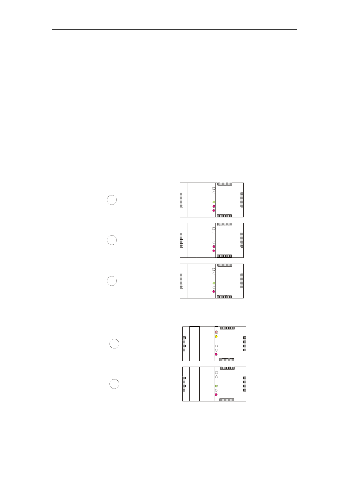
Switching the System On...........................................................................................6
Data Collection Techniques.......................................................................................6
Barchecking ...............................................................................................................6
Internal Battery Charging ..........................................................................................7
Reverse Voltage Protection........................................................................................8
Weatherproofing........................................................................................................8
DEPTH TRANSDUCER...............................................................................................9
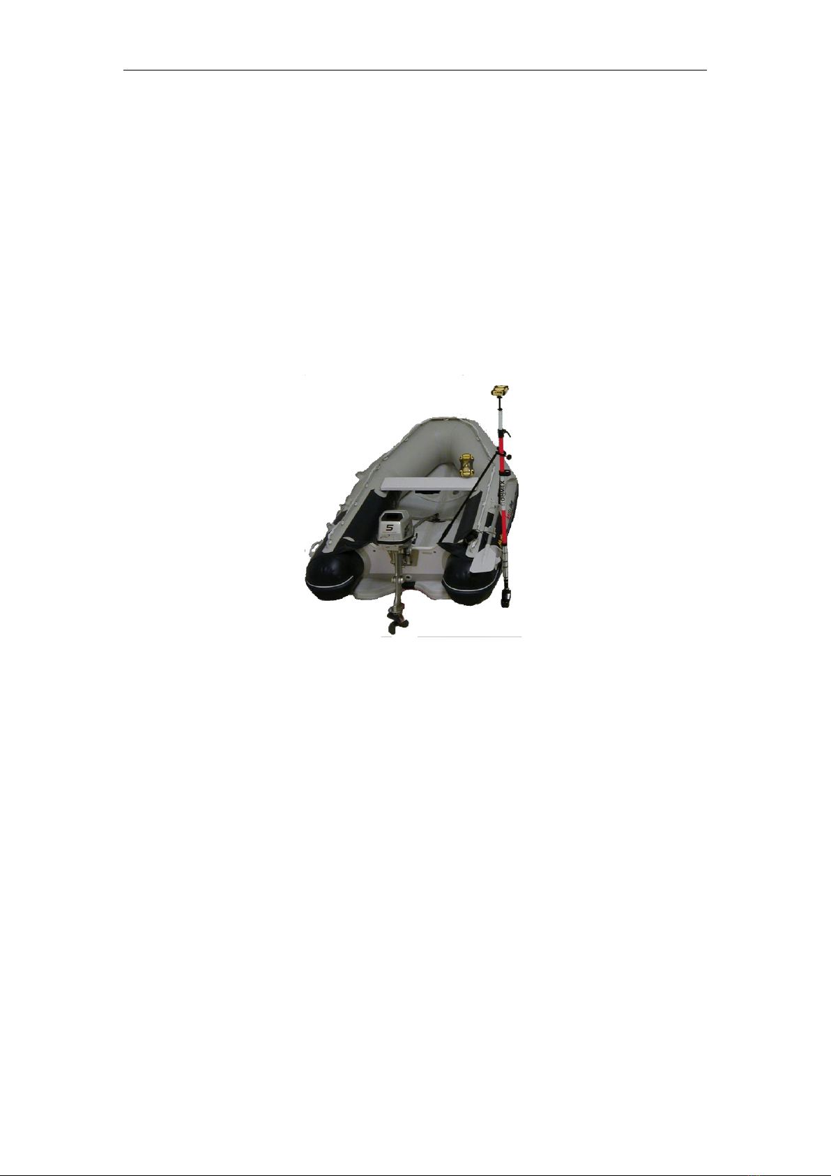
Transducer Mounting.................................................................................................9
Avoid Stressing Transducers ...................................................................................10
BLUETOOTH INTERFACE.......................................................................................11
BluWave ID/Password code................................................................................11
Bluetooth™ Serial Port Profile................................................................................11
Features................................................................................................................11
Bluetooth - actual range of the device. ....................................................................12
Connecting to another Bluetooth™ PC/PDA ..........................................................12
CONNECTIONS .........................................................................................................13
„Computer‟ connection ............................................................................................13
„Transducer/Charger‟ connection ............................................................................13
APPENDIX..................................................................................................................14
SonarMite Settings...................................................................................................14
Flash Memory..........................................................................................................14
SonarMite Serial Commands...................................................................................15
Memory Operations.............................................................................................15
General Operations ..................................................................................................16
Typical Windows HyperTerminal settings..............................................................20
Version 3 modifications...........................................................................................21

SonarMite v3.0 (c)2009 Lymtech LLC
Page 3 6/13/2009
INTRODUCTION
The SonarMite Echo Sounder is the result of nearly two years research and
development to further extend the boundaries of shallow water hydrographic
surveying equipment. The introduction by Ohmex in 1997 of the SonarLite, the
worlds first truly portable echo sounder system, has been a hard act to follow and it
remains the portable instrument of choice in many survey companies around the
world. The release of the SonarMite instrument marks the next stage introducing a
series of equipment designed around the WinSTRUMENT concept using the latest
portable computers integrated with new measurement technologies.
Throughout the Hydrographic world the term 'Black Box' has become a euphemism
for a device that has a minimal user interface and normally requires connection to a
PC to be of any use ! In most cases these boxes are a cut down version of a more
conventional instrument without all the features of the full system. The SonarMite
extends this idea of a rugged design and minimalist interface to produce a 'Blue Box'
system where the user interface is provided by integrated software running on a
portable computer connected via a Bluetooth link. The use of wireless technology
enables the instrument to be waterproof and used in a hostile environment while the
more sensitive computer features can be located in a more user friendly environment
up to 50m away from the instrument.
The SonarMite instrument uses the same 'Smart' integrated transducer technology
used in the SonarLite system, in addition to highly reliable bottom tracking algorithms
using DSP techniques the system also outputs a quality value associated with every
depth measurement made. The popular SonarVista software has been updated to
SonarVista, in addition to the standard post-processing and editing features found in
the SonarMite software the program now includes extended features to implement the
additional measurements produced by the SonarMite. Software for the 'front end' of
the SonarMite is available to run on a wide range of devices from Pocket PCs through
to the full range of desktop systems running the Windows operating system. In the
event the user already has data acquisition software the SonarMite can be used as a
simple „dumb‟ echo sounder that can be configured in wide variety of formats.

SonarMite v3.0 (c)2009 Lymtech LLC
Page 4 6/13/2009
Typical Use of the Equipment
The SonarMite Portable Echo Sounder has been designed to provide a portable
instrument that provides the facilities of a „professional‟ sounder at the cost and
performance of a „fish finder‟ device. It is important to recognize what the differences
are between these two types of echo sounder. The „fish finder‟ or leisure craft devices
are primarily concerned with two functions, finding fish in the water column below
the boat by sensing returns from their swim bladders and providing a bottom
tracking/smoothing algorithm to detect average water depth below the boats hull.
Survey sounders are designed to provide a large number of pings with as little
processing of the raw data as possible to define the bottom in as fine detail as
possible. Of major concern in a survey sounder is a narrow beam width to prevent
averaging of the returned signal.
The SonarMite uses Active Transducers, these are digital as opposed to analogue
components and use microprocessors to synthesize transmitted frequencies and to
interpret the return signals. The devices incorporate state of the art DSP and filtering
techniques to reduce noise and improve depth tracking. These devices are supplied
encapsulated in resin and have no serviceable parts. The connecting cable to the
transducer carries only low DC voltage and digital stream data, none of the EMC
problems associated with conventional analogue devices apply.
To improve weatherproofing and to avoid connection problems the SonarMite has
two connectors that provide all the I/O required by the device. One of the connectors
also includes a return pin to enable the system to switch on by cable connection rather
than using a switch. Cables to the device can be connected simultaneously (e.g.
Transducer on „TXR‟ port and Serial Data Cable on „PC‟ Port).

SonarMite v3.0 (c)2009 Lymtech LLC
Page 5 6/13/2009
Equipment Supplied
The SonarMite is supplied as standard with the following list of equipment …
SonarMite main processor unit c/w Bluetooth Antenna
Universal EU/US/UK internal battery charger
„Smart‟ depth transducer c/w 5m cable and embedded processor
Serial data lead
IP68 Transit case with DuPont Velco internal case
** The Trimble GeoXT is shown for illustration only …
The following is a short list of accessories for the SonarMite …
SonarMite WinCE software c/w SonarVista software for PC
SonarMite WinXP software c/w SonarVista software for PC
GPS power/data lead adaptor
Aluminium shoe to connect transducer to detail pole

SonarMite v3.0 (c)2009 Lymtech LLC
Page 6 6/13/2009
INSTALLATION & USE
This chapter describes how the SonarMite Portable Echo Sounder would normally be
installed and used. There are three typical ways in which the device can be used for
hydrographic surveying applications, either as a „Dumb‟ sounder connected via a
serial cable/Bluetooth Link to a PC running data logging and display software, or as a
„Logging‟ sounder in which all depths are internally time tagged and stored. The third
option is to use both modes and use the serial output data for real time processing and
the stored data for post-processing applications.
Switching the System On
To turn the system on the user ensures the system is fully charged then connects the
transducer to the „TXR‟ connector on the front panel, the Red LED alongside the
connector will flash indicating connection and battery charge status.
Data Collection Techniques
When not used as a „Dumb‟ echo sounder in conjunction with a data logging package
the SonarMite can be used in conjunction with the following data types to create full
XYZ hydrographic data using the SonarVista software package….
Total Station XYZ data plus Time
XYZ data from RTKGPS plus Time
XY data from DGPS plus Tide plus Time
Range and Bearing from hand held laser plus Tide plus Time
Simple event marking past known position markers
The basis on which all data correlation is achieved is internal time base, so
particularly when using the SonarMite with GPS data the clocks should be
synchronised to GPS time (UTC).
Barchecking
The SonarMite default Speed of Sound in Water(SoS) setting is 1500m/second,
facilities to vary this have been provided in the calibration or in post processing. In
practice this velocity value can vary due to several factors …
Water Temperature
Water Salinity
Water Turbidity
All of the above factors vary the density of the water in some way and effect the „time
of flight‟ of a pulse of ultrasound in water and hence the depth calculated from this
time by the SonarMite. The user can either measure the speed of sound in water by
taking velocity profiles using a dedicated velocity measuring device or can use the
SonarMite static in a known depth over a flat, firm base and the compare the
measured value with the known depth. The difference in Sound Velocity between

SonarMite v3.0 (c)2009 Lymtech LLC
Page 7 6/13/2009
warm fresh water and cold salt water is about +/-30m/Second which represents a
change of depth of +/-2%, this must be viewed in context with typical depths of the
survey, if a typical depth is 10m then the error could be about 20cm. The Sound
Velocity setting is the largest source of measurement error when care is not
taken in setting it correctly.
Internal Battery Charging
The SonarMite is fitted with an internal sealed Nickel Metal Hydride battery which
provides 1.5Ahr @ 10vDC and a mains powered battery charger capable of bulk and
float charging to give the most efficient battery cycle. The user should avoid running
the SonarMite until the batteries are completely flat as there will be a high risk of both
data loss and permanent damage to the batteries. The charger will illuminate
CONSTANT RED when bulk charging and FLASHING YELLOW when charged,
the charger illustrated may change if a local mains variant is required.
DISCHARGE
CHARGE(on)
POWER(on)
READY(flashing)
CHARGE SEQUENCE
1
MEASURE BATTERY
CHARGE
POWER
READY
DISCHARGE
CHARGE(on)
POWER(on)
2
CHARGE
CHARGE
POWER
READY
DISCHARGE
POWER(on)
READY(flashing)
3
FINISHED
CHARGE
POWER
READY
DISCHARGE
POWER(on)
READY(flashing)
2
FINISHED
CHARGE
POWER
READY
DISCHARGE
DISCHARGE(on)
POWER(on)
1
DISCHARGE BATTERY
CHARGE
POWER
READY
DISCHARGE SEQUENCE
WARNING - Only the correct charger should be used with the SonarMite

SonarMite v3.0 (c)2009 Lymtech LLC
Page 8 6/13/2009
Reverse Voltage Protection
The SonarMite is protected from reverse connection or direct short circuit by an
internal 1.0Amp thermal fuse. If the fuse is tripped then the system will need to be
disconnected for 1 minute for the fuse to cool down and reset itself.
Weatherproofing
The SonarMite has been designed to conform to the IP67 waterproofing standard, this
benchmark describes equipment which can withstand a light spray of water from a
hose for a short period of time, it does not imply the device is suitable for immersion
in any depth of water or exposed to prolonged harsh weather conditions. The
weatherproofing also assumes the connectors or cover caps are fully screwed on to
their rubber sealing rings. The weatherproofing does not apply to certain components
which are by definition not designed for outdoor use such as the mains battery charger
and D9 serial cable connectors.

SonarMite v3.0 (c)2009 Lymtech LLC
Page 9 6/13/2009
DEPTH TRANSDUCER
The SonarMite system uses a „boat‟ shaped transducer in a „knock off‟ fitting for
fixing to the transom of a light boat or more commonly in a temporary mounting
using a survey detail pole.
Hydrodynamic shape provides vertical sound beam orientation on hull
deadrise angles up to 30
Reversible wedge allows mounting to transom angles from 2 to 22
Integral release bracket protects against impact damage, mounts with 3 screws,
and provides 12 mm of vertical adjustment
Chemical and impact resistant plastic housing
Designed to meet CE requirements
Shielded piezoceramic element for noise free echo sounder display
Standard cable length: 7.6 m (25‟)
Transom Mounting Transducer
Transducer Mounting
When mounting the transducers the following points should be taken into
consideration …
How near to the Metacentre of the boat is the transducer
Is any turbulence generated around or in front of the transducer when moving
Is the turbulence from the propellers in the field of view of the transducer
The only important consideration in mounting is that the transducer is always in the
water and that the transducer does not represent an obstacle when the boat is used at

SonarMite v3.0 (c)2009 Lymtech LLC
Page 10 6/13/2009
higher speeds (i.e getting to the survey location). If at all possible mounting the
transducer directly below the positioning antenna reduces the calculation of X/Y
offset to zero.
Example Transducer Mountings
Typical rubber boat mounting
Avoid Stressing Transducers
The Active Transducers include piezoelectric elements which are embedded within a
resin compound. If the user has to fabricate a custom mounting for the transducer (a
very common requirement given the vast permutations of boats in which surveys are
performed) avoid using a fixing technique that causes physical stress in the transducer
body as this will change the resonant properties of the device and effect its depth
measuring accuracy.

SonarMite v3.0 (c)2009 Lymtech LLC
Page 11 6/13/2009
BLUETOOTH INTERFACE
The Ohmex BluWAVE PCB provides a fully compliant wireless Bluetooth™ Class 1
Master and Slave function via a simple UART or RS232 interface. The BluWAVE
PCB will provide wireless connectivity to any device supporting either a UART or
RS232 interface. The BluWAVE PCB Serial is compatible with all other device
supporting Bluetooth™ SPP such as iPAQ™, Palm™, Laptops with integrated
Bluetooth™, USB adaptors and cell phones etc.
BluWave ID/Password code
In some instances the local Bluetooth interface may request a password/ID to set
up pairing with the device, for version 3 devices the pin number is always set to
‘1234’ (numeric one two three four).
Typical PC Bluetooth software
Bluetooth™ Serial Port Profile
BluWAVE Serial provides either a Bluetooth™ slave or master connection fully
supporting the (SPP) Serial Port Profile …
Features
Fully Bluetooth™ Class 1 v1.1 SPP compatible
Wireless range up to 100m (330ft)
Integrates with RS232 or UART systems.
Small footprint
Platform independent
Supports baud rates from 2400 –115200 baud
Configurable Digital I/O
Various low power sleep modes
(R)SMA Antenna connection for direct antenna connection or coax

SonarMite v3.0 (c)2009 Lymtech LLC
Page 12 6/13/2009
The BluWAVE PCB Serial Terminal encapsulates all of the Bluetooth™ protocols on
a single chip, providing a simple serial interface to the host, therefore removing any
need for software drivers or experience in developing wireless technology.
Autoconnect to remote slave device with optional PIN code. If PIN code not specified
then no authentication is used. The unit will retry connections when the connection is
dropped and at power up. (WC master mode). AT+BWAL[=nn] Autolisten. Listen for
an incoming connection. The unit will resume listening when the connection is
dropped and at power up. (WC slave mode). The optional value indicates the timeout
for the listen.
Bluetooth - actual range of the device.
The device uses Bluetooth class 1. The range will depend on the other Bluetooth™
device that it is connected to. It will also depend on the physical environment ie)
obstructive walls and the type of walls the signal will need to go through and on the
antenna that is fitted. Assuming it is connected to a class 1 device then the maximum
range should be between 50 and 150 meters.
Connecting to another Bluetooth™ PC/PDA
The BluWave Serial Terminal will connect to any Bluetooth™ enabled device
supporting SPP. This can be in MASTER mode, where the terminal initiates the
connection, or SLAVE mode, where the remote device initiates the connection. The
method of connection will vary depending on the remote device. However, generally
the other device will perform a four stage process.
1. The remote device will “discover” other Bluetooth devices. The BluWave
device will appear as “BluWave”.
2. The remote device will need to pair with the BluWave. The pin number is then
entered.
3. The remote device will connect to the serial port service of the BluWave
Serial Terminal.
4. A virtual communications port will then generally be created and the
application can then talk over this port to the BluWave Serial Terminal.
Version 3 - WHEN CONNECTED THE GREEN/BLUE LED WILL
ILLUMINATE CONTINUOUSLY

SonarMite v3.0 (c)2009 Lymtech LLC
Page 13 6/13/2009
CONNECTIONS
The only accessible connectors on the SonarMite are those on the front of the machine
referred to as the „Transducer‟ and „Computer‟ connections. There are no user
connections or serviceable parts within the SonarMite body itself.
‘Computer’ connection
This 4 way female connector is used to connect to either a PC serial connection or for
an incoming ASCII data stream such as GPS in a „Polled‟ connection.
‘Transducer/Charger’ connection
This 4 way male connector is used to connect to the SonarMite transducer, the same
connection is also used for the battery charger connector. CONNECTING
EXTERNAL POWER OTHER THAN THE CHARGER PROVIDED TO THE
INTERNAL BATTERIES IS NOT RECOMMENDED AND MAY CAUSE
SERIOUS DAMAGE !
Transducer and Computer connections

SonarMite v3.0 (c)2009 Lymtech LLC
Page 14 6/13/2009
APPENDIX
SonarMite Settings
The SonarMite when connected via Bluetooth to a serial communications program
such as Hyperterminal has a basic set of simple single „control‟ character commands
used to set the basic parameters of the instrument.
Flash Memory
The instrument contains an area of configuration data held within its semi-permanent
FLASH memory area. On running the instrument this data is copied into the current
working RAM area of the processor. Pressing any of the configuration command
characters will only change the current active RAM states enabling the user to sample
output until the „Save‟ command is used to store the current settings and make them
the new defaults when the system is rebooted. Some of the more dangerous settings
have been purposely moved to a system menu to prevent their accidental use.

SonarMite v3.0 (c)2009 Lymtech LLC
Page 15 6/13/2009
SonarMite Serial Commands
☺(^H)elp
Pressing ^H (Contol H) will display the following help information as an aid memoir
to the available commands…
^Help,Format,Version,Id,Save,[Reset,Load,U/Dsos]
Commands shown in parenthesis [ ] are only available in the SYS> format.
Memory Operations
☺(^R)eset
Pressing ^R (Contol R) will reset the SonarMite to its default values, these values are
saved in Flash memory and set in current working RAM memory (only available in
the SYS> output mode).
☺(^L)oad
Pressing ^L (Contol L) will reload the Flash memory into the current working
memory. (only available in the SYS> output mode).
☺(^S)ave
Pressing ^S (Contol S) will save the current working memory area to Flash memory
to become the system settings on reboot.

SonarMite v3.0 (c)2009 Lymtech LLC
Page 16 6/13/2009
General Operations
☺(?) Query format
Pressing ? will reply with current output formats as below …
Old SonarMite
Simple ASCII
DBT NMEA
DPT NMEA
Odom SBT
DESO 25
Polled
System
New SonarMite
☺(^F)ormat
Pressing ^F (Contol F) will toggle the output formats as below …
Format 0 Old SonarMite format with null HPR (e.g. 1 1.88 0 0 0.0 12.7 128 20)
1 0.48 0 0 0 8.9 115 0
1 0.48 0 0 0 8.9 115 0
1 0.48 0 0 0 17.8 116 0
1 0.48 0 0 0 8.9 115 0
1 0.48 0 0 0 8.9 115 0
Example Standard Sonarmite Output
Output Parameters
Output message is eight numeric ASCII parameters, floating format, space delimited as ...
id depth roll pitch heave battery qa flags<cr><lf>
where ...
id = The id number of the instrument (0..7)
depth = current measured depth (m)
roll = current roll lateral atitude (+/-deg)
pitch = current pitch axial atitude (+/-deg)
heave = current heave depth correction (m)
battery = current battery condition (v)
qa = current depth relative qa value (0=null, 70=poor, 128=best)
flags = binary toggle flags 1=^X, 2=^Y, 4=^A, 16=^Z, 32=^G
Please note that if no transducer is seen or the qa is below 5 (out of water) then the output will appear
as a string of 8 nulls at 1 second timeouts, in normal operation the eight numbers are reported at 0.5
second intervals.

SonarMite v3.0 (c)2009 Lymtech LLC
Page 17 6/13/2009
Format 1 Simple ASCII mode (e.g. 1.92 )
0.48
0.48
0.48
0.48
0.48
0.48
0.48
Example Simple ASCII Output
Format 2 DBT NMEA mode (e.g. $SMDBT,5.94,f,1.81,M,,*67)
$SMDBT,1.6,f,0.48,M,,*5C
Example NMEA DBT Output
Format 3 DPT NMEA mode (e.g. $SMDPT,1.81,0.0*66)
$SMDPT,0.48,0.0*62
$SMDPT,0.48,0.0*62
$SMDPT,0.48,0.0*62
$SMDPT,0.48,0.0*62
$SMDPT,0.48,0.0*62
$SMDPT,0.48,0.0*62
Example NMEA DPT Output
Format 4 Odom SBT mode (e.g. et 47)
et 47
et 47
et 47
et 47
et 47
et 47
Example Odom Output
Format 5 Deso 25 mode (e.g. DA 0.48 m)
DA 0.48 m
DA 0.48 m
DA 0.48 m
DA 0.48 m
DA 0.48 m
DA 0.48 m
Example Deso Output

SonarMite v3.0 (c)2009 Lymtech LLC
Page 18 6/13/2009
Format 6 Polled mode (e.g. any text line in here 0.48 116)
any text line in here 0.48 116
Auto0163,1001.850,999.890,102.771,23.01.2009,15:49:32.9 0.48 115
$GPGGA,155147.9000,1000.2431,N,1001.7700,E,1,05,1.0,102.7566,M,0.0,M,0.0,0001*99
0.48 115
0.48 115
0.48 116
Example Polled Output
Format 7 mode used for system settings
SYS> 54 0.48 109 109 0 116 1500 0.2 0
SYS> 15 0.48 109 109 0 116 1500 8.9 0
SYS> 13 0.48 109 109 0 115 1500 8.9 0
SYS> 14 0.48 109 109 0 116 1500 8.9 0
Example System Output
Format 8 New SonarMite format (e.g. 1 1.88 12.7 128 20)
1 0.48 8.9 115 0
1 0.48 8.9 115 0
1 0.48 8.9 115 0
1 0.48 8.9 115 0
1 0.48 8.9 115 0
1 0.48 8.9 115 0
1 0.48 8.9 115 0
Example New SonarMite Output
☺(^V)ersion
Display the current firmware version number
nSonarMite v3.01(c)2009 LYMTECH
☺(^I)d
Toggle the ID number of the instrument. This function is intended for use in multiple
transducer systems running in polled mode.
☺(^U)p
Increase the sound velocity setting for dense cold water (only available in the SYS>
output mode).
This is a dangerous function and will change calibration values if saved

SonarMite v3.0 (c)2009 Lymtech LLC
Page 19 6/13/2009
☺(^D)own
Decrease the sound velocity setting for lighter fresh/warm water (only available in the
SYS> output mode).
This is a dangerous function and will change calibration values if saved
☺(^C)lear
Reset output to format 0. (used by external programs).
☺(^B)
Set output to new format 8. (used by external programs).

SonarMite v3.0 (c)2009 Lymtech LLC
Page 20 6/13/2009
Typical Windows HyperTerminal settings
Hyperterminal ASCII settings
Hyperterminal Connection settings
Table of contents
Other ohmex Marine Equipment manuals