Samyung ENC SGP-330 User manual

]
1
This device’s electronic chat system(ECS) is developed for the
navigational aid only and chart itself does not obtain any approvals; has
not been certified from the government authorities. If operator needs
safe navigation then must use an official chart that has been approved
by government agencies; also operator is fully responsible for using this
device.
Caution
2
Contents
1. GPS PLOTTER........................................................................................................................................ 3
1. GPS Overview .................................................................................................................................. 4
2. FEATURES.............................................................................................................................................. 5
1. GPS Antenna & Receiver .................................................................................................................. 6
2. Main Unit Features & Functions ........................................................................................................ 7
3. Standard Components......................................................................................................................10
3. Device & Display.....................................................................................................................................12
1. Main Unit .........................................................................................................................................13
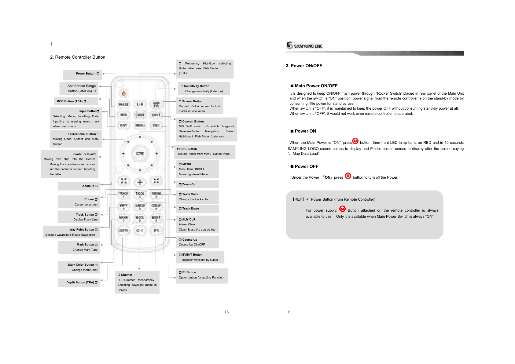
2. Remote Controller Button.................................................................................................................15
3. Power ON/OFF ................................................................................................................................16
4. Menu Composition ...........................................................................................................................17
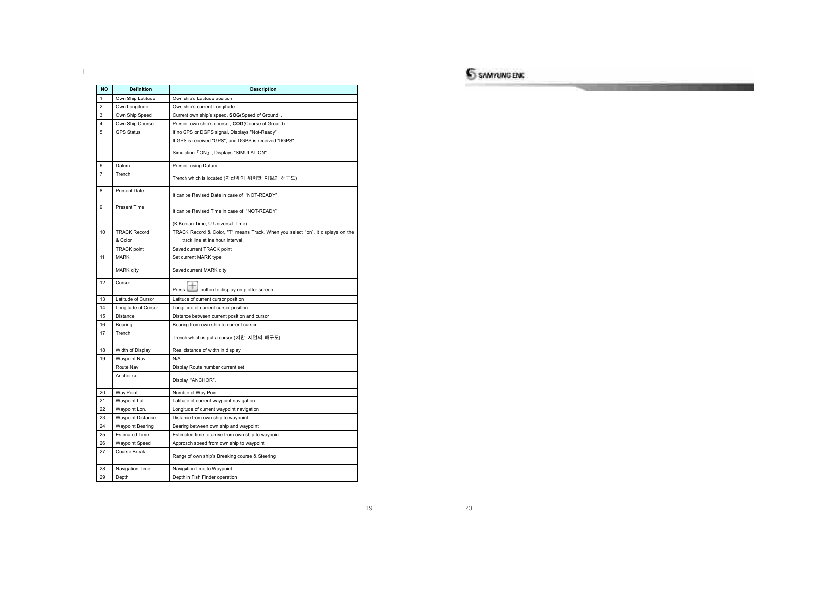
5. Plotter Display..................................................................................................................................18
4. Operating Instruction...............................................................................................................................23
1. Data.................................................................................................................................................24
1.1 Track Data ..............................................................................................................................24
1.2 Mark Data ...............................................................................................................................32
1.3 User Coast Line ......................................................................................................................40
1.4 Waypoint Data.........................................................................................................................46
1.5 Route Data..............................................................................................................................53
1.6 Disc Format ............................................................................................................................55
1.7 The Seabed Symbols ..............................................................................................................56
1.8 Software Update .....................................................................................................................57
2. Set Up .............................................................................................................................................58
2.1 Navigation Set Up ...................................................................................................................58
2.2. Alarm functions ......................................................................................................................69
2.3 How to set up Vessel...............................................................................................................75
2.4 Cursor Setup...........................................................................................................................79
2.5 Ship Tracking ..........................................................................................................................82
2.6 Simulation...............................................................................................................................85
2.7 Miscellaneous Set ...................................................................................................................86
3. System.............................................................................................................................................91
3.1 Satellite Information ................................................................................................................91
3.2 Print-Out (USB - TBA) .............................................................................................................94
3.3 Keyboard Test .........................................................................................................................96
3.4 System Set .............................................................................................................................97
3.5 System Information ...............................................................................................................106
5. System Maintenance & Diagnosis .........................................................................................................107

]
3
1. GPS PLOTTER
This chapter provides the overview of GPS Plotter to get you started using GPS Plotter with Fish
Finder.
1
GPS PLOTTER
4
1. GPS Overview
Global Positioning System IS based on the radio navigational system and satellites which provide an
unlimited number of users with accurate three dimensional positions, velocity and time in straight 24 hours,
worldwide coverage, under any weather condition.
GPS has two types of Positioning such as 3D and 2D.
3D Positioning is used to using in Airplane, which is required three positioning -Latitude, Longitude, Height.
In this positioning, Its required 4 satellites to make the position.
2D Positioning is to using Vessel/Ship, which is used only Latitude, Longitude without height.
In case of 2D positioning, Its required only 3 satellites to receive signal, then time zone for positioning will
be extended.
GPS gives more accurate positioning result always due to receiving signal from satellites, which are
revolving around the earth.
The GPS Plotter has received information from satellites and display own ship position, bearing, time, and
speed out of LCD screen.
Further it provides information for navigation on sail, more clear data together with port map and
Latitude/Longitude, Track, Event Mark based on High-resolution LCD implemented.

]
5
2. FEATURES
This chapter provides Features of NAVIS GPS Plotter.
GPS Antenna & Receiver
DGPS Antenna & Receiver, Beacon Receiver
Main Unit Features & Functions
Standard Components
2
FEATURES
6
1. GPS Antenna & Receiver
GPS Antenna
Type : All-weather Micro strip patch antenna
Power Supply : Receiver Module
Size & Weight : 102 x 65mm (+150mm mounting bar) 0.2kg

]
7
2. Main Unit Features & Functions
Positioning
Tracking Speed : Velocity; 1000Knots (514 m/s)
Acceleration; 4g
Signal Correction & Tracking : Full Auto(Tracking Micro Computer)
Accuracy: 15m RMS, PDOP≤3.0 (without SA) - NAVIS 3100(GPS)
Speed Accuracy : 0.1 Knots RMS, PDOP≤3.0 (without SA)
Data Recovery Time : 1 sec
Initial Positioning Time : 40 sec
Renewal interval of position data : 1sec
Operating Condition
Temperature : Antenna = -30C ~ +85C
Main Unit = -15C ~ +55C
Humidity : 95% (+30C ~ +60C)
Main specification
RGB Signal Output: All monitors compatible with RGB input are available, such
as CRT and Flat type Monitor
Resolution : 640 x 480 pixels
Power : 8V to +32V DC Approx. 5W
Weight & Dimension : 217x143x36, 760g
8
Navigation(1)
Drawing Method : Mercators
Scale Range : 1/2,500 ~ 1/37,500,000(about 0.2nm ~ 5,000nm)
Effective Display Range : Less than Laititude 85°
Menu : Pull-down Menu
Coast Line Chart : Display on the Tracking Screen
Track Display : Memory Interval –TRACK memory stop,
One sec. ~ 60 min. available.
0.01nm ~ 9.99nm variable selection
Memory Capacity - TRACK 20,000points
Users Line Drawing 7992points
Track Mark –100 points
Track Color –16 colors
Waypoint Memory and Route Memory point:
Waypoint Memory Point - 1,000 Points
Route Memory Point - 20 Routes (20 Points /1 Route)

]
9
Navigation(2)
Auxiliary Memory Unit: Coast Line, TRACK, Event, Waypoint,
Users Line to be saved.
Disk save and SD card available.
Data display : Target, Cursor(Distance, Latitude, Longitude), Time,
Course/Speed,
Distance, Interim Waypoint, Bearing/Distance, time,
Warning Line,
Course Break Steering, Depth line of Sea, Fill Land,
Ocean Deep, Sinking Ship/Undersea grasses,
Ownship, Zoom in/out
Alarm : Arrival Alarm, Course Break, Anchor Alarm, Boundary
Geodetic Datum: Selectable Datum in worldwide
Navigation data input/output format: In/Output device available
SAMYUNG, FURUNO, JRC, NMEA0183 (IEC 61162)
10
3. Standard Components
SGP-330 Plotter
No.
Item
Specification
Q’ty
Remark
1
GPS Plotter
SGP-330
1ea
2
GPS Antenna
SAN-60
1ea
3
Antenna Cable
RG-58C/U
10/20m
4
DC Cable
CVV SB 0.75 SQ MMx2C
3m
5
Spare Fuse
20mm, 250V 2A
2ea
6
Install. Material
Piece and Earth Cable etc.
1 Lot
7
Instruction Manual
English Manual
1 Lot
8
Remote Controller
REM-330
1ea
9
“Cable
2m wire cable
1ea
10
Remote Controller Bracket
Magnetic type Bracket
1ea
11
External Receiver
REM-331
1ea
Option
12
Rectifier (10A)
100/110/115/220/230V AC
Option

]
11
공란
12
3. Device & Display
This Chapter explains Device and Display about SGP-330.
Main Unit
Remote Controller Button
Power ON/OFF
Plotter Display
3
Device & Display

]
13
1. Main Unit
Front Panel
External Receiver Terminal
(option) connects to the external
Receiver. And install it where
you want
Built-in Receiver LED(Power Display LED) : Window built-in as a
standard and receiving signal from wireless remote controller .
Red LED lit on when Power ON and Remote Controller Power ON.
SD card, USB device (which will be available later on) inserting slot and terminal
SD-CARD: Coastline, track, event, waypoint and user coastline can be stored and Program can be updated
through this SD-Card.
USB HOST (available later on): It is a USB HOST terminal that can be connected with BACK-UP, external printer
and other devices (Available later on)
14
Rear Panel
RGB Output:
All monitors supportive with RGB
input, such as CRT, flat monitor,
LCD are available
Connecting to wire
remote controller:
DATA in/out:
Interface with other
products which
in/output of NMEA
DATA available
POWER INPUT:
Power input from Power
supply or Battery.
DC +8V ~ 36V available
GPS –ANT:
Receiving GPS
Active ANT signal
Power Switch:
Main switch for power-
On/Off.
FUSE Holder
20mm 2A FUSE
Earth Terminal

]
15
Frequency High/Low selecting
Button when used Fish Finder.
(TBA)
Sensitivity Button
Change sensitivity (Later on)
Screen Button
Convert Plotter screen to Fish
Finder or vice versa
Convert Button
N/S, W/E switch .+/- switch .Waypoint,
Reverse-Route Navigation. Select
High/Low in Fish Finder (Later on)
Input button
Selecting Menu, Inputting Data.
Inputting or erasing event mark
when used cursor
8 Directional Button
Moving Chart, Cursor and Menu
Cursor
Center Button
Moving own ship into the Center.
Moving the coordinator with cursor
into the center of screen. Inputting
the letter.
ESC Button
-Return Plotter from Menu -Cancel input
Track Button
Display Track Line
Course Up
Course Up ON/OFF
Zoom-In
Zoom-Out
Track Color
Change the track color.
Way Point Button
Execute waypoint & Route Navigation
ALM/CLR
Alarm: Clear
Clear: Erase the course line
EVENT Button
Register waypoint by cursor
MENU
Menu Item ON/OFF
Move high-level Menu
Cursor
Cursor on screen
Power Button
Track Erase
Mark Button
Change Mark Type
Mark Color Button
Change mark Color
Depth Button (TBA)
F1 Button
Option button for adding Function
Dimmer
LCD Dimmer, Transparency
Selecting day/night mode in
Screen
2. Remote Controller Button
Sea Bottom Range
Button (later on)
수심범위를 변경시
사용
MOB Button (TBA)
16
3. Power ON/OFF
Main Power ON/OFF
It is designed to keep ON/OFF main power through “Rocker Switch”placed in rear panel of the Main Unit
and when the switch is “ON”position, power signal from the remote controller is on the stand-by mode by
consuming little power for stand by use.
When switch is “OFF”, it is maintained to keep the power OFF without consuming stand-by power at all.
When switch is “OFF”, it would not work even remote controller is operated.
Power ON
When the Main Power is “ON”, press button, then front LED lamp turns on RED and in 10 seconds
SAMYUNG LOGO screen comes to display and Plotter screen comes to display after the screen saying
“…Map Data Load”
Power OFF
Under the Power ONpress button to turn off the Power.
REF☞ Power Button (from Remote Controller)
For power supply, Button attached on the remote controller is always
available to use. Only it is available when Main Power Switch is always “ON”.

]
17
4. Menu Composition
1.Data
1. Track Date
2, Mark Data
3. User’s Line
4. Waypoint Data
5, Route Data
6. Disk Format
7. Seabed Type
2.Set
1. Navigation Set
2. ALARM SET
3. Own Ship Set
4. Cursor Set
5. Ship Tracking
6. Simulation
7. ETC set
3.System
1. Satellite INFO
2. Screen Print
3. Keyboard Test
4. System Set
5. System Info
8. Program update
18
5. Plotter Display
GPS Plotter Display
9
2
1
24
5
6
7
11
21
22
25
26
27
28
18
29
12
3
4
8
10
23
13
14
15
16
17
19
20

]
19
NO
Definition
Description
1
Own Ship Latitude
Own ship’s Latitude position
2
Own Longitude
Own ship’s current Longitude
3
Own Ship Speed
Current own ship’s speed, SOG(Speed of Ground) .
4
Own Ship Course
Present own ship’s course , COG(Course of Ground) .
5
GPS Status
If no GPS or DGPS signal, Displays "Not-Ready"
If GPS is received "GPS", and DGPS is received "DGPS"
SimulationON, Displays "SIMULATION"
6
Datum
Present using Datum
7
Trench
Trench which is located (자선박이 위치한 지점의 해구도)
8
Present Date
It can be Revised Date in case of NOT-READY
9
Present Time
It can be Revised Time in case of NOT-READY
(K:Korean Time, U:Universal Time)
10
TRACK Record
& Color
TRACK Record & Color, "T" means Track. When you select “on”, it displays on the
track line at ine hour interval.
TRACK point
Saved current TRACK point
11
MARK
Set current MARK type
MARK qty
Saved current MARK qty
12
Cursor
Press button to display on plotter screen.
13
Latitude of Cursor
Latitude of current cursor position
14
Longitude of Cursor
Longitude of current cursor position
15
Distance
Distance between current position and cursor
16
Bearing
Bearing from own ship to current cursor
17
Trench
Trench which is put a cursor (치한 지점의 해구도)
18
Width of Display
Real distance of width in display
19
Waypoint Nav
N/A.
Route Nav
Display Route number current set
Anchor set
Display ANCHOR.
20
Way Point
Number of Way Point
21
Waypoint Lat.
Latitude of current waypoint navigation
22
Waypoint Lon.
Longitude of current waypoint navigation
23
Waypoint Distance
Distance from own ship to waypoint
24
Waypoint Bearing
Bearing between own ship and waypoint
25
Estimated Time
Estimated time to arrive from own ship to waypoint
26
Waypoint Speed
Approach speed from own ship to waypoint
27
Course Break
Range of own ships Breaking course & Steering
28
Navigation Time
Navigation time to Waypoint
29
Depth
Depth in Fish Finder operation
20

]
21
22
Day/Night Mode in Plotter Display
Press ( ) Open the menu such as Transparency, Day/Night mode

]
23
4. Operating Instruction
This chapter provides Operating Instruction in NAVIS series.
DATA
SET
SYSTEM
4
Operating Instruction
24
1. Data
1.1 Track Data
1.1.1 Track Set
It is a function to set own ships Track in navigation.
Total track to be saved is 20,000 points, When it comes to be full memory, delete point one by one
[REF] When selected ON, current track line is saved , while selected OFF, track line is not drawn
and can not be saved.
Track Saving unit Set
[1.Data] [1.Track Data] [1.Setup] [2.Selection]
(Whenever pressed, [Time/Distance] repeatedly selected.)
Track Data Save ON/OFF
[1.Data] [1.Track Data] [1.Set] [1.Save]
(ON/OFF) changeably selected whenever pressed)

]
25
< TRACK Memory Interval & Max. Memory time, Date>
Memory Interval
Maximum Memory time & Date
5 sec
27h 47m = 1day 4h
10 sec
55h 33m = 2days 7h
30 sec
166h 39m = 6days 22h
1 min
333h 19m = 13days 21h
5 min
1666h 35m = 69days 10h
10 min
3333h 10m = 138days 21h
30 min
9999h 30m = 416days 15h
60 min
19999h = 833days 7h
REFin Remote Controller
Track Memory Interval Set Up
Time setup
[1.Data] [1.Track Data] [1.Set] [3.Time]
•Distance setup
[1.Data] [1.Track Data] [1.Set] [4.Distance]
Track Color Selection
[1.Data] [1.Track Data] [1.Set] [5.Color]
After selecting the wanted color, press,
Track Line Thick selection
[1.Data] [1.Track Data] [1.Set] [6.Shape]
(Whenever pressed, [thin/thick] repeatedly selected)
Time interval "T" Mark display
[1.Data] [1.Track Date] [1.Set] [7.T-Mark]
(Whenever pressed, [ON/OFF] repeatedly selected)
26
1.1.2 Track Clear
Use this function to erase the TRACK line of the vessel.
Track Clear
[1.Data] [1.Track Data] [2.Clear] [1.All Clear]
After selecting "Yes" , (Whenever pressed, thin/thick) repeatedly selected)
Track clear by Color
[1.Data] [1.Track Data] [2.Clear] [2.Color Clear]
After selecting the color, press

]
27
1.1.3 Track CALC
Use this function to calculate the Vessel’s TRACK.
All track CALC.
[1.Data] [1.Track Data] [3.CALC] [1.All CALC]
Selected color Track CALC
[1.Data] [1.Track Data] [3.CALC] [2.Color CALC]
After selecting the selected color, press
28
1.1.4. Track Save
Use this function to save TRACK DATA to selected device while vessel navigates.
Save Track in built-in ROM
[1.Data] [1.Track Data] [4.Save] After input file name
(0001 ~9999), press [built-in ROM] and press
Save track into SD card
[1.Data] [1.Track Data] [4.Save] After input file name
(0001 ~9999), press [SD] and press

]
29
Saving Track by Transmitting Data
- It is the function to save after transmitting to other product through external in/output terminal
[1.Data] [1.Track Data] [4.SDave] After input File
name (0001 ~ 9999), press [COM. PORT] and press
30
1.1.5 Track Load
Use this function to load saved file from “1.1.4 Track Save”and Display on the plotter screen.
Built-in ROM Track Load
[1.Data] [1.Track Data] [5.Load [Built-in ROM]
After selecting Geodetic Conversion, press .
SD Card Track Load
[1.Data] [1.Track Data] [5.Load] [SD Card]
After selecting the file to be loaded, press .
Once you load the saved TRACK file, any previous TRACK drawn on the screen will be
erased.
Caution

]
31
1.1.6 Track Erase
Use this function to erase the TRACK file from storage device at '1.1.4 Track Save'.
Take care when using the erase menu. Files erased during this process cannot be recovered.
ERASE Built-in ROM
[1.Data] [1.Track Date] [6.Erase] [Built-in ROM]
After selecting YES, press
ERASE USER CARD
[1.Data] [1.Track Data] [6.Erase] [SD CARD]
After selecting the file to be erased, press after selecting "YES", Press
32
1.2 Mark Data
1.2.1 Mark Select
Use this function to select which MARK type to show on the screen. There are 21 unique MARK types.
[REF] 1. Shortcut key and button.
2. After selecting (Line Start) ◈or (Line Continue) mark, move cursor on plotter screen and
press, to draw Line. If you want to erase the line, make the cursor overlap each MARK and press
.
MARK type and MARK color select
[1.Data] [2.Mark Data] [1.Select] After selecting Mark
Type, press after selecting Mark Color, press

]
33
34
1.2.2 MARK Append
Use this function to append MARK at location of vessel or certain Latitude/Longitude.
[REF]Shortcut to input MARK position
1. Without cursor, press button to input MARK at vessel position.
2. Press , Move cursor, Press to input easier..
MARK can be input up to 10,000 points, if you need to input more than 10,000 points, it displays “all
mark points used”.
Mark Append at own ship’s position
[1.Data] [2.Mark Data] [2.Append] [1.Own ship’s position]
Mark append to a certain Longitude/Latitude
[1.Data] [2.Mark Data] [2.Append] [2.Lat/Long]
After inputting Longitude value, press after inputting latitude value, press

]
35
1.2.3 Mark Clear
'1.2.2 Function to clear a mark
Clears all mark
[1.Data] [2.Mark data] [3.clear] [1.all clear]
after selecting YES, press .
Clear own ship’s mark
[1.Data] [2.mark Data] [3.Clear] [2.Ownship position]
.
Clears mark in color
[1.Data] [2.Mark data] [3.clear] [3.color clear]
after selecting the color, press .
36
[REF] Shortcut to clear the Mark
On the plotter screen, place on the mark to clear by using direction keyand press
Clear MARK in Lat/Long
[1.Data] [2.Mark Data] [3.Clear] [4.Lat/Lon]
After selecting Lat., press after selecting Lon., press .

]
37
1.2.4 MARK SAVE
'1.2.2 MARK is saved to saving device as a file.
SAVE in built-in ROM
[1.Data] [2.Mark Data] [4.save] after inputting file name
(0001 ~ 9999), press [built-in ROM] and press
SAVE in SD CARD
[1.Data] [2.Mark Data] [4.save] after inputting file name
(0001 ~ 9999), press [SD CARD] and press
MARK SAVE by sending data
- It is possible to send to another SYSTEM through external in/output terminal and to save.
[1.Data] [2.Mark Data] [4.save] after inputting file
name (0001 ~ 9999), press [COM port] and press
38
1.2.5 MARK Load
'1.2.4 Display a mark on the plotter screen after recalling a saved file from a storage device.
LOAD MARK STORED in built-in ROM
[1.Data] [2.Mark data] [5.Load] [Built-in ROM]
after select changing Geodetic , press
LOAD MARK stored in SD CARD
[1.Data] [2.Mark data] [5.Load] [SD CARD]
After select the file to be loaded, press
Be advised that any MARK currently displayed on the plotter screen is deleted when the
saved MARK file is recalled.
Caution

]
39
1.2.6 MARK ERASE
'1.2.4 Erasing a saved MARK file from a storage device.
Take care when using the erase menu, files erased during this process cannot be recovered.
Built-in ROM Erase
[1.Data] [2.Mark data] [6.Erase] [Built-in ROM]
after select YES, press
SD CARD ERASE
[1.Data] [2.Mark data] [6.Erase] [SD CARD]
after select the file, press after select “YES", press
40
1.3 User Coast Line
1.3.1 Coast Line Mark
This function is used to display a coastal line drawn by a user onto the plotter screen. In the ONsetting,
the coastal line drawing is displayed.
COASTAL LINE ON/OFF
[1.data] [3.User’s Line] [1.Display] SelectON/OFF,
Press
Table of contents
Other Samyung ENC Marine Equipment manuals
Popular Marine Equipment manuals by other brands

Furuno
Furuno Network Sounder DFF3 Operator's manual

Raymarine
Raymarine ST60 Tridata Owner's handbook

Carillon Lumineux
Carillon Lumineux Melodys Flash Instruction and operation manual

Remoran
Remoran WAVE 3 installation instructions

Teledyne
Teledyne WORKHORSE II Operation manual

KVH Industries
KVH Industries TracNet H90 installation guide