Oilon OilonCooling Ck5 User manual

M8015 2337EN
11 September 2023
Installation and operation manual
OilonCooling Ck
Read these instructions carefully before installation, use, or maintenance


Contents
1 Introduction
1.1 Safety notice and warnings........................................................................ 3
1.2 Delivery contents.........................................................................................4
2 Installation
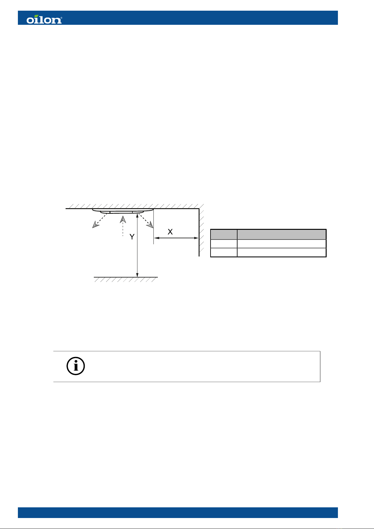
2.1 Installing cooling unit.................................................................................. 6
2.2 Pipe installation...........................................................................................7
2.3 Electrical installation....................................................................................8
3 Operation
3.1 Remote control..........................................................................................10
3.2 General functions......................................................................................11
3.3 Setting the time.........................................................................................11
3.4 Resetting the cooling unit......................................................................... 11
3.5 Adjusting room temperature..................................................................... 12
3.6 Operating modes.......................................................................................12
3.7 Selecting fan speed.................................................................................. 12
3.8 Setting a timer...........................................................................................12
3.9 Turbo function........................................................................................... 13
3.10 Econo function.......................................................................................... 13
3.11 Quiet function............................................................................................14
3.12 Sleep function........................................................................................... 14
4 Maintenance
4.1 Tasks at the start and end of the heating season.................................... 15
4.2 Cleaning the air filter................................................................................ 15
4.3 Cleaning the cooling unit.......................................................................... 16
4.4 Troubleshooting.........................................................................................16
5 Technical data
5.1 Technical data........................................................................................... 17
5.2 Dimensions................................................................................................17
5.3 Wiring diagram..........................................................................................18
5.4 Terms of sale and warranty......................................................................19
M8015 2337EN 1 (20)

2 (20) M8015 2337EN

1 Introduction
1.1 Safety notice and warnings
Read these instructions carefully before installation, commissioning, operation, or
maintenance of the device. The given instructions must be followed. Throughout this
manual, the following symbols are used to point out very important information:
Use special caution. The DANGER symbol indicates an immediate
hazard that will result in serious injury or death.
Use special caution. The WARNING symbol indicates a hazard that
may result in serious injury or death.
Use caution. The CAUTION symbol indicates a hazard that may result
in an injury.
Pay attention. The NOTICE symbol indicates a risk of damage to the
equipment, components, or surroundings.
The ‘i’ (info) symbol indicates important information as well as useful
tips and hints.
Keep these instructions as well as the electrical diagrams available near the device.
Installation or commissioning of the appliance is to be carried out by
authorized and trained personnel only, adhering to all local regulations
and requirements.
Wear proper personal protective equipment, such as protective
footwear, gloves, and safety goggles when necessary.
Before any maintenance or servicing, switch off electricity using the
main switch.
M8015 2337EN 3 (20)

Use only fuses with the correct rating.
Do not push items into the air inlet or outlet when the cooling unit is in
operation, as this may result in an injury or damage to the equipment.
Do not direct the air flow directly towards people.
To avoid slipping, keep floor surfaces dry, and seal off or report any
leaks that you detect.
Do not place a heater or other heat source near the unit.
Do not obstruct the air inlet or outlet. Obstructions will lower the unit’s
performance and may cause a malfunction.
If the unit will be out of use for an extended period of time, disconnect
power from the cooling unit’s main switch.
1.2 Delivery contents
Check the contents of the delivery immediately. If some of the
accessories specified in the order are not included in the delivery, notify
the equipment dealer within five days.
The cooling unit is delivered with an installation kit for connecting one cooling unit into
a heat pump’s brine circuit. If you install several cooling units in the same location,
determine the necessary connection components on a case-by-case basis.
Kit contents
● circulation pump
● Pump connector with shut-off valves, 1½" x ¾"
● Miniature ball valve, F ¾"
● Check valve, 1¼"
● Two-way valve and electric actuator
● Relay and circuit breaker for circulation pump control
4 (20) M8015 2337EN

Removing the packaging
Remove the cardboard packaging from around the product. Check the unit for
transportation damage. If there is damage, report the damage immediately to the
carrier who delivered the unit.
M8015 2337EN 5 (20)

2 Installation
2.1 Installing cooling unit
Place the cooling unit as high as possible. Cold air flows downwards.
If you bring the pipes to the unit through a wall behind the unit, create a passthrough
for the pipes. The dimensions required for locating the pass through are indicated on
the cooling unit mounting plate.
Installation site requirements
● There are no obstructions 1000 mm in front of or next to the air outlet.
Pos. Distance
X >1000 mm
Y >1000 mm
● There are no heat sources or devices that generate water vapor near the unit.
● The location is optimal for air circulation within the room.
● A condensate drain can be installed conveniently.
● The unit is not next to a doorway.
● The installation height is correct.
Making a mounting box for the cooling unit
A service hatch will be mounted inside the mounting box, at the edge of
the box.
The cooling unit requires a mounting box for installation. This box must be insulated,
as it extends into the cool intermediate floor structure. Make the mounting box from
laminated timber or similar material.
● When making the box, leave room for a service hatch (width: around 200 mm) next
to the cooling unit for making connections and bleeding pipes.
Minimum mounting box width and length:
● Ck5: 850 mm
● Ck9: 1150 mm
6 (20) M8015 2337EN

Installing mounting hardware inside the mounting box
When using screws instead of threaded bars to fasten the unit, install
mounting supports inside the box.
The cooling unit can be fastened to the mounting box either with threaded bars or
screws.
When using threaded bars to fasten the cooling unit, fasten installation supports to the
roof of the box.
● Select a secure mounting method based on the mounting box material.
● Mark the mounting locations for the cooling unit using the cardboard template
included in the delivery.
● Do not tighten the nuts after installing the threaded bars.
● Install washers as shown in the image.
Cooling unit installation
1. Fasten the mounting box between ceiling structures.
2. Carefully lift the cooling unit into place and mount corner brackets onto the threaded
bars.
3. Adjust the height using the washers and nuts. Consider the final height of the ceiling
lining.
4. Tighten the fastening nuts.
5. Fasten the grille in place with the supplied fastening screws.
Alternatively, fasten the unit with screws to the mounting supports inside the box.
2.2 Pipe installation
Make the pipe connections as shown in the piping diagram. Check the connections. To
prevent condensation, carefully insulate the pipes and pass throughs.
Pipe connections, Ck5
Pos. Item
1 Bleed valve
2 Brine out, 3/4"
3 Brine in, 3/4"
4 Condensate drain
M8015 2337EN 7 (20)

Pipe connections, Ck9
Pos. Item
1 Bleed valve
2 Brine out, 3/4"
3 Brine in, 3/4"
4 Condensate drain
Condensate tray installation
The condensate tray ensures that any condensate from pipe joints is led back into the
unit, preventing moisture damage to any surrounding structures.
1. Remove plastic plugs.
2. Install the condensate tray as shown in the image.
A: insulation
3. Insulate the condensate tray.
Condensate drain installation
● To prevent air pockets, cut the condensate drain as short as possible and use a
downward slope (min: 2%).
● Minimum water seal depth: 50 mm.
● The highest point in the condensate drain must not be higher than 200 mm from the
top of the cooling unit.
● Carefully insulate the condensate drain pipe.
● If there are several cooling units in the room, you can chain the condensate drain
pipes as shown in the image.
2.3 Electrical installation
To access the control unit, remove the grille and the metal cover plate as shown in the
image. Make the electrical connections according to the electrical diagrams.
8 (20) M8015 2337EN

Two-pipe system
Power supply for valve actuator
Protective earth
M8015 2337EN 9 (20)

3 Operation
3.1 Remote control
Press only one button at a time. Pressing two or more buttons simultaneously may
cause a malfunction.
The cooling unit will beep when it has received a signal from the remote control. If the
signal does not reach the unit for some reason, there will be no beep.
Layout
Pos. Function
1 Screen
2 Fan speed
3 Mode setting
4 Econo function
5 Sleep function
6 Turbo function
7 Brightness
adjustment and
keylock
8 Clock setting
Pos. Function
9 Room temperature
setting
10 Power On/Off
11 Timer Off and Off
12 Quiet function
13 Air flow vane
14 Air flow direction
15 Reset button
Batteries
The batteries (2 pcs, AAA) are under a sliding lid at the lower section of the remote
control. To fully remove the sliding lid, lift slightly from the top middle part of the lid and
slide downwards. Place the batteries the right way around. Reinstall the sliding lid.
● The batteries will last for around 1 year.
● Do not use rechargeable batteries.
● If the unit will be out of use for an extended period of time, remove the batteries.
10 (20) M8015 2337EN

3.2 General functions
Power On/Off
To turn the unit on or off, press the Power On/Off button. When switched on, the unit
will operate with the settings shown on the remote control’s screen.
Screen brightness adjustment
To change the screen brightness, press the DIM button.
Keylock
To lock the remote control keys, press and hold the DIM button (with the key icon next
to it) for two seconds. A key icon will appear on the screen.
● Unlock the keys by pressing and holding the key button for two seconds.
Air flow direction
When the SWING button is pressed, the unit will automatically adjust the air flow
direction. Disable the function by pressing the button again.
Vane adjustment
Press the VANE button to browse between different vane positions.
3.3 Setting the time
1. Remove the sliding lid. Lift slightly from the top middle part of the lid, and slide
downwards.
2. Press the small Clock button with the tip of a pencil or similar tool.
● The clock icon and the time will start flashing on the remote control screen.
3. Set the time with the up and down arrow.
● To browse through numbers faster, keep the arrow button pressed.
4. Press the CLOCK button. The clock icon and the time will stop blinking.
5. Slide the lid back in place.
3.4 Resetting the cooling unit
If there is a malfunction, return the unit to normal mode by resetting the cooling unit.
Remove the sliding lid. Lift slightly from the top middle part of the lid, and slide
downwards. Press the small Reset button with the tip of a pencil or similar tool.
The system will restart in approximately 2 minutes.
M8015 2337EN 11 (20)

3.5 Adjusting room temperature
Set the room temperature with the arrow buttons. Available temperature range: 18–30
°C.
The set room temperature will be shown on the remote control screen.
3.6 Operating modes
To scroll between different operating modes, press the Mode button repeatedly.
Mode Description
COOL The unit operates at the set temperature.
FAN The unit circulates air without cooling. In FAN mode, the Sleep, Econo, and Turbo as
well as the arrow buttons are disabled.
DRY The equipment removes moisture from the air.
HEAT If the unit is connected to a heating system, the unit will operate at the set temperature.
AUTO The unit will operate in COOL or HEAT mode depending on the set temperature and the
current room temperature.
3.7 Selecting fan speed
Scroll between fan speed modes by pressing the fan button repeatedly. Available
modes:
● AUTO (automatic)
● LO (slow)
● MED (medium)
● HI (high)
In AUTO mode, the unit functions automatically. The system detemines the fan speed
by deducting the room temperature setting from the actual room temperature, see the
table.
Difference Fan speed
3 °C or more HI (high)
2 °C MED (medium)
1°C or less LO (slow)
3.8 Setting a timer
Use the timer functions to switch the unit on or off at a specific time. The timer operates
only once and must be set again the next day.
12 (20) M8015 2337EN

Setting the timer to switch the unit on
1. Press the timer On button. The time and the text ‘ON’ will start flashing.
2. Set the start time with the arrow buttons.
● Pressing an arrow button will move the time 10 minutes forwards or backwards.
To browse through numbers faster, keep the arrow button pressed.
3. Press the timer On button. The time will stop blinking.
Setting the timer to switch the unit off
1. Press the timer Off button. The time and the text ‘Off’ will start flashing.
2. Set the stop time with the arrow buttons.
● Pressing an arrow button will move the time 10 minutes forwards or backwards.
To browse through numbers faster, keep the arrow button pressed.
3. Press the timer Off button. The time will stop blinking.
3.9 Turbo function
The Turbo function will speed up the current function by opening the brine circuit valve
(if present) and setting the fan at maximum speed for half an hour. The function is
available in COOL mode, HEAT mode (if the unit is connected to heating), and AUTO
mode.
Activate (and deactivate) the function by pressing the Turbo button.
● When the TURBO function is on, the text TURBO is shown on the remote control
screen.
● The set temperature and fan speed will not be displayed.
The Turbo function will be automatically deactivated when:
● Temperature reaches 18 °C (in COOL mode)
● Temperature reaches 30 °C (in HEAT mode)
● You switch modes by pressing the Mode button
● You switch the unit off with the On/Off button
3.10 Econo function
Use the Econo function to temporarily run the unit at reduced capacity. The function is
available in COOL mode, HEAT mode (if the unit is connected to heating), and AUTO
mode.
Activate (and deactivate) the function by pressing the Econo button.
● When the ECONO function is on, the text ECONO is shown on the remote control
screen.
● The set temperature and fan speed will not be displayed.
The Econo function will be automatically deactivated when:
● Temperature reaches 25 °C (in COOL mode)
● Temperature reaches 25 °C (in HEAT mode)
● You switch modes by pressing the Mode button
M8015 2337EN 13 (20)

3.11 Quiet function
When using the Quiet function, the fan will run in power saving mode (at minimum
speed).
Activate or deactivate the Quiet function by pressing the Quiet button.
● The function is available in COOLING, HEATING, and AUTO mode.
● The text QUIET will be shown on the screen. Fan speed will not be displayed.
● In COOLING mode, the room temperature shown on the screen will automatically
increase by 1 °C in one minute.
3.12 Sleep function
The Sleep function automatically adjusts the room temperature setting one hour after
the function has been activated.
Activate or deactivate the SLEEP function by pressing the Sleep button.
● In COOL mode, the unit will automatically increase the set temperature by one
degree after one hour.
● In HEAT mode, the unit will automatically decrease the set temperature by one
degree after one hour.
● If the unit is switched off or it shuts down due to a power outage, the SLEEP
function will be deactivated.
14 (20) M8015 2337EN

4 Maintenance
4.1 Tasks at the start and end of the heating season
At the start of the cooling season
● Install new batteries in the remote control.
● Check that the cooling unit is installed correctly.
● Check that the cooling unit’s air flow is free of obstructions.
● Check that there are no bends, dents, or blockages in the condensate drain pipe.
● Do not start the cooling unit without air filters. Unfiltered air may cause issues in the
unit’s operation.
At the end of the cooling season
● Turn off power from the main switch.
● Clean the cooling unit and the air filters.
● To remove moisture from inside the unit, run the fan with the FAN function for 2–3
hours.
● Remove the batteries from the remote control.
Outside the cooling season, it is recommended to run the equipment for a short time
every 2 months. This will lengthen the life of the circulation pump.
4.2 Cleaning the air filter
Clean the air filter regularly. If the air filter is dirty, air flow will be weaker, which will
increase power consumption. In extremely dusty environments, clean the air filter once
every two weeks or as often as necessary. The blue air filter prevents bacteria and
mold from growing in the dirt captured by the air filter.
1. Detach the grille by turning the fastening screws (2 pcs) one quarter of a turn.
2. Open the grille and detach the filter from the grille.
3. Vacuum the air filter.
4. If necessary, wash the filter with mild detergent. Dry carefully before reinstalling.
5. Reinstall the filter, lift the grill back up to its normal position, and secure with the
fastening screws.
M8015 2337EN 15 (20)

4.3 Cleaning the cooling unit
Carefully clean the air outlet and fan. If the air outlet or fan are dirty, clean with a moist
towel. If necessary, use mild detergent. Dry with a dry cloth.
Do not use solvents or polishing compounds for cleaning.
4.4 Troubleshooting
Problem Cause/corrective action
The cooling unit does not start. Check the wires for damage.
Check that the circuit breaker has not tripped.
The unit works but doesn’t provide
enough cooling.
Check the room temperature setting.
Check if the air filter is dirty or clogged.
Check if apartment doors or windows are closed.
Check if air flow from the cooling unit is blocked.
Check if the unit’s brine circulation is blocked.
Check the brine circulation for air bubbles.
Check that the brine circuit pump is operating correctly.
There is steam coming out of the
unit when the unit is in operation.
Water vapor may form when hot indoor air and cold cooling air
become mixed.
The remote control does not work. Check the remote control’s batteries.
16 (20) M8015 2337EN

5 Technical data
5.1 Technical data
Ck5 Ck9
Cooling capacity, kW* 4.250 10.8
Max. input power, fan, W 75 110
Coefficient of performance** 34 68
Cooled floor area, m280–200 200–400
Weight, kg 22 40
Placement Ceiling Ceiling
*Cooling capacity in recommended installation conditions, brine inlet temperature: +7
°C, indoor temperature: +27 °C.
**The coefficient of performance calculation accounts for one circulation pump.
5.2 Dimensions
Main dimensions, mm Dimensions, portion
embedded in the ceiling
Model
Height Width Depth Height Width Depth
Ck5 65 720 720 280 574 574
Ck9 67 950 950 320 844 844
Dimensional drawings, Ck5
Dimensions, Ck5 ver. 1
CD: condensate drain connection
M8015 2337EN 17 (20)

Dimensional drawings, Ck9
Dimensions, Ck9 ver. 1
CD: condensate drain connection
5.3 Wiring diagram
Wiring diagram, two-pipe system
18 (20) M8015 2337EN
This manual suits for next models
1
Table of contents
Popular Fan manuals by other brands

dreo
dreo DR-HTF007S user manual

Bergstrom
Bergstrom K311 manual

Swegon
Swegon COLIBRI Ceiling CR Installation, commissioning maintenance

Honeywell
Honeywell HYF260B Series owner's manual

Hitachi
Hitachi RCIM-0.4FSRE Installation & operation manual

Fanimation
Fanimation FARGO FP3320 Series Set-up and maintenance instructions sheet

Craftmade
Craftmade Cameo CA60 Specifications

Craftsman
Craftsman 125.16812 Operator's manual

EUROM
EUROM 48 instruction manual

HAWK ENTERPRISES
HAWK ENTERPRISES BVP50 user manual

Harbor Breeze
Harbor Breeze BTH44ABZC5C installation guide

International comfort products
International comfort products FEM4X installation instructions