4Harmann Polska Sp. z o.o. Kokotów 703 | 32-002 Kokotów NIP 6793033048 | REGON 121200107
Bathroom fan
1. IMPORTANT INFORMATION
These instructions contain important information on installation, commissioning and maintenance.The information does not exempt from the necessity of own assessment and verication for use in a given application.
All rights reserved in the eld of notication of protection rights, disposal, copying and transfer. We assume no responsibility for the completeness or correctness of this documentation. Information status: 08/01/2021,v1.0.
The device is manufactured in accordance with the recognized rules of technical knowledge, nevertheless there is a risk of injury or material damage.
• Before installing and using the device, read this documentation completely and carefully.
• Keep this manual where it is easily accessible to all users.
• Always pass the device on to third parties together with the manual.
2. REGULATIONS
The devices should be installed, operated, maintained and serviced only by qualied and authorized personnel having the required authorizations, in accordance with the health and safety rules. Follow the guidelines
contained in this documentation, generally applicable standards, regulations, technical conditions as well as national and European law in the eld of accident prevention and environmental protection.
3. GENERAL SAFETY INSTRUCTIONS
Designers, installers and facility operators are responsible for the assembly, connection and operation in accordance with the regulations and purpose.
• The device should be checked for visible cracks, missing elements.
• It is not allowed to operate an incomplete or damaged device.
• The operating parameters of the device must not be exceeded during operation.
• In the event of failure or other abnormalities, turn o the device and make sure that unauthorized restarting will not be possible.
• Provide protection in accordance with the applicable electrical regulations, protection against contact and sucked up the foreign objects into the interior of the device and keeping the safety distances.
• Protective devices or installations must not be dispensed and their proper operation must not be disturbed.
• The device may not be used by persons (including children) with reduced physical, sensory or mental abilities, or by persons without appropriate experience and knowledge, unless supervision or instructions have
been given regarding the use of the device by a person responsible for their safety.
• Children should be kept away from the device.
3.1 PURPOSE
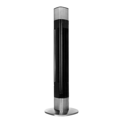
REY and NAX bathroom fans are designed to extract clean air in general ventilation systems in residential, oce, public buildings and in commercial and service facilities as well as educational facilities. Using it as intended,
it is necessary to read the instructions carefully, especially chapter no. 3. GENERAL SAFETY INSTRUCTIONS.
4. DIMENSIONS
Please seeTab.1 Dimensions and Pict.1 Dimensions on page 1.
5. INSTALLATION, CONNECTION AND COMMISSIONING
WARNING!Before starting work, disconnect the power supply (all poles) and make sure that unauthorized restarting will not be possible. Installation and electrical connections must be made
by authorized electricians, in accordance with the instructions and applicable regulations, PN and EN standards, health and safety regulations as well asTechnical Conditions. During work, use
certied protective gloves and insulated tools. The following conditions and instructions in chapter 3 must be respected.
5.1 INSTALLATION
• In the bathroom, the fan should be mounted at a height not lower than 2.3 m from the oor level or choose a dierent place for the installation of the fan, taking into account the safety zones in the bathroom
in relation to the IP class of the device, in accordance with the current regulations.
• The fan must not be installed in an explosion hazard zone or in a place where it is exposed to water splashes or high temperature.
• Take care that no condensate (water) ows to the device.
• It is not allowed to install the fan in a room with solid or liquid fuel replaces or with gas devices taking the air for combustion from the room and with gravity exhaust gas discharge.
• Never connect the fan to chimney and ue gas pipes!
• Only certied materials and assembly accessories should be used, which must be supplied on your own.
• Do not remove or change the information signs attached to the device.
5.1.1 ASSEMBLY
1. The fan should be mounted in the previously prepared hole at the end of the ventilation duct or the inlet to the chimney. The area around the opening must be at and stable. Make sure that there are no
installations at the assembly site.
2. Remove the front panel of the fan (Pict.3) and insert the device into the hole to mark the mounting points and the cable passage.Then, drill the mounting holes (Pict. 2).
3. Pass the power cable through the cable entry and, making sure that there are no foreign objects remain inside the duct, x the fan casing in a way that allows for later disassembly.
4. Install the front panel by gently latching the hooks.
5.2. ELECTRICAL CONNECTIONS
• Electrical connections must be made in accordance with the relevant diagrams.
• The supply voltage and frequency must comply with the specications on the nameplate!
• On the power supply line must be installed a main switch with a contact clearance of at least 3 mm, which disconnects all poles.
• The main switch must be easily accessible.
• The type, cross-section of the cables and the method of laying them must be selected by an authorized electrician.
5.3 COMMISSIONING
• Make sure that the device has been installed and connected in accordance with the instructions.
• Check all mechanical and electrical protective measures (e.g., covers, earthing, safety installations).
• During commissioning, check that there are no vibrations, abnormal noise, etc.
6. WIRING DIAGRAMS AND ADJUSTMENT INSTRUCTIONS
6.1 STANDARD FAN
Please see Pict.4Wiring diagram on page 2.
6.2T FAN WITH TIMER
Please see Pict.5 Access to electrical connection and Pict.6Timer system wiring diagram and time-adjusting diagram on page 2.
The supply voltage must be permanently connected to the L, N terminals (to ensure the device standby). Additionally, connect the same phase L with a third wire, through the switch to theT terminal. After setting the switch to„ON”,
the supply voltage will be applied to the control input„T”and fan will start work. After changing the position to„OFF”, the fan will run for the set delay time. The timer delay value can be set between 2 minutes and 30 minutes.
To increase the value of settings, turn potentiometers clockwise.To decrease the value of the settings, turn the potentiometer counterclockwise.
EN


