Copyright 2010.All Rights Reserved.
www.okinausa.com 7 REV012011-V03
PACKAGE CONTENTS
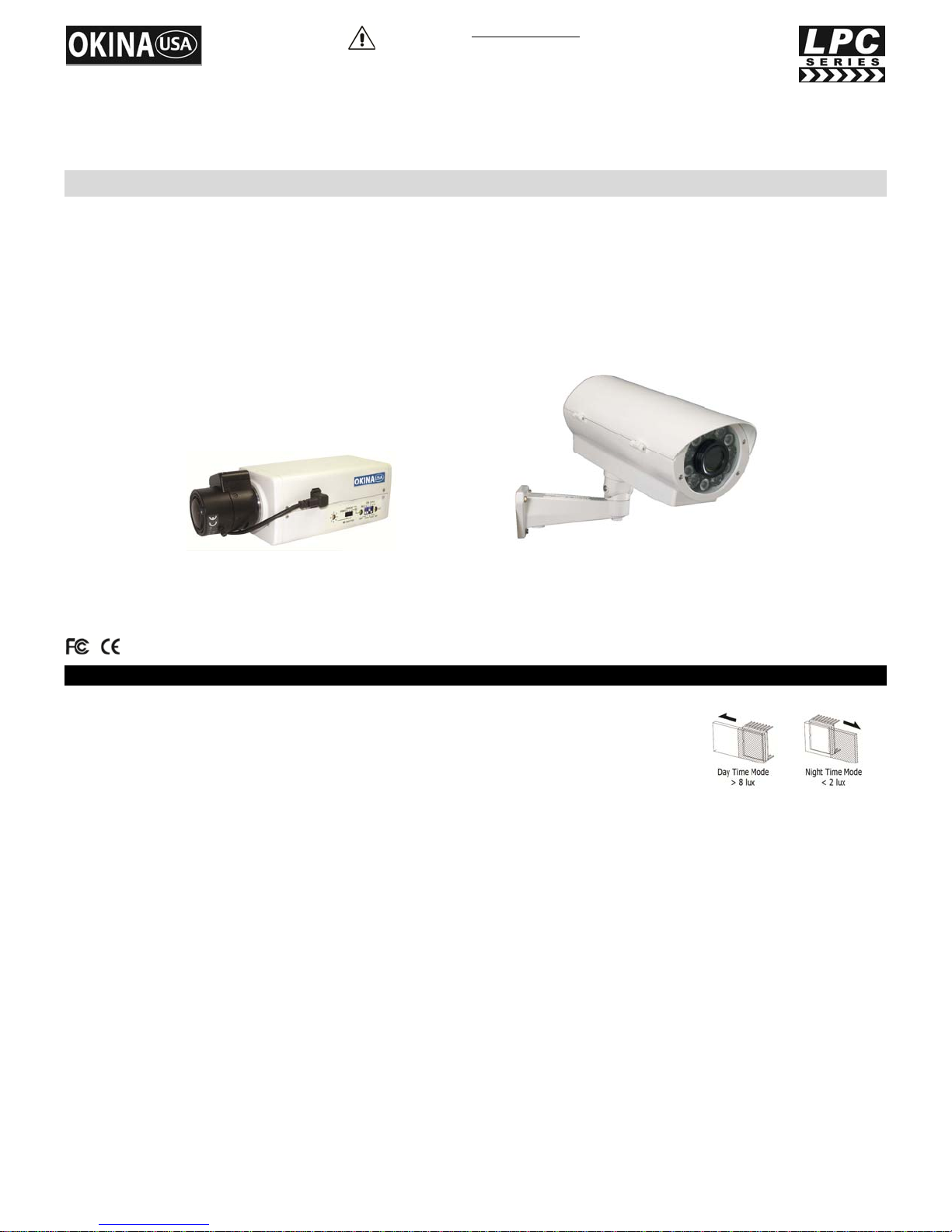
One (1) SHM-7540LPDN-IO/SHM-7540LPDN-IOP Camera
One (1) HI11-TKHBL IR Illuminator Housing
One (1) Fully-Cable Managed Bracket
One (1) Main Accessories Pack
Three (3) Rust-proof Stainless Steel Wall Screws
Three (3) Rust-proof Stainless Steel Mounting Screws
Three (3) Stainless Steel Washers
Three (3) Plastic Washers
One (1) Allen Wrench
One (1) SecondaryAccessories Pack
Three (3) Screw-on Connectors
One (1) Rubber Pad
One (1) Rust-proof Stainless Steel Camera Screw
One (1) Plastic Washer
One (1) Operational Manual
*For any returns, please include all components listed above with original packaging in Resalable Condition. Absolutely No Returns will
be accepted if any component is missing/damaged or if any cable is cut or tampered with.
CAUTIONS
1. Never point the camera toward the sun
Do not expose the lens directly to the sun or to strong light as this may damage the pick-up device.
2. Handle this camera with care
Avoid any shock or bumping of the camera. Improper handling could damage the camera.
3. Requires a proper operating environment
This camera is designed for outdoor or indoor use. The allowable temperature range for operation of this camera is between
14F ~ 122F / -10C ~ 50C and the allowable humidity is 80%RH maximum.
4. Clean the front face to the pick-up device
It is recommended that the pick-up device surface be cleaned before lens installation or whenever the lens is changed. Cleaning should
be done by using a chamois, a very fine soft cloth, lens tissue, or cotton tipped applicator and ethanol to carefully remove any fingerprint
or dust.
5. Check the power source voltage
The power source voltage should be within the specified range. (Camera must meet the specifications). Camera must be connected to a
surge protector at all times.
6. Objects and liquid entry
Never push objects of any kind into this camera as this may touch dangerous voltage points of short out parts that could result in a fire or
electric shock. Never spill any kind of liquid on the video product.
7. Servicing
Do not attempt to service this video product by yourself as opening or removing covers may expose you to dangerous voltage or other
hazards. Refer all service to qualified servicing personnel.
8. Damage requiring service
Unplug this video product from the wall outlet and refer service to qualified servicing personnel under the following conditions:
a. When the power supply cord or plug is damaged.
b. If liquid has been spilled, or objects have fallen into the video product.
c. If the video product has been dropped or the cabinet has been damaged.
d. When the video product exhibits a distinct change in performance.
WARRANTY
OKINAUSA Products are covered under warranty for one year from the date of purchase. The warranty will automatically be voided if any of
the following occurs:
1. Product sticker is removed
If the product sticker is removed, we will not be able to confirm any information regarding when and where the product was purchased. We
have no other way to verify the purchase record without the serial number on the product sticker; therefore, it should not be removed.
2. Product is modified in any way
If the product is scratched, damaged, or modified in a manner not described in this manual, the warranty will be voided immediately. It is
the customer’s responsibility to keep the product in good condition.
3. Power cable is cut
The power cable and any other cable should not be tampered with. Cutting or modifying of the cables will result in termination of the
warranty.