Oktober 7 User manual

OKTOBER CAN SEAMERS
Model 7
Operation Manual
Original Version. January 14, 2020 Oktober Can Seamers 5 Colfax St. NE, Grand Rapids, MI 49505

SET-UP
Check out the how-to videos on our website!
To remove your seamer from its box, lift as shown below. It is heavy (~45lbs) so
use caution while lifting.
Locate your seamer on a flat, level tabletop or bar-height surface. Make sure
there is enough room around the seamer to move around it easily.
Attach the lever arms (located in the accessories box that comes with the seamer)
by threading them into the holes located on the roller housings. !ATTENTION!
Make sure the locking spring washer (wavy washer) is between the handle and
the roller housing and tighten it securely. If the handle’s threads loosen they
will bend or break over time.
!ATTENTION! Canning is done in a wet environment, so always plug the
seamer into a GFCI outlet to avoid shocking hazards.
The power cable is located “under” the seamer inside a 2in opening in the base
plate.
-------------------------------------------------------------------------------------------------------------

!!!SAFETY PRECAUTIONS!!!
-Since canning is likely to create a wet environment, make sure the flooring and
footwear worn around the seamer is non-slip.
-Always plug the seamer into a GFCI outlet to avoid shocking hazards.
-Pay attention to things like loose clothing, long hair, etc. The can and upper and
lower chucks will be spinning and can cause injury if anything gets wrapped
around them.
-Never reach into area around the upper chuck and rollers while operating. The
rollers can pinch or draw-in fingers and objects and cause injury.
-Never remove the top cover while operating. The spinning belt and motor will be
exposed and can cause injury.
-Never remove the switch enclosure box, or the motor connection panel while the
seamer is plugged in. There are open live connections inside each that risk a
shocking hazard.
-------------------------------------------------------------------------------------------------------------
POWER REQUIREMENTS
Short Circuit Current Rating:
115V: 21amps 230V: 10amps
Rated Frequency
115V: 60Hz 230V: 50Hz
Full Load Current
115V: 5.6amps 230V: 2.8amps
-------------------------------------------------------------------------------------------------------------

MODEL 7 SEAMER DIAGRAM

CAPABILITIES
The MODEL 7 Oktober Can Seamer is designed to seam aluminum beverage cans.
Aluminum beverage cans come in many different sizes, and the model 7 can be
configured to seal many of them. Cans with the same “end” size (can top) can
generally be sealed using the same “tooling” set (upper chuck, seaming rollers,
base assembly). Tooling sets are available for end sizes 200, 202, 206, 209, and
300. Each seamer includes one tooling set. Changing tooling sets requires re-
calibration. Each set comes with one or two standard lower adapters. Other
lower adapters are also available, including custom adapters.
Tooling Sets:
A: Size 200 ends. Comes with lower adapter for 250ml cans.
B: Size 202 ends. Comes with lower adapters for 12oz and 16oz cans.
C: Size 202 ends. Comes with lower adapters for 330ml and 500ml cans.
D: Size 202 ends. Comes with lower adapters for 19.2oz and 16oz cans.
E: Size 206 ends. Comes with lower adapters for 24oz cans.
F: Size 209 ends. Comes with lower adapters for 1000ml cans.
G: Size 300 ends. Comes with lower adapters for 32oz cans.
GETTING STARTED
Your seamer comes calibrated and ready to go so you shouldn’t need to adjust
anything. If you do have an issue, check the troubleshooting list at the end of the
manual. There are a few things that may need to be adjusted due to shipping
issues, etc.
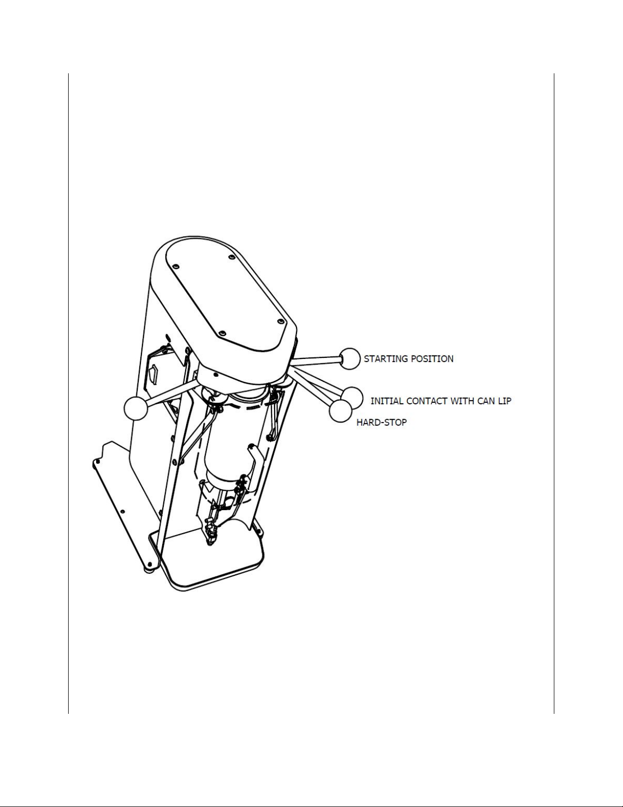
Seaming (check out the how-to videos on our website!)
Seaming is super simple. The basic idea is to rotate the right handle until it
contacts a hard-stop, back it off to its starting position, then do the same for the
left handle. The can spins fast enough that the speed the operation levers rotate
can vary, but you also don’t want to slam the handles. Keep in mind that it
doesn’t take much force to seam a can. As soon as the lever has hit its hard-stop
the operation is completed. Make sure to read through the detailed instructions

below. It is a good idea to run through the steps a few times without a can to get
a feel for it.
Helpful tip: The can-guides (two extended screws below the upper chuck) are
designed to hold the can upright and in the correct position to close the splash
guard door. Set the can onto the lower adapter and lean it back against the
guides. Pull your hand out of the machine and then close the splash guard door.

Make sure the correct adapter is in place for the can size you plan to use.
Adapters generally snap onto the top of the standard adapter like a “LEGO©”
piece.
1. Rotate both operation levers outward to their starting positions.
2. Open the splash guard door by pulling the splash guard handle out and
downward.
3. Set a filled can (and end) onto the lower adapter and rotate the can back into
the seamer. The can should rest against the “Can Guides.” The can should
stay upright on its own once placed against the can guide.
4. Close the splash guard door. It should feel a bit heavy as it clamps the can and
will lock in-place with a solid feeling. *note closing the splash guard will not
feel the same without a can loaded into the seamer.
5. Turn the power switch to the “on” position. The can will start to spin.
6. Rotate the first operation lever (right side of the seamer when facing it) until
the roller makes contact with the edge of the can end.
7. Once the roller makes contact, continue to rotate the lever until it stops. It
should take 1-2 seconds for the roller to rotate between initial contact and the
hard-stop.
8. Once the lever has reached the hard-stop, hold for 1second, then return the
lever to its starting position.
9. Repeat the same process for the second operation lever.
10. Turn the power switch to the “off” position
11. Once the can has stopped rotating, open the splash guard door and remove
the can.
Sometimes it’s helpful to explain the things to NOT do. These include:
Do Not: use the left handle first
Do Not: hold both handles IN at the same time
Do Not: run either operation more than once.
Do Not: go back and do the first operation after the second operation is
completed.
-------------------------------------------------------------------------------------------------------------

Daily Maintenance
-Wipe down the seamer with warm water and a rag to keep it clean of sticky
residue. You can add a small amount of sanitizer or dish soap, but it is NOT
suggested to use other cleaners. Warm water is all that is needed to break up
sticky residues. Make sure to dry everything off thoroughly.
-The Splash Guard can be cleaned more easily by removing the two “ring” quick-
release pins located between the base lever and base shaft. This allows the
handle to be removed from the base and the door to swing away from the seamer
to allow better access to the inner surfaces. You can also lift the base shaft up
and out for better access to the stainless panel for cleaning.
-Make sure to empty and rinse the drip tray often to avoid spills.
Weekly Maintenance
-Pull the white plastic lower adapter off the base shaft bearing and use a rag and
warm water to wipe down the bearing, washer(s) and wave spring (see diagram
above). Dry them off and add a dab of grease into the bearing and rub some onto
the spring and washer(s). Replace them in the same order they were removed.
-Remove the base shaft by pulling out the upper quick-release pin. The shaft can
then be pulled upward and out of the machine. Wipe down the shaft and the
bore that the shaft rides in with water and a rag. Dry them off and rub a dab of
grease onto the shaft. If this isn’t done regularly, the shaft will eventually become
sticky and the splash guard handle will become difficult to close. DO NOT force
the handle if it becomes sticky or you will !BEND OR BREAK! the base adjuster.
Helpful Hint: remove and clean the base shaft at the end of the day and leave the
assembly on the counter next to the seamer so that the morning shift opener sets
it back into the seamer. This way there is a reminder that it is getting cleaned
often.
-------------------------------------------------------------------------------------------------------------

Seam Inspection
Check out our how-to videos on the website!
Our method of seam inspection requires a “tear-down tool,” some nippers or wire
cutters, and a set of calipers. The tear-down tool and calipers are available on the
Oktober website.
When measuring the seam thicknesses, the calipers should be parallel to the
inside taper of the can (as shown below), rather than parallel to the straight sides
of the can.
Make sure to not squeeze the calipers too tightly when measuring. Use the
lightest pressure possible to allow the calipers to close against the seam. If too
much pressure is used, the seam will appear smaller than reality.

1) Complete the first operation ONLY,
remove the can from the seamer, and
measure the first operation seam thickness
as shown.
First Operation Seam Thickness:
Size 200 and 202 ends
.074in - .078in
Size 206 ends
.074in-.078in
Size 300 ends
.104in - .112in
2) Place the can back into the seamer
and run the second operation. Remove the
can and measure the final seam thickness
as shown.
Second Operation Seam Thickness:
Size 200 and 202 ends
.043in - .046in
Size 206 ends
.046in-.050in
Size 300 ends
.064in - .068in
3) Using a tear-down tool, cut the top of
the can off.

4) Using nippers or wire cutters, cut a
notch through the entire remaining seam.
5) Pull the seam out of the can body as
shown. Start from the notch that you cut
with the nippers.
6) Measure the “cover hook length” in
at least 3 places around the inside lip of the
removed seam.
Cover Hook Length:
Size 200 and 202 ends
.053in - .065in
Size 206 ends
.060in -.70in
Size 300 ends
.065in - .085in

7) Measure the “body hook length” in at
least 3 positions around the perimeter of
the can.
Body Hook Length:
Size 200 and 202 ends
.055in - .075in
Size 206 ends
.060in - .080in
Size 300 ends
.072in - .088in
-------------------------------------------------------------------------------------------------------------

Calibration
If any of the measurements from the seam inspection aren’t within the
specifications, it may be time to adjust the seamer’s calibration.
Infeed Calibration
If the first or second operation seam thickness is incorrect, you can adjust them
by adjusting the infeed adjuster screws (see diagram) The adjusting screws and
their locknuts can be accessed with the back cover still attached to the seamer
through access slots. The nut requires a 3/8in wrench and the screw requires a
5/32in allen key.
To decrease the operation seam thickness, loosen the adjuster screw nut, and
turn the screw counterclockwise.
If the seam is too small turn the screw clockwise.
Each rotation adjusts the thickness approximately .001in.
After adjusting the screw, run the operation again and measure the new seam
thickness. Continue to adjust, test, and re-measure until the seam thickness is
within the specification.

Vertical roller position
The gap between the roller and the top surface of the upper chuck needs to be
set to a minimum (see diagram above).
Basically, the gap should be as small as possible, while allowing free rotation of
the roller when it is engaged over the chuck (operation handle is against the hard
stop).
To set the gap, first loosen the vertical position locking screw. The roller assembly
should now be free to move up and down.
Position the roller above the chuck (as shown) by rotating the operation lever to
the hard-stop position.
Allow the roller to rest on the chuck and re-tighten the vertical position locking
screw.
With the roller still located on top of the chuck, rotate it to make sure it doesn’t
get difficult to spin. If it feels tight, loosen the locking screw, and retighten it
slowly while rotating the roller. Repeat if necessary, until the roller spins freely.

Base Force Adjustment
The clamping force between the lower adapter and the upper chuck is critical to a
good seam. In particular, the base force has a significant effect on the seam’s
body hook (more base force typically will create a larger body hook).
In general, the base force is set to just less than the maximum that the can will
take before it collapses. If your cans are denting and/or collapsing when closing
the splash guard door then it is possible that the base force is too high. (Note:
cans that are empty are much more likely to crush than a full can)
Before adjusting the base force, make sure the wave spring and washers are
located correctly inside the lower adapter (see MODEL 7 SEAMER DIAGRAM).
To adjust the base force, first back off the lower base adjuster nut a couple turns.
Note: the lower nut’s function is to take up play in the base adjuster. The upper
nut is used to set the actual base force.
You will need an un-seamed can and end to set the base force.
Turning the upper base adjuster nut clockwise will increase the base force, while
turning it counterclockwise will decrease it.
To RESET the base force:
1) With a can loaded into the seamer, use the upper nut to lower the base
force to nearly zero. As you adjust the nut, the handle will feel lighter and lighter
until the can never fully clamps. Its helpful to disconnect the splash guard from
the handle.
2) Once the force is set to zero, rotate the upper nut:
1-5/6 turns for 200 and 202 ends (11-12 “flats” of the side of the nut)
2-5/6 turns for 206 ends (16-18 “flats” of the side of the nut)
2-1/2 turns for 300 ends (15-16 “flats” of the side of the nut)
3) Snug up the lower base adjuster nut
4) Test a can by seaming it and measuring the body hook. If it is sufficient
then the base force is also sufficient.

-------------------------------------------------------------------------------------------------------------
Changing Tooling
To change between different end sizes, you will need to swap out the upper
chuck, 1st and 2nd operation roller assemblies, the base shaft assembly, and the
can guide spacers. You will also need to re-calibrate the base force and roller
positions (see instructions above).
Upper Chuck
-First remove the top cover.
-Remove the drive belt by pushing an edge of it off the large pulley and spinning
that pulley by hand. The belt should slide off easily.
-loosen the set screw located on the side of the large pulley
-remove the large pulley’s locknut. Make sure to hold onto the upper chuck while
removing the nut to make sure the chuck doesn’t fall out of the bearings.
-Pull the upper chuck down and out of the bearings. Pay attention to the
orientation of the bearings, as they must face a certain direction.

This side faces out This side faces the inside of the housing
-Place the new upper chuck into the bearings and housing. The chuck fits very
precisely into the bearings but should slide in without a lot of force. Don’t force
the chuck into the bearings or it can get stuck.
- See diagram below. Reassemble the washers and spring washer and pulley as
shown. Make sure the concave side of the spring washer faces down.
-Thread on the Locknut and tighten it by hand.
-Lightly tighten the pulley set screw onto the flat surface on the side of the upper
chuck.
-Tighten the pulley locknut just enough to flatten the spring washer.
-Replace the belt by first placing it over the small pulley, then pull it over the large
pulley while rotating the pulley by hand.

Roller Assemblies
-Loosen both vertical adjust locking screws.
-Remove the roller assembly retaining nuts and pull the roller assemblies down
and out of the housing.
-Rub a small amount of grease onto the roller assembly axle and place the new
roller assemblies up and into the housing. Make sure the brass washers are
oriented as shown below.
-Loosely re-tighten the roller assembly retaining nut until you feel a slight drag
when rotating the roller assembly arm. DO NOT OVERTIGHTEN.
Base Shaft Assembly and Can Guide Spacers
-Remove the base shaft assembly by removing the upper quick release pin and
pulling the shaft up and out of the housing. Replace with the new assembly.
-Remove the two button head screws retaining the can guide spacers and replace
them with the new spacers.

Other Maintenance
Seaming Rollers:
The bearings in the seaming rollers are oil-impregnated bronze bearings and are
nearly maintenance free. If the rollers become sticky, they probably need to be
thoroughly rinsed with water to break up the sticky residue.
In extreme cases, you can remove the entire roller assembly out of the seamer
and soak it in warm water (see diagram above). 15 minutes should be enough to
loosen up sticky residues. Work the roller by hand until it becomes free and easy
to rotate. Dry everything off and add a few drops of food-safe oil (like super-lube)
above and below the roller. Spin the roller to work the new oil into the bearing
and its axle.
Re-assemble as described above.
Troubleshooting
Can does not spin when seamer is turned on
Sometimes during shipping, the motor gets displaced enough for the drive belt to
slip off the pulleys. Unplug the seamer and remove the top cover and check to
make sure the belt hasn’t fallen off the pulleys. If it has, you should be able to slip
the belt back on by first placing the belt over the small pulley, then pull it over the
large pulley while rotating the pulley by hand.
If the belt continues to fall off after
it has been placed back on the
pulleys, you may need to align the
driver pulley. This can happen when
the box is dropped during shipping
and the motor becomes misaligned,
but it is easy to fix. There is a small
set screw on the side of the pulley.
Loosen the set screw and raise or-

lower the pulley to be in-line with the larger pulley. Tighten the screw, place the
belt onto the pulleys, and test by spinning the large pulley by hand. If the belt
stays on both pulleys it is aligned properly.
If the seamer does not turn on, it may be because either the thermal overload
switch (located on the bottom of the motor) or circuit breaker (white button
located on the backside of the electrical box) has tripped. You will need to
remove the seamer’s back cover to access the motor’s thermal switch. The circuit
breaker is a white button on the bottom of the switch housing. Pushing either of
these reset buttons in will reset them. One common cause for them tripping is
pulling both operation levers at the same time.
Table of contents
Popular Commercial Food Equipment manuals by other brands

Diamond
Diamond 65/40 FTE operating instructions

Lotus
Lotus FT 74 ET X Series Installation and operating instructions

Taylor
Taylor Taylormate 152 Operation

Middleby
Middleby CTX Mighty Chef TCO2114 Owner's operating & installation manual

Unified Brands
Unified Brands Randell DPM Series Operator's manual

LYSON
LYSON W370 manual