Oldenbourg group euv-400 Quick start guide

EUV-400 ELECTRIC UTILITY VEHICLE
PARTS AND SERVICE MANUAL
PUB. NO. 1486
©
2010 All rights reserved.
OLDENBURG ELECTRIC UTILITY VEHICLE INCLUDES:
25 HP OLDENBURG ELECTRIC AC MOTOR
HEAVY DUTY DANA 44 DRIVE AXLES
FRONT AND REAR DISC BRAKES
ATLAS TRANSFER CASE
FLUX VECTOR VARIABLE SPEED AC DRIVE
DIGITAL GRAPHIC DISPLAY
REMOVABLE BATTERY PACK WITH QUICK DISCONNECT
with AMP Electric Drive
Revision2November2010


i
TABLE OF
CONTENTS
TABLE OF CONTENTS
Section Page
1 INTRODUCTION
General Description........................................................................................................................ 1-2
Required Working Space................................................................................................................ 1-2
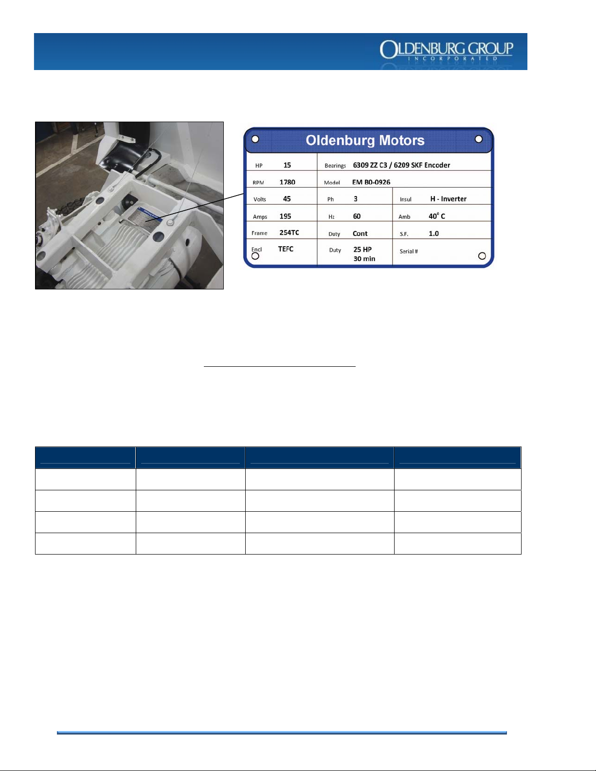
Machine Specifications................................................................................................................... 1-3
Component Serial Numbers ........................................................................................................... 1-4
2 SAFETY
Machine Misuse.............................................................................................................................. 2-2
Recognize Safety Information......................................................................................................... 2-2
Understand Signal Words............................................................................................................... 2-4
Safety Precautions.......................................................................................................................... 2-4
Battery Safety ................................................................................................................................. 2-8
3 PARTS
Introduction..................................................................................................................................... 3-2
Electric Utility Vehicle (EUV)........................................................................................................... 3-5
Electrical Group .............................................................................................................................. 3-7
Motor Group.................................................................................................................................... 3-12
Battery Group.................................................................................................................................. 3-13
Wheel Group................................................................................................................................... 3-14
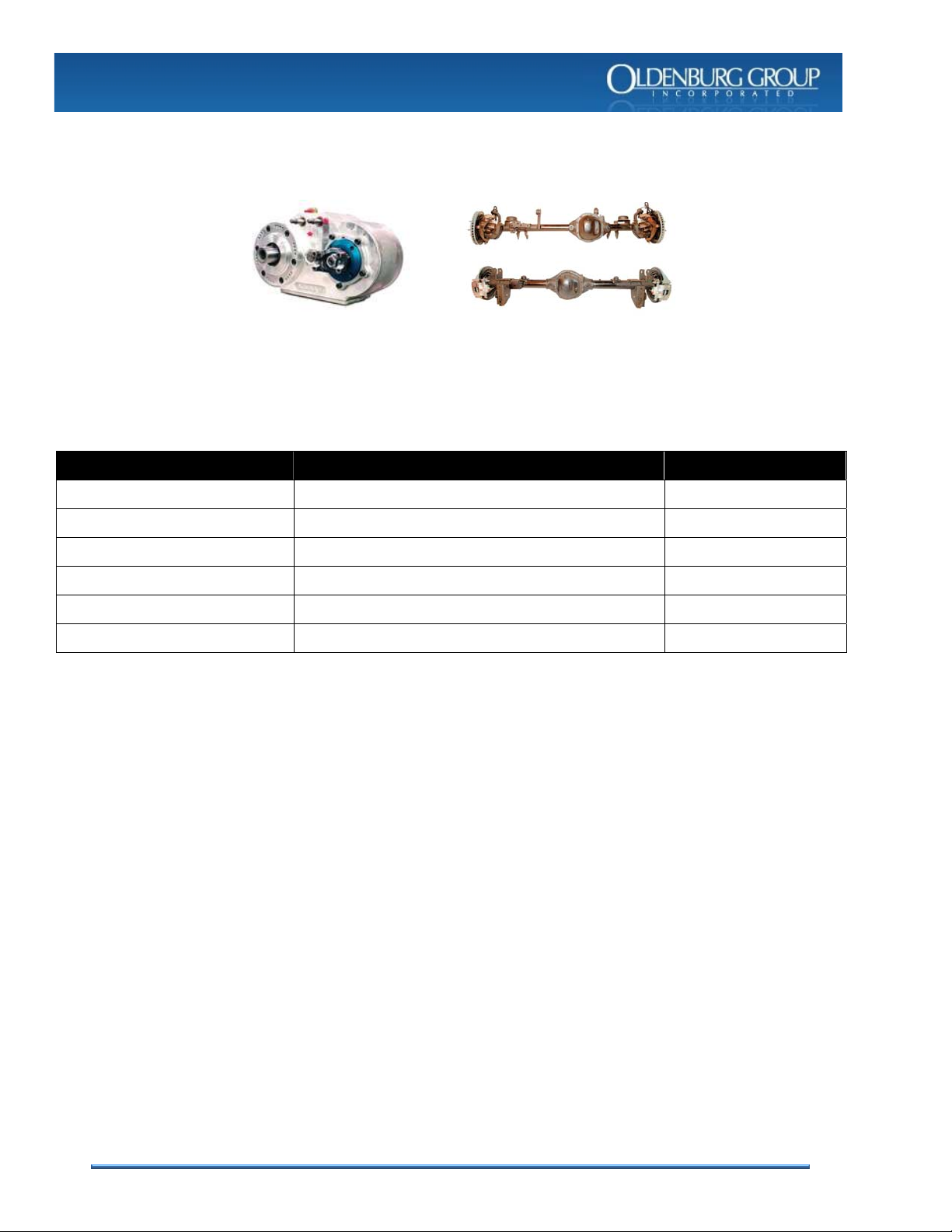
Drop Box Group.............................................................................................................................. 3-15
Axle & Suspension Group............................................................................................................... 3-16
Steering Group................................................................................................................................ 3-19
Driveline Group............................................................................................................................... 3-20
Brake Group.................................................................................................................................... 3-21
Options............................................................................................................................................ 3-23
4 SERVICE
Cleaning.......................................................................................................................................... 4-2
Storage ........................................................................................................................................... 4-2
General Service.............................................................................................................................. 4-3
Service Intervals ............................................................................................................................. 4-7
Service Lubrication ......................................................................................................................... 4-8
Recommended Fluids..................................................................................................................... 4-10
Torque Table................................................................................................................................... 4-10
Electrical Schematic........................................................................................................................ 4-11
Electrical Wiring Diagram................................................................................................................ 4-12

ii
TABLE OF
CONTENTS
ORIGINAL EQUIPMENT MANUFACTURERS
The following table lists the various original equipment manufacturer components, the documentation or literature
provided, and the source of the documentation.
These documents are provided electronically in Portable Document Format (PDF) and are included on the CD
provided with your manual.
COMPONENT DOCUMENT(S) SOURCE
Oldenburg AC Electric Motor How To Get The Most From Electric Motors EASA
Atlas Transfer Case Specifications and Instructions Guide Advance Adapters Inc.
Dana Drive Axles Illustrated Parts Lists and Service Manual Dana / Roadranger
Sevcon Motor Controller Applications Reference Manual Sevcon
SKF Sensor-Bearing Unit Product Data Manual SKF
Industrial Battery Charger Installation and Operation Manual Crown

1-1
SECTION 1
INTRODUCTION
This manual contains all the information necessary to identify common service parts and safely maintain your
Oldenburg Group Incorporated machine. This manual is an important part of your machine and should remain
with the machine.
Reading your manual will help you avoid personal injury or damage to the machine. Information given in this
manual will provide you with the safest and most effective parts identification and service information for your
machine.
The machine shown in this manual may differ slightly from your machine, but will be similar enough to help you
understand our instructions. Right and left sides are determined by facing in the direction the machine will
travel when going forward.
New personnel must be thoroughly trained by qualified personnel and must never service the machine
unsupervised. Information in this manual must be reviewed and understood before using this machine. Failure
to comply could result in serious injury or damage to the machine.
The manufacturer accepts no liability for damage or injury resulting from machine misuse, and these risks must
be borne solely by the user. Compliance with and strict adherence to the conditions of operation, service and
repair as specified by the manufacturer also constitute essential elements for the intended use.
This utility vehicle should be operated, serviced and repaired only by persons familiar with all its particular
characteristics and acquainted with the relevant safety rules (accident prevention). The accident prevention
regulations, all other generally recognized regulations on safety and occupational medicine and the road traffic
regulations must be observed at all times.
Read and understand
manual and safety
information before
operating!

1-2
SECTION 1
INTRODUCTION
GENERAL DESCRIPTION
The Oldenburg Electric Utility Vehicle (EUV-400) is an AC electric motor driven utility vehicle with an off-highway
application driveline including Dana drive axles and an Atlas transfer case. The machine has a front and rear disc
hydraulic service brake system, cab operated parking brake, and emergency driveline brake. The machine has a
500 lb payload capacity and spare battery pack.
REQUIRED WORKING SPACE
Machine turn radius of
4.68 meters (184 inches).

1-3
SECTION 1
INTRODUCTION
MACHINE SPECIFICATIONS
The machine is designed to be used underground but may also be used on the surface. If the machine is to be
used on the surface it shall not be used during inclement weather that may affect the safe operation of the
machine. The machine shall not be used anytime lighting is present. Refer to the table below for ambient
temperature and humidity limitations.
It is important to keep the machine clean for safe operation. Dirt and mud can build up on surfaces causing an
unsafe condition. It is also important to keep the machine clean for proper operation of the moving components
and for serviceability of the machine.
Length 144 inches
Width 63 inches
Height 81.5 inches
Weight pounds 4,320
Electric Motor Oldenburg 25 HP AC (30 min. rating)
Outside Turning Radius 16’-8.1” (>3.3”)
Payload pounds 500 lbs
Maximum Speed 6.5 mph
Maximum Gradient Angle 25%
Ambient Temperature Limits 0° TO 37°C (33° TO 100°F)
Relative Humidity Limit 95%
Battery Indicator Yes
Digital AC Drive Inverter Yes
Ground Clearance 9 inches
Machine Electrical Safety Authority
(ESA) certification information is
listed inside the main disconnect
access cover.

1-4
SECTION 1
INTRODUCTION
COMPONENT SERIAL NUMBERS
The following is a list of major components of the Electric Utility Vehicle (EUV). Refer to the Parts section of this
manual to identify these components. Locate the component data plate on each component and record the
manufacturer name, part or model number, and serial number.
EQUIPMENT MANUFACTURER PART OR MODEL NUMBER SERIAL NUMBER
AC MOTOR OLDENBURG
FRONT AXLE DANA
REAR AXLE DANA
TRANSFER CASE ADVANCE ADAPTERS
PLEASE HAVE UNIT AND COMPONENT SERIAL NUMBERS WHEN ORDERING
For proper notification of all updates and bulletins, please complete Original Equipment
Manufacturer product registration for all applicable machine components.
A component data plate is attached to major machine
components. This is an example of what the electric
motor data plate looks like and what information is
included on the data plate.

2-1
SECTION 2
SAFETY
This section of the manual contains all safety information for your machine, including special messages to bring
attention to potential safety concerns, machine damage, as well as helpful servicing information. Please read
all the information carefully to avoid injury or damage to the machine.
New personnel must be thoroughly trained by qualified personnel and must never service the machine
unsupervised. Information in this manual must be reviewed and understood before using this machine. Failure
to comply could result in serious injury or damage to the machine.
In addition to all safety measures outlined in this manual, personnel shall adhere to all applicable workplace
practices and regulations. To maintain optimum performance from this equipment, any questions concerning
this publication should be directed to the manufacturer.
Read and understand
manual and safety
information before
operating!

2-2
SECTION 2
SAFETY
MACHINE MISUSE
DO NOT USE THIS MACHINE TO…
TOW OTHER MACHINES OR MACHINERY
OPERATE IN EXPLOSION HAZARDOUS ATMOSPHERES
DRIVE ON PUBLIC ROADWAYS
RECOGNIZE SAFETY INFORMATION
These are some of the safety-alerts labeled on your machine. When you see these, you must be alert to the
potential for personal injury if instructions are not followed properly.
The following labels are critical to the safety of personnel operating or servicing the machine. Review these
and fully understand these prior to operating the machine or performing any service on the machine.
Brake Test
Park Brake

2-3
SECTION 2
SAFETY
Seat Belts
Battery Disconnect
Battery Disconnect

2-4
SECTION 2
SAFETY
UNDERSTAND SIGNAL WORDS
The signal words DANGER, WARNING, or CAUTION are used with the safety-alert symbol. Each covers a
different level of probability or severity.
A Danger identifies the most serious hazards that will result in serious injury or death.
A Warning identifies critical hazards that could result in serious injury or death.
A Caution identifies potential hazards that could result in minor injury.
A Notice identifies the potential for major damage to the machine or other equipment.
SAFETY PRECAUTIONS
FOLLOW SAFETY INSTRUCTIONS
Carefully read all safety messages in this manual and on your machine safety signs. Keep safety signs in good
condition. Replace missing or damaged safety signs.
Keep your machine in proper working condition. Unauthorized modifications to the machine may impair the
function and safety, and affect machine service life.
WEAR PROTECTIVE CLOTHING AND PROTECTIVE DEVICES
Wear close fitting clothing and safety equipment appropriate to the job. This may include, but not be limited to
the following items: Eyewear, gloves, hardhat, steel-toe boots, and hearing protection.
Prolonged exposure to loud noise can damage your hearing. Wear suitable hearing protection such as
earmuffs or earplugs to protect against loud noise.
Operating equipment safely requires the full attention of the operator. Do not wear radio or music headphones
while operating machine.
PREPARE FOR EMERGENCIES
Be prepared if a fire starts.
Keep a first aid kit and fire extinguisher handy.
Keep emergency numbers for doctors, ambulance service, hospital, and fire department near the telephone.

2-5
SECTION 2
SAFETY
HANDLE SAFELY - AVOID FIRES
Prevent fires by keeping machine clean of accumulated grease, and debris.
Store flammable fluids away from fire hazards. Do not incinerate or puncture pressurized containers.
Do not store oily rags; they can ignite and burn spontaneously.
Keep all fire extinguishers in operational condition.
Alert mine personnel of any fire hazards.
USE CAUTION WHEN WELDING
Disconnect batteries prior to performing any welding procedure.
Disconnect all cables and wiring to the Sevcon motor controller
prior to performing any welding procedure.
Always use proper protective clothing and devices when welding.
STAY CLEAR OF ROTATING DRIVELINES
Be alert when working around rotating drivelines. Entanglement in rotating driveline can cause serious injury or
death.
Tie long hair behind your head. Do not wear a neck tie, scarf, necklace, or loose fitting clothing when working
around operating machine. These items can get caught and pull you into moving parts, resulting in severe injury
or death.
Stop engine and be sure driveline is stopped before performing maintenance.
PRACTICE SAFE MAINTENANCE
Understand service procedure before doing work. Read appropriate technical manual first. Keep work area
clean and dry.
Never lubricate or service machine while it is operating or moving. Keep hands, feet, hair, and clothing clear of
rotating parts. Disengage all power and operate controls to relieve pressures. Lower equipment to the ground.
Stop the engine and allow machine to cool.
Securely support any machine components that must be raised for service.
Keep all parts in good condition and properly installed. Fix damage immediately. Replace worn or broken parts.
Remove any buildup of grease, oil, dirt, or debris.
Disconnect battery before performing any maintenance on electrical system.

2-6
SECTION 2
SAFETY
AVOID HIGH-PRESSURE FLUIDS
Escaping high pressure fluid can penetrate skin, causing serious injury.
Relieve pressure before disconnecting hydraulic or other pressure lines. Tighten all connections before
restoring system pressures.
Do not use hands to feel for leaks. Search for leaks with a piece of cardboard.
If an accident occurs, see a doctor immediately. ANY fluid injected into the skin must be surgically removed as
soon as possible or gangrene may result.
USE PROPER LIFTING EQUIPMENT
Lifting heavy components incorrectly can cause severe injury or machine damage.
Never work under suspended loads with out safety devices in place.
DISPOSE OF WASTE PROPERLY
Improperly disposal of waste can damage the environment and ecology. Potentially harmful waste can include
such items as oil, brake fluid, hydraulic fluid, and batteries.
Use leak-proof containers when draining fluids. Do not use beverage containers that may mislead someone
into drinking from them.
Do not pour waste onto the ground, down the drain, or into any water source.
Air conditioning refrigerants escaping into the air can damage the Earth's atmosphere. Recover and recycle
refrigerants when servicing the air conditioning system.
HANDLE CHEMICALS SAFELY
Direct exposure to hazardous chemicals can cause serious injury. Potentially hazardous chemicals used with
Cannon equipment include such items as hydraulic fluid, lubricants, coolants, and paints.
A Material Safety Data Sheet (MSDS) provides specific details on chemicals: physical and health hazards,
safety procedures, and emergency response techniques.
Check the MSDS before starting any job using a chemical, to know exactly what the risks are and how to do
the job safely.

2-7
SECTION 2
SAFETY
PREVENT MACHINE MOVEMENT
ALWAYS chock wheels before performing any maintenance.
Whether parked on an incline or flat surface, always take the necessary precautions to prevent the vehicle
from rolling. Do not rely exclusively on the park brake to hold the vehicle in place.
Also place the parking brake in the locked position prior to performing any maintenance.
TIRE SAFETY
Explosive separation of a tire and rim
parts can cause serious injury or death.
Do not attempt to mount a tire without
the proper equipment and experience
to perform the job.
Always maintain the correct tire pressure. Do not inflate the tires above the recommended pressure. Never
weld or heat a wheel and tire assembly. The heat can cause an increase in air pressure resulting in a tire
explosion. Welding can structurally weaken or deform the wheel.
When inflating tires, use a clip-on chuck and extension hose long enough to allow you to stand to one side
and NOT in front of or over the tire assembly.
Check tires for low pressure, cuts, bubbles, damaged rims or missing lug bolts and nuts.
RIDERS CAN FALL OFF AND BE KILLED
Seating is provided for operator and one
passenger. No riders are allowed in cargo
box or anywhere else on vehicle.
Riders on vehicle are subject to injury such as being struck by foreign objects or being thrown off of the
vehicle and severely injured or killed.
Riders affect the operator's ability to control the vehicle as well as its center of gravity. Also, riders could
obstruct the operator's view resulting in the vehicle being operated in an unsafe manner.
Never allow riders in the cargo box or other areas where seats are not provided.
ROLLOVER OR FALLING OFF MAY CAUSE DEATH
Read manual carefully.
No loads heavier than the rated load for this machine.

2-8
SECTION 2
SAFETY
PARK VEHICLE SAFELY
Always stop the vehicle on a level surface.
Set and lock park brake.
Do not exit operators seat until all moving parts are stopped.
Verify main disconnect is off.
BATTERY SAFETY
Absorbed Glass Mat (AGM) is a version of the lead acid battery. The AGM batteries are specialty batteries that
typically cost twice as much as a premium wet cell. However they store very well and do not tend to sulfate or
degrade as easily as wet cell. There is little chance of a hydrogen gas explosion or corrosion when using these
batteries; these are the safest lead acid batteries you can use. Some AGM batteries may require a special
charging rate. If you want the best, most versatile type, consideration should be given to the AGM battery. If you
don't use or operate your equipment daily, AGM batteries will hold their charge better that other types. There is a
some common confusion regarding AGM batteries because different manufactures call them by different names;
some of the more common names are "sealed regulated valve", "dry cell", "non spillable", and "Valve Regulated
Lead Acid" batteries. In most cases AGM batteries will give greater life span and greater cycle life than a wet cell
battery.
The Absorbed Glass Matt construction allows the electrolyte to be suspended in close proximity with the plates
active material. In theory, this enhances both the discharge and recharge efficiency. Common manufacturer
applications include high performance engine starting, power sports, deep cycle, solar and storage battery. The
larger AGM batteries we sell are typically good deep cycle batteries and they deliver their best life performance if
recharged before allowed to drop below the 50% discharge rate.
Battery Do's:
Think Safety First.
Do read battery safety section.
Do regular inspection and maintenance especially in hot weather.
Do recharge batteries immediately after discharge.
Do buy the highest RC reserve capacity or AH amp hour battery that will fit your configuration.
Battery Don'ts:
Don't forget safety first.
Don't add new electrolyte (acid).
Don't use unregulated high output battery chargers to charge batteries.
Don't place your equipment into storage without some type of device to keep the battery charged.
Don't disconnect battery cables while the motor is running (your battery acts as a filter).
Don't put off recharging batteries.
Don't add tap water as it may contain minerals that will contaminate the electrolyte.
Don't discharge a battery any deeper than you possibly have to.
Don't let a battery get hot to the touch and boil violently when charging.
Don't mix size and types of batteries.

2-9
SECTION 2
SAFETY
Follow safety Warning labeled on battery disconnect door
Follow safety Warning labeled on battery pack

2-10
SECTION 2
SAFETY
Battery Safety Information:
There are four main safety hazards associated with the use of any AGM battery. These hazards are:
a) Release of ignitable gas
b) Exposure to acid
c) Shorting of terminals
d) Thermal runaway.
This section provides a description of each of these hazards and means to mitigate them.
A. Release of Ignitable Gasses
All AGM batteries produce hydrogen and oxygen gases during normal charging. Even though these
batteries are designed to recombine these gases internally, the recombination efficiency is less than
100%. Small amounts of hydrogen and oxygen are released from the pressure relief valve during
charging. Normally, the hydrogen gas dissipates very rapidly and never reaches a concentration level
that is hazardous. However, if the battery is installed in an enclosure with minimal airflow, the
concentration of hydrogen could build up to a high enough concentration to be of concern. Hydrogen can
ignite at concentrations as low as 4% in air. For this reason, never install a AGM battery in a sealed or
an airtight container.
B. Exposure to Acid
All lead acid batteries contain sulfuric acid in the electrolyte, which can cause chemical burns to body
tissue. Although AGM batteries are classified as Nonspillable, exposure to the electrolyte is possible
under extreme conditions (e.g., if the battery is cracked open or crushed). In the event that electrolyte is
displaced from the battery, avoid contact with the skin, eyes and clothing. In the event of an accident,
flush with water and call a physician immediately.
C. Shorting of Terminals
AGM batteries have very low internal impedance and therefore are capable of delivering high currents if
the external terminals are short circuited. The resulting heat can cause severe burns and is a potential
fire hazard. Accidentally placing metal objects across the terminals can result in severe skin burns. It is a
good practice to remove all metallic items such as watches, bracelets and rings when installing or
servicing batteries. As a further precaution, insulating gloves should be worn and only insulated tools
should be used when installing or servicing batteries.
D. Thermal Runaway
Thermal runaway is a condition in which the battery temperature increases rapidly resulting in extreme
overheating of the battery. Under rare conditions, the battery can melt, catch on fire, or even explode.
Thermal runaway can only occur if the battery is at high ambient temperature and/or the charging
voltage is set too high. As the battery accepts current, its internal temperature rises. The rise in
temperature reduces the battery impedance, causing it to accept more current. The higher current
further heats the battery, and so on, causing the battery temperature to “runaway”. An upper limit will
eventually be reached when the electrolyte starts to boil, but once the electrolyte has boiled away, the
temperature can climb even further to the point of plastic meltdown and possible fire.
Currently, manufacturers are not aware of any AGM batteries that have failed due to thermal runaway.
To preclude the possibility of thermal runway, the battery charging instructions provided in the service
section should be carefully followed, especially if the battery will be subjected to high ambient
temperatures. Batteries should not be installed near heat sources or in direct sunlight that may artificially
elevate their temperature. Also, there should be adequate air circulation around the batteries to prevent
heat build-up.

3-1
SECTION 3
PARTS
This section of the manual contains the information necessary to locate and identify common service parts. The
parts introduction provides guidance to help navigate this section and identify parts. This section includes
illustrated parts breakdowns, starting with the overall machine and including all major parts groups and
components.
This section does not include common hardware or wiring, rather it is focused on providing parts information for
maintenance significant parts, which are those items likely to be stocked as spare parts or are more likely to be
replaced during repair.
Read and understand
manual and safety
information before
operating!

3-2
SECTION 3
PARTS
PARTS INTRODUCTION
This section provides an illustrated parts breakdown of maintenance significant service parts. The first illustration
is that of the Electric Utility Vehicle, which identifies each major group of parts.
Major
Parts
Group
Table of contents