Oldham OLCT 200 User manual

USER MANUAL
OLCT 200
Gas Detection
Transmitter
P/N: 77036007-1
Revision: 6.2
Reference Firmware: 3.01 (wired rev. 3.2)
Reference Firmware: 3.09 (wireless rev. 1.3)
Reference Firmware: 3.09 (wireless rev. 2.4)
The Fixed Gas Detection Experts

OLCT 200 User Manual | 2
Copyright Feb-2015 by Oldham S.A.S.
All rights reserved. No reproduction of all or part of this document, in any
form, is permitted without the written consent of Oldham S.A.S.
All of the information that is provided in this document is accurate to the best
of our knowledge.
As a result of continuous research and development, the specifications of
this product may be changed without prior notice.
Oldham S.A.S
Rue Orfila
Z.I. Est –C.S. 20417
F–62027 ARRAS Cedex
Tel.: +33 (0)3 21 60 80 80
Fax: +33 (0)3 21 60 80 00
www.oldhamgas.com

OLCT 200 User Manual | 3
THE INFORMATION CONTAINED IN THIS MANUAL IS ACCURATE TO OUR
KNOWLEDGE.
As a result of continuous research and development, the specifications of this product
may be modified at any time without prior notice.
IMPORTANT INFORMATION
The modification of the material and the use of parts of an unspecified origin shall
entail the cancellation of any form of warranty.
The use of the unit has been projected for applications specified in the technical
characteristics. Exceeding the values cannot in any case be authorized.
LIABILITY
Neither Oldham nor any other associated company can be held liable for any
damages, including, without limitations, damages for the loss or interruption of
manufacture, loss of information, defect of the OLCT 200 unit, injuries, loss of time,
financial, or material loss, or any direct or indirect consequence of loss occurring in the
context of the use or impossibility of use of the product, even in the event that Oldham
has been informed of such damage.
SAFETY INSTRUCTIONS
Labels intended to remind you of the principal precautions of use have been placed on
the unit in the form of pictograms. These labels are considered an integral part of the
unit. If a label falls off or becomes illegible, see to it that it is replaced.
Warning: Read & understand contents of this manual prior to
operation. Failure to do so could result in serious injury or death.

OLCT 200 User Manual | 4

OLCT 200 User Manual | 5
Table of Contents
SECTION 1 - SAFETY INFORMATION ........................................................ 7
1.1 Safety Information –Read Before Installation & Applying Power...................... 7
SECTION 2 - INSTALLATION INSTRUCTIONS .......................................... 9
2.1 Introduction........................................................................................................ 9
2.2 Ratings and Certifications................................................................................ 11
2.3 Sensor Location............................................................................................... 11
2.4 Mounting the Enclosure................................................................................... 11
2.5 System Design Specifications ......................................................................... 16
2.6 Field Wiring Installation ................................................................................... 17
2.7 Alarms / RS-485 Modbus 10-0234 Option Installation..................................... 25
2.8 Isolated 4-20mA Output 10-0250 Option......................................................... 26
2.9 HART Communication 10-0351 Option........................................................... 27
2.10 Sensor Installation........................................................................................... 30
2.11 “Sensor Type” and OLCT 200 Signal Conditioning.......................................... 31
SECTION 3 - INITIAL START-UP............................................................... 33
3.1 “Transmitter Configuration” Menu.................................................................... 33
3.2 Initial Bridge Sensor Monitor Start-Up............................................................. 34
3.3 Initial Toxic / Oxygen Sensor Monitor Start-Up................................................ 35
SECTION 4 - OPERATING INSTRUCTIONS ............................................. 37
4.1 Routine Sensor Calibrations............................................................................ 37
4.2 ALARM OPERATION...................................................................................... 40
SECTION 5 - SETUP MENU CONFIGURATION........................................ 41
5.1 Menus Database Configuration....................................................................... 41
5.2 Configuration Using the Magnetic Wand......................................................... 42
5.3 System Configuration Menus .......................................................................... 43
5.4 Alarm Settings................................................................................................. 46
5.5 Sensor Information.......................................................................................... 47
5.6 CLOCK/DELAY SETUP .................................................................................. 48
5.7 LCD Contrast Adj............................................................................................. 49
5.8 HELP Screen................................................................................................... 49
5.9 Diagnostics...................................................................................................... 49
5.10 RS-485 / MODBUS SETUP............................................................................. 50
5.11 SYSTEM SECURITY....................................................................................... 54
SECTION 6 - WIRELESS COMMUNICATION............................................ 55
6.1 Description of Client and Server Wireless Networks ....................................... 55

OLCT 200 User Manual | 6
6.2 OLCT 200 Radio Status (RS) Icons Zzz’s, , , , ............................ 55
6.3 RF Comm Cycle and Power Consumption...................................................... 56
6.4 #10-0299 OLCT 200 Battery I/O PCB with Power Switch ............................... 57
6.5 WIRELESS COMMUNICATION SETUP......................................................... 57
SECTION 7 - TECHNICIANS ONLY MENUS ............................................. 63
7.1 Introduction...................................................................................................... 63
7.2 Set Balance / Set Sensor Voltage (Technicians only!) .................................... 64
7.3 Set Gain to Unity (Technicians only!) .............................................................. 65
7.4 PreAmp Gain Adjust (Technicians only!)......................................................... 65
7.5 Zero Cal Value (Technicians only!).................................................................. 66
7.6 Raw Min / Max Counts (Technicians only!) ..................................................... 66
SECTION 8 - ARCTIC CONFIGURATIONS ............................................... 67
8.1 ARCTIC Option................................................................................................ 67
SECTION 9 - SENSORS ............................................................................. 69
9.1 Catalytic Bead (LEL) Sensors ......................................................................... 69
9.2 Infrared (IR) Sensors....................................................................................... 69
9.3 Photoionization Detection (PID) Sensors ........................................................ 72
9.4 Electrochemical Sensors................................................................................. 76
9.5 Spare Sensors................................................................................................. 77

7
OLCT 200 User Manual | 7
SECTION 1 - SAFETY INFORMATION
1.1 Safety Information –Read Before Installation &
Applying Power
IMPORTANT
Users should have a detailed understanding of OLCT 200 operating and maintenance instructions. Use
the OLCT 200 only as specified in this manual or detection of gases and the resulting protection provided
may be impaired. Read the following WARNINGS prior to use.
WARNINGS
Calibrate with known target gas at start-up and check on a regular schedule, at least every 90
days. More frequent inspections are encouraged to spot problems such as dirt, oil, paint,
grease or other foreign materials on the sensor head.
Do not paint the sensor assembly or the transmitter.
Do not use the OLCT 200 if its enclosure is damaged or cracked or has missing components.
Make sure the cover, internal PCB’s and field wiring are securely in place before operation.
Use only a sensor assembly compatible with the OLCT 200 and approved by Oldham. (See
the section 9.5 for Replacement Parts.)
Periodically test for correct operation of the system’s alarm events by exposing the monitor to a
targeted gas concentration above the High Alarm set point.
Do not expose the OLCT 200 to electrical shock or continuous severe mechanical shock.
Protect the OLCT 200 from dripping liquids and high power sprays.
Use only for applications described within this manual.
Oxygen deficient atmospheres may cause combustible gas readings that use catalytic LEL
sensors to be lower than actual concentrations.
Oxygen enriched atmospheres may cause combustible gas readings that use catalytic LEL
sensors to be higher than actual concentrations.
Calibrate the catalytic combustible gas sensor after each incident where the combustible gas
content causes the instrument to enter in the OVER-RANGE alarm condition.
Silicone compound vapors may affect the catalytic combustible gas sensor and cause readings
to the combustible gas to be lower than actual gas concentrations. If the sensor has been used
in an area where silicone vapors were present, always calibrate the instrument before
continued use to ensure accurate measurements.
Sensor openings must be kept clean. Obstruction of the sensor openings may cause readings
to be lower than actual gas concentrations.
Sudden changes in atmospheric pressure may affect gas readings.
CALIBRATION ALERT: Gas detection instruments are potentially life-saving devices. Recognizing
this fact, calibration for the toxic, catalytic LEL and PID sensors should be at least at quarterly
intervals, while the infrared sensor should be calibrated on an annual basis with functional test
every 6 months.

OLCT 200 User Manual | 8
Further, Oldham recommends prudent testing including calibration after a gas alarm. All
calibration service to sensors should be recorded and accessible.
CAUTION: FOR SAFETY REASONS THIS EQUIPMENT MUST BE OPERATED AND SERVICED BY
QUALIFIED PERSONNEL ONLY. READ AND UNDERSTAND INSTRUCTION MANUAL COMPLETELY
BEFORE OPERATING OR SERVICING.
ATTENTION: POUR DES RAISONS DE SÉCURITÉ, CET ÉQUIPEMENT DOIT ÊTRE UTILISÉ,
ENTRETENU ET RÉPARÉ UNIQUEMENT PAR UN PERSONNEL QUALIFIÉ. ÉTUDIER LE MANUE
D’INSTRUCTIONS EN ENTIER AVANT D’UTILISER, D’ENTRETENIR OU DE RÉPARER
L’ÉQUIPEMENT.

9
OLCT 200 User Manual | 9
SECTION 2 - INSTALLATION
INSTRUCTIONS
2.1 Introduction
Important: This manual describes the 2-Wire 4-20mA , the 3-Wire 4-20mA and the
wireless versions of the OLCT 200. 2-Wire versions are only possible if the 10-0232
Display PCB IS THE ONLY PCB IN THE ENCLOSURE. If the 10-0233 I/O Power
Supply is installed it is a 3-Wire version. Wireless versions include a battery powered
version that can be used for electrochemical sensors or a 10-30VDC powered wireless
version that can use all OLCT 200 sensor types.
The OLCT 200 is a single or dual channel fixed-point monitor designed to provide
continuous monitoring of hazardous gases in the workplace. 2-wire and wireless
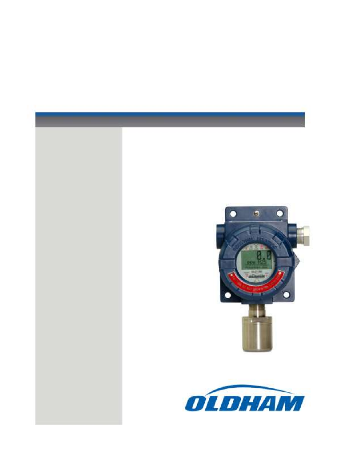
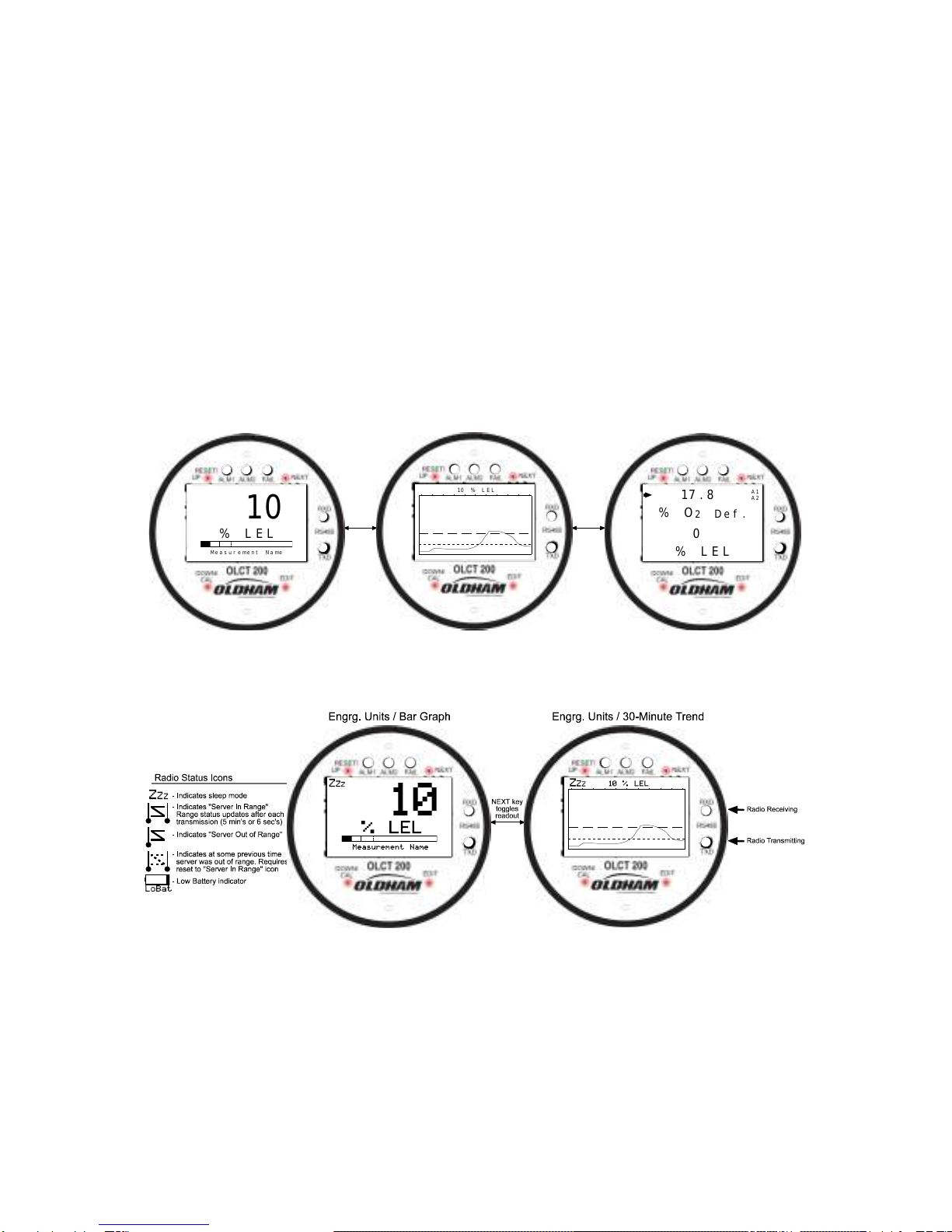
models are only single channel. Monitored values are displayed in their engineering
units as well as graphically as a bar graphs or 30-minute trends (Figure 2.1). Input
types include Electrochemical toxic / oxygen sensors, catalytic bead combustible
sensors, Infrared sensors, as well as Photoionization Detection (PID) sensors.
Sensors supplied by the factory include an 8-wire Smart Sensor interface capable of
configuration data uploads to the OLCT 200. Its advanced microcontroller electronics
and superior graphic LCD operator interface offers enhanced diagnostics and fault
analysis not possible in competing products. The wired OLCT 200 models provides a
standard 4-20 mA output signal for connection to control systems or other alarm
instrumentation. Available options include an Alarm Relay / RS-485-Modbus board, an
Isolated 4-20mA output board, and a HART Communication board. Wireless models
do not accept additional option boards. Non-volatile memory retains all configuration
data during power interruptions. The magnetic, non-intrusive calibration can be easily
performed by one person without opening the enclosure. A standard “real time clock &
calendar” feature allows data logging of calibrations and alarm events for recall to the
LCD readout or over the serial port.
The OLCT 200 wireless models functions on license free 900MHZ or 2.4GHZ wireless
Client / Server networks. Wireless data can be directly transmitted to Oldham WX4,
WX16 and WX64 Controllers. Controllers must be equipped with the matching RF
wireless modem and appropriate antenna to receive the transmissions.
Toxic and oxygen monitors are capable of 2-wire 4-20mA operation (section 2.6.1)
when the alarms / Modbus option and LCD backlight are not required. Catalytic LEL,
Infrared, and PID sensors, or addition of any option board, require the 10-0233 I/O
Power Supply board providing 3-wire 4-20mA operation (section 2.6.3).
Only periodic calibration checks are needed to assure dependable performance.
Operator interface is very intuitive with the LCD displaying data both graphically as bar-
graphs / trends and in engineering units (Figure 2-1). Additional features include:

OLCT 200 User Manual | 10
No potentiometer or jumper settings required. All setup is with menus accessed via the
LCD / magnetic keypad operator interface without opening the enclosure.
Field adjustable alarm levels may be high, low, fault, fail-safe, latching and
acknowledgeable.
New alarms cause front LED’s to flash and become steady after acknowledge.
CAL MODE advises when to apply gas during calibrations
One half hour trend screen shows rate of change of gas exposures
Sensor life bar-graph updates after each SPAN calibration.
Modular design affords efficient installation and plug in sensors allow changing target
gases after installation
New smart sensors are recognized by the OLCT 200 and prompts users to either
upload new configuration data or continue with data from the previous smart sensor.
Missing Sensors trip the “FAIL” alarm.
Sensors are industry proven for fast response and long life.
On screen radio status icons indicate “Server In Range”, “Server Out of Range”, Server
Previously Out of Range” and “Low Battery” conditions.
NEXTUP/
EDITDOWN/CAL
TXD
RXD
RS485
ALM1 ALM2 FAIL
ALM RST
% O2De f .
Dual Channel Split Screen
(Dual Sensor Mode Only)
% L EL
17 . 8
0
A1
A2
NEXTUP/
EDITDOWN/CAL
TXD
RXD
RS485
ALM1 ALM2 FAIL
ALM RST
10 % L E L
Engrg. Units / 30-Minute Trend
NEXTUP/
EDITDOWN/CAL
TXD
RXD
RS485
ALM1 ALM2 FAIL
ALM RST
Me a s u r e me n t Na me
% L EL
10
Engrg. Units / Bar Graph
NEXT key
toggles
readout
NEXT key
toggles
readout
Figure 2-1a: Data Displays –2 Wire and 3 Wire Models
Figure 2-1b: Data Displays –Wireless Models

11
OLCT 200 User Manual | 11
2.2 Ratings and Certifications
Wired Models
CSA certified for Division 1 & 2 hazardous area installations for explosion proof Class 1
Groups B,C,D, and intrinsically safe (OLCT 200/EC 2-wire loops only) Class 1 Groups
A,B,C,D. Also see sections 2.7, 2.7a & 2.8. Designed to meet CSA C22.2 No.152 for
Combustibles Monitors and ISA 92.0.01 Part 1 for Toxic Monitors.
Wireless Models
The enclosure is NRTL certified for Division 1 hazardous area installations for
explosion-proof Class 1 Groups B,C,D (see Figure 2-2c). The OLCT 200 is designed
to meet ISA 92.0.01 Part 1 for Toxic Monitors. The 10-0295 antenna fitting has an RP-
SMA connector and is suitable for Division 2 classified areas. An optional 1000-2193
antenna is also available for Division 1 classified areas. Figure 2-8 shows both
antenna styles.
2.3 Sensor Location
Factors such as air movement, gas density in relation to air, emission sources and
environmental variables affect correct sensor location. Air movement by fans,
prevailing winds and convection should be carefully evaluated to determine if a leak is
more likely to raise gas levels in certain areas within the facility. Vapor density of a gas
determines if it will rise or fall in air when there are no significant currents. Lighter than
air gases should have the monitors mounted 12 –18 inches (30 –45 centimeters)
above the potential gas leak and heavier than air gases should be this distance below.
Even though the OLCT 200 is designed for rugged service, sensors should be
protected from environmental damage from water, snow, shock, vibration and dirt.
2.4 Mounting the Enclosure
The OLCT 200 standard enclosure is a cast aluminum explosion-proof (NEMA 7)
enclosure as shown in Figure 2-2. Figure 2-2a shows dimensions with the dual local
sensor ‘Y’ included. Figure 2-2c shows the wireless model. For wireless models, the
wireless antenna should typically be mounted with “line of sight” access to the
controller’s base station antenna. If a good “line of sight” angle is not possible the
OLCT 200 will usually still function properly at ranges up to 1500 feet but obstructions
should be kept to a minimum.

OLCT 200 User Manual | 12
Figure 2-2a: OLCT 200 Explosion-Proof Housing
Figure 2-2b: OLCT 200 Explosion-Proof Housing with Dual Sensor Head Adaptor
¾" N.P.T. Hub
2 Places
4.61
8.0
Universal
Sensor Head
.25" Dia.
2 Places
5.50
5.3
Dimensions in inches
0010-1200 “Y” Fitting not available
on ATEX compliant model

13
OLCT 200 User Manual | 13
Figure 2-2c: OLCT 200 Wireless Explosion-Proof Housing
Modular design simplifies the installation of the OLCT 200 (Figure 2-3). A top Display
Assembly is mounted with captive thumbscrews and is easily removed to access field-
wiring terminals. An optional 10-0234 Alarms/Modbus board mounts piggyback to the
back of the Display Assembly. Wiring from toxic or oxygen sensors terminates at the
10-0232 Display Assembly along with 2-wire 4-20mA signal wires. This Display
Assembly is the only PC board supplied with toxic / oxygen OLCT 200s not requiring
relays, RS-485 Modbus, HART or LCD backlight. The optional bottom 10-0233 I/O
Power Supply board generates voltages needed for LCD backlight, relays, RS-485
Modbus, HART and Bridge sensor and is required with any of these I/O functions. The
enclosure is equipped with two threaded 3/4 inch NPT conduit fitting outlet and pre-
drilled mounting flanges.
WARNING: Qualified personnel should perform the installation according to applicable
electrical codes, regulations and safety standards. Insure correct cabling and sealing
fitting practices are implemented. Do not aim the sensor pointing upward. Install the
OLCT 200 to a wall or bracket using the predrilled mounting flanges with I.D. 0.25 on
5.5 inch centers (Figure 2-2). If conduit is rigid and able to support the weight of the
OLCT 200, the mounting bolts may be omitted.
CAUTION: The sensor should never be installed pointing upwards.

OLCT 200 User Manual | 14
Figure 2-3a: Outline Drawing –OLCT 200 Wired Models

15
OLCT 200 User Manual | 15
Figure 2-3b: Outline Drawing –OLCT 200 Battery Powered Wireless Models
Figure 2-3c: Outline Drawing –OLCT 200 10-3VDC Powered Wireless Models

OLCT 200 User Manual | 16
2.4.1 10-0322 Magnetic Mounting Option
The 10-0322 Magnetic Mount securely attaches the assembly to solid steel structure
that is at least 6 inches wide.
2.5 System Design Specifications
Supply Voltage:
2 Wire Model
3 Wire Model
10-30VDC
Wireless Model
Battery Powered
Wireless Model
10-30VDC
10-30VDC
10-30VDC
Integral non-
rechargeable 3.6volt
19AH lithium D cell
battery.
Replacement P/N
10-0293.
Power Consumption:
2 Wire Model
3 Wire Model
10-30VDC Wireless
Model
Battery Powered
Wireless Model
25mA max @
24VDC
100mA @ 24VDC
with 0.5watt sensor.
Relays: +40mA per
relay (120mA for
three energized
relays)
RS-485: +20mA
<20mA - “sleep”
mode
60mA –“receive
beacon” mode
Up to 1amp –1
watt “transmit”
mode. Transmit
power can be set
from 10mW –1W.
<2mA - “sleep”
mode
40mA –“receive
beacon” mode
Up to 1amp –1
watt “transmit”
mode. Transmit
power can be set
from 10mW –1W.
Loop Resistance at nominal 24 VDC power:
2 Wire Model
3 Wire Model
10-30VDC Wireless
Model
Battery Powered
Wireless Model
650 ohms
750 ohms
n/a
n/a
Memory:
Non-volatile E2 memory retains configuration values in the event of power outages.

17
OLCT 200 User Manual | 17
Relays (Optional):
Three configurable form C (SPDT) relays rated for 5 amp at 30 VDC or 240 ~VAC
RESISTIVE.
Relay 1 and Relay 2 level alarms are configurable for HIGH or LOW trip, for normally
energized (Failsafe) or normally de-energized and for latching or non-latching.
Relay 3 is always normally energized for failsafe operation so loss of power to the
OLCT 200 will be indicated as a “FAULT” condition.
CAUTION: Relays are rated for RESISTIVE loads. Inductive loads, such contactor
coils or motors may cause contact arcing, which emits RFI into the sensor signals.
Use appropriate snubbers and MOV’s across inductive loads and keep wiring away
from signal wires.
Wireless Specifications:
900MHz Models
2.4GHz Models
Transmit (TX)
Power
30dBm at 1W power. Transmit
power may be set from 10mW
to 1W.
50mW
Receive (RX)
Sensitivity
-100dBm
-90dBm
Radio Frequency
Hopping between 902 –
928MHz.
Hopping between 2.4 –2.5
GHz
2.6 Field Wiring Installation
4-20mA Transmission Range Info:
The distance 4-20 mA signals can travel is dependent upon several factors including
the cable gauge, DC power supply voltage level and impedance of the input of the
receiving device. Assuming a nominal 24 VDC power supply, maximum total loop
resistance is 650 ohms in the 2-wire mode.
Note: WX16 Controllers have 4-20mA input resistance of 100 ohms.
2.6.1 2-Wire 4-20mA Intrinsically Safe & Explosion Proof Installations
OLCT 200’s equipped with 10-0247 sensor heads are NRTL (Nationally Recognized
Testing Lab) certified as suitable for both intrinsically safe and explosion proof
installations. OLCT 200’s equipped with 10-0247IS sensor heads (XP flame arrestor is
not installed to allow monitoring of highly reactive gases such as Hydrogen Chloride or
Ammonia) are NRTL certified as suitable for intrinsically safe installations. All OLCT
200’s are NRTL certified for explosion proof installations as long as the sensor head is
CSA certified as explosion proof. Follow instructions on Installation Drawing # 11-0100
in section 2.6.2 for correct intrinsically safe installations.
Description:
The 2-wire current sinking transmitter is the easiest and most economical to install
since there are only two wires. All of the power needed comes from the current loop

OLCT 200 User Manual | 18
and wire sizes may be smaller. However, only very low power applications are eligible
for such transmitters. The OLCT 200 Display assembly shown in Figure 2-4 consumes
<2.5 mA of quiescent current. Toxic and oxygen electrochemical sensors generate
their own signals and therefore require no additional current. If a 4-20mA output is all
that is required for toxic / oxygen measurements (no LCD backlight, alarms or RS-485)
the OLCT 200 may be used in the 2-wire mode.
CAUTION: It is important to understand the receiver, or controller device must supply
the loop power in 2-wire 4-20mA modes. Be sure the receiver to be used supports this
type of operation.
Instructions:
Unscrew the cover on the OLCT 200 explosion-proof enclosure. Loosen the 2
thumbscrews holding the display assembly in place and remove it. A small sensor
cable is attached with sufficient length to allow access to the back of the display
assembly where 2 position TB1 is located. Route the receiver wires through the
conduit entry and connect to TB1. Steering diodes in the OLCT 200 2-wire 4-20mA
output automatically correct for polarity so positive and negative are interchangeable.
Reassemble the OLCT 200. Follow the procedures and recommendations in the
receiver manual to complete the installation. Be sure the OLCT 200 enclosure and
conduit are properly grounded. Apply loop power by appropriately powering the
receiver device (DCS, PLC, Controller, etc) and the OLCT 200 should function.
Proceed to section-3.
Figure 2-4: 10-0232 Display / 2-Wire 4-20mA Assembly

19
OLCT 200 User Manual | 19
2.6.2 Installation Drawing # 11-0100

OLCT 200 User Manual | 20
2.6.3 3-Wire 4-20mA Mode Installation
CAUTION: OLCT 200’s equipped with the 10-0233 I/O Power Supply board only
operate as 3 or 4-wire 4-20mA transmitters and are not compatible with 2-wire
intrinsically safe installations (see sections 2.6.1 and 2.6.2). Such units should not be
combined with 10-0247IS Sensor Heads without flame arrestors unless the area is
classified as non-hazardous.
OLCT 200’s equipped with the 10-0233 I/O Power Supply and 10-0234 Alarms /
Modbus option are NRTL certified as suitable for Div 1 & 2 Groups B,C,D explosion
proof installations with the 10-0247 or with any sensor head with an equivalent CSA
certification.
Description:
3-wire sourcing transmitters require an additional dedicated 24 VDC wire. The 4-20mA
loop current is then delivered, or sourced, from the transmitter output and the receiver
device must not provide 24 VDC from its input terminal. When the OLCT 200 is
equipped with the bottom 10-0233 I/O Power Supply board shown in Figure 2-5, the 2-
wire 4-20mA output is disabled and one of the 10-0233’s 3-wire outputs must be used.
TB2 terminal 2 is for ECHEM toxic / oxygen 3-wire 4-20mA output signals and TB2
terminal 3 is for LEL 3-wire 4-20mA output signals.
Instructions:
Unscrew the cover on the OLCT 200 explosion-proof enclosure. Loosen the 2
thumbscrews holding the display assembly in place and remove it. A small ribbon
cable is attached with sufficient length to allow access to the I/O PCB mounted in the
bottom of the enclosure (Figure 2-5). Power and signal connections are to TB2 where
24 VDC, Signal and Common wires must be connected. A blocking diode protects the
OLCT 200 if polarity of the power supply is reversed but it will not operate.
Reassemble the OLCT 200. Follow the procedures and recommendations in the
receiver and power supply manuals to complete the installation. Be sure the OLCT
200 enclosure and conduit are properly grounded. Apply power and the OLCT 200
should function. Proceed to section-3.
Table of contents
Other Oldham Transmitter manuals
Popular Transmitter manuals by other brands

RKI Instruments
RKI Instruments 65-2335RK Operator's manual

Emerson
Emerson Rosemount MultiVariable 3051SMV Reference manual

Bell System Practices
Bell System Practices Plant Series Disassembly and Reassembly

HOLATRON SYSTEMS
HOLATRON SYSTEMS SPREAD SPECTRUM 12V Operation & maintenance guide

Eaton
Eaton MTL831C instruction manual

Nautel
Nautel VS300 troubleshooting manual