Oppermann Regelgeräte DDS-AR984 Series User manual

Sensors PG1 | Data sheet No. 13252 | Version 09-2019 | 1| 6
Pressure dierential
transmitter DDS-AR984...
DDS-QR984...
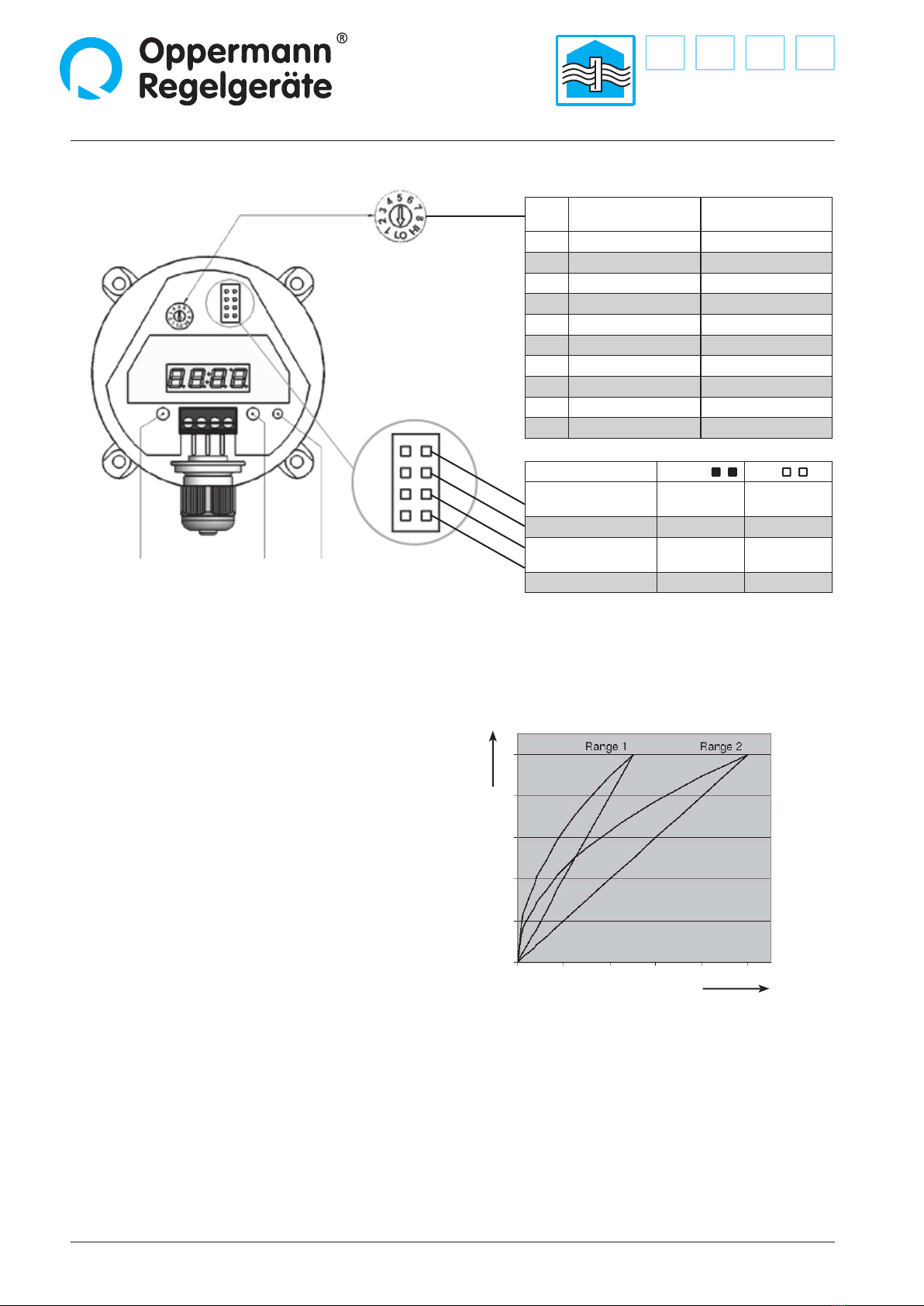
• Automatic zero point setting
• Up to 8 sensor ranges
• Metric cable glands
• Arbitrary installation orientation
• Output can be toggled between square root
extraction/lin.
Technical Data
Compressed medium: Air and non-aggressive media
Power supply: 22 – 30 V AC/DC
Output signal: 0 – 10 V or 4 – 20 mA
Maximum current draw:
• Without display 160 mA
• With LED display 210 mA
Admissible ambient
conditions: -10 - 50 °C, 0 - 95 % RH
(non-condensing)
Long-term stability, type:
n. a.
Load (at 4 – 20 mA): 20 – 500 Ω
Linearity (incl. hysteresis
and reproducibility):
≤ ± 0,5% of full scale, min ± 1 Pa
Uncertainty (total error
excluding long-term and
temperature inuence): ± 1% of full scale, min ± 1 Pa
Switching output (npn): max. 30 V DC/100 mA
Output signal toggle: Linear/square root extraction
Zero setting adjustment: Automatic
Response time settings: Short, 200 ms
Long, 1 s (default state)
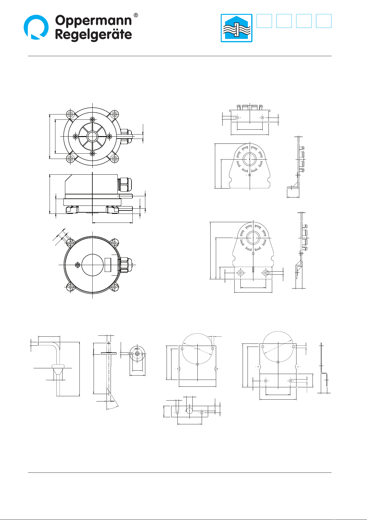
Process ports: 6 mm hose ttings
Electrical connection: Screw terminals for wires
and cores up to 1.5 mm²
Mounting: Screw mounted with
sheetmetal screws
Display, optional: Red LED display, 3.5 characters
Housing material: Switch housing with process port P2,
ABS, light-gray;
Mounting bracket with process port
P1, POM, white
Housing dimensions: approx. Ø 85 mm, H 58 mm
Weight: approx. 150 g
Protection type iaw.
EN60529: IP 54 with protective cover
Cable grommet for
protective cover: M 16 x 1,5 Polyamide threads
Standards / conformity: EN 60770, EN 61326
2011/65/EU (RoHS)
Sensor method: Piezo-resistive pressure transducer
Function
Pressure dierential transmitters of type series DDS 984 are
used to measure dierential, positive, and negative pressure
in gaseous, non-aggressive media. They have up to 8 sensor
pressure ranges and 2 output signals that can be selected
alternatively by swapping a jumper.
The pressure transducer converts the mechanical pressure value
into an electrical sensor signal. The piezo-resistive pressure
transducer integrated into the DDS 984 pressure dierential
transmitter is congured so that the pressure to be read is
applied to a thin mono-silicon membrane. This deects the
membrane. The membrane is equipped with resistors based
on semi-conductor technology. These detect the mechanical
deection and generate an electrical output signal. The arran-
gement of the resistors at the same time results in temperature
response compensation. High-gain process ampliers convert
the signal from the pressure transducer into the output signal.
The electrical output signal changes proportionally to the
applied pressure within the specied error limits.
Possible applications include:
• Building automation, air-conditioning and cleanroom
technology
• Valve and damper control
• Filter, ventilator, and blower monitors
• Airow controls
DDS-AR984…: 2 sensor ranges, automatic zero point setting
DDS-QR984…: 8 sensor ranges, automatic zero point setting

Pressure dierential transmitter DDS-AR984... / DDS-QR984...
2| 6| Sensors PG1 | Data sheet No. 13252 | Version 09-2019
Pressure ranges
Type Sensor range 1 Sensor range 2 Positive pressure
safety
Burst pressure Temperature error
DDS-AR984.5.E.3.K.1 ± 25 Pa - 60 kPa 100 kPa ≤ ± 3% of sensor reading
DDS-AR984.5.X.3.K.1 ± 50 Pa - 60 kPa 100 kPa ≤ ± 2% of sensor reading
DDS-AR984.5.W.3.K.1 ± 100 Pa - 60 kPa 100 kPa ≤ ± 1.5% of sensor reading
DDS-AR984.5.0.3.K.1 0 – 25 Pa 0 – 50 Pa 60 kPa 100 kPa ≤ ± 3% of sensor reading
DDS-AR984.5.1.3.K.1 0 – 50 Pa 0 – 100 Pa 60 kPa 100 kPa ≤ ± 2% of sensor reading
DDS-AR984.5.2.3.K.1 0 – 100 Pa 0 – 250 Pa 60 kPa 100 kPa ≤ ± 2.5% of sensor reading
DDS-AR984.5.3.3.K.1 0 – 250 Pa 0 – 500 Pa 75 kPa 125 kPa ≤ ± 1.5% of sensor reading
DDS-AR984.5.4.3.K.1 0 – 500 Pa 0 – 1,000 Pa 75 kPa 125 kPa ≤ ± 1% of sensor reading
DDS-AR984.5.5.3.K.1 0 – 1 kPa 0 – 2.5 kPa 85 kPa 135 kPa ≤ ± 1 % of sensor reading
DDS-AR984.5.7.3.K.1 0 –5 kPa 0 – 10 kPa 135 kPa 275 kPa ≤ ± 1% of sensor reading
DDS-AR984.5.9.3.K.1 0 – 25 kPa 0 – 50 kPa 200 kPa 400 kPa ≤ ± 1% of sensor reading
DDS-AR984.5.B.3.K.1 0 – 100 kPa 0 – 250 kPa 400 kPa 800 kPa ≤ ± 1% of sensor reading
DDS-AR984.5.….3.K.0 Without display, technical specs as above
Type Switch
position
DDS-QR984.5.4.3.K.1 DDS-QR984.5.5.3.K.1
Pressure range Temperature error Pressure range Temperature error
DDS-QR984.5.4.3.K.1
Positive pressure
safety: 75 kPa
Burst pressure:
125 kPa
DDS-QR984.5.5.3.K.1
Positive pressure
safety: 85 kPa
Burst pressure:
135 kPa
1 0 – 100 Pa ≤ ± 4% of sensor reading ±100 Pa ≤ ± 4% of sensor reading
2 0 – 250 Pa ≤ ± 3.5% of sensor reading 0 – 100 Pa ≤ ± 5% of sensor reading
3 0 – 500 Pa ≤ ± 2% of sensor reading 0 – 200 Pa ≤ ± 4% of sensor reading
4 0 – 1.000 Pa* ≤ ± 1% of sensor reading 0 – 500 Pa ≤ ± 2.5% of sensor reading
5 ± 50 Pa ≤ ± 4% of sensor reading 0 – 1.000 Pa ≤ ± 1.5% of sensor reading
6 ± 100 Pa ≤ ± 3% of sensor reading 0 – 1.500 Pa ≤ ± 1.5% of sensor reading
7 ± 250 Pa ≤ ± 2% of sensor reading 0 – 2.000 Pa ≤ ± 1% of sensor reading
8 ± 500 Pa ≤ ± 1% of sensor reading 0 – 2.500 Pa* ≤ ± 1% of sensor reading
LO Test 0 V/4 mA -Test 0 V/4 mA -
HI Test 10 V/20 mA -Test 10 V/20 mA -
DDS-QR984.….K.0 Without display, technical specs as above
Type name
Type
M16 cable glands
Sensor range: see table„Pressure ranges“
Standard: Unit of measure: Pa
Standard conguration: Output signal: 0 – 10 V or 4 – 20 mA. Output can be toggled between linear/square root extraction With npn switching output.
Display 0 without display
1 with LED display
A 2 sensor ranges, automatic zero point setting
Q 8 sensor ranges, automatic zero point setting
DDS-AR984.5._.3.K.1
DDS-QR984.5.4.3.K.1
DDS-QR984.5.5.3.K.1
* = factory setting

Sensors PG1 | Data sheet No. 13252 | Version 09-2019 | 3| 6
Pressure dierential transmitter DDS-AR984... / DDS-QR984...
Installation
All work (such as installation, electrical connection, startup,
operation, and maintenance) must only be performed by suf-
ciently qualied tradesmen. The respectively applicable local
rules and regulations (e.g. national building codes, electrical/
VDE regulations, etc.) must be observed. Installers and opera-
ting entities are required to suciently familiarize themselves
before startup. Read the product description before operating
the equipment. Verify that the product can be used for the
relevant application without restrictions. We are not liable for
printing errors and changes after printing. Appropriate use
implies compliance with operating and installation instruc-
tions. We are not liable for losses due to inappropriate use.
Unauthorized or inappropriate manipulations or modications
of the device render the operating permit, the product warranty
and warranty claims null and void.
Startup
The 984 pressure dierential transmitter can be operated with
24 V DC or AC. Hoses must not be kinked or damaged while
being connected. Leaking hoses or hose connections cause
malfunctions on the device or will cause incorrect sensor
readings.
Inside hose diameter: 5.5 mm for ideal clamping.
Hose clamps should be used from 25 kPa.
P1 = positive pressure measurements
P2 = negative pressure measurements
P1 & P2 = pressure dierential measurements
The pressure on P1 must always be higher than on P2 to obtain
a correct 0 - 10 V signal. The output signal is connected to
terminals„Out 0 - 10 V“. Note correct polarity. The load must be
selected to avoid exceeding 10 mA output current. As a nal
step, the power supply is connected to the terminals labeled„In
24 V AC/DC.
Installation orientation
The orientation error is eliminated with the self-compensating
piezo sensor cell. The installation orientation is arbitrary.
Automatic zero point setting
Type series DDS AR 984 and DDS QR 984 automatically conduct
a zero point setting in regular, short intervals. This signicantly
improves drift characteristics while also dramatically reducing
inspection and maintenance eort.
Switching output
In addition to the analog output signal, the pressure dierential
transmitter includes an adjustable transistor switching output (npn)
with a maximum switching rating of 35 V DC/100 mA.
Pressure display (optional)
In addition to the output signal, the pressure reading is displayed in
Pascal with a red LED.
Terminal assignment,
3-wire version
Klemmenbelegung
3-Leiter-Ausführung
Load
Load
0…10 V
4...20 mA
4
3
2
4 SA switching output, npn
3 GO ground or GND
2 Y output signal 0 … 10 V/4 ... 20 mA
1 G power supply 24 V AC/DC
1
24 V AC/DC
npn

Pressure dierential transmitter DDS-AR984... / DDS-QR984...
4| 6| Sensors PG1 | Data sheet No. 13252 | Version 09-2019
M = Mode S = Set LED
Pos. pressure range
DDS-QR984.5.4.3.K.1
pressure range
DDS-QR984.5.5.3.K.1
LO Test 0 V / 4 mA Test 0 V / 4 mA
1 0 – 100 Pa ± 100 Pa
2 0 – 250 Pa 0 – 100 Pa
3 0 – 500 Pa 0 – 200 Pa
4 0 – 1,000 Pa 0 – 500 Pa
5 ± 50 Pa 0 – 1,000 Pa
6 ± 100 Pa 0 – 1,500 Pa
7 ± 250 Pa 0 – 2,000 Pa
8 ± 500 Pa 0 – 2,500 Pa
HI Test 10 V / 20 mA Test 10 V / 20 mA
10
8
6
4
2
00 20 40 60 80 100
% P
Sensor range
V
out
Volume ow measurement
A jumper is used to toggle between the measurement metric
„Pressure“ (linear) and„Air volume“ (square root extraction). The
air volume is proportional to the root of the pressure dierential
on both hose connections (pressure dierential method).
Pressure range toggle
Several pressure ranges are available for selection (see table)
for an optimum adjustment of the pressure range. The sensitive
range 1 is selected as the default state. On type series DDS-
AR984, removing the jumper activates the insensitive range 2.
On type series DDS-QR984, one of eight ranges is selected with a
rotating switch.
Adjustable response time
The response time can be adjusted in 2 levels to suppress
brief pressure surges and turbulence, e.g. in the air duct. The
response time is long when the jumper is inserted (default
state). Remove the jumper when the fast response time is
desired.
Output signal toggle
The output signal can be toggled. The default output signal is
0 – 10 V (default setting); it can be switched to 4 – 20 mA by
removing the jumper.
Conguration
Rotating switch for sensor range
(only Type DDS QR984 ...)
Adjusting the switching output
(devices without display)
This functions is used to set the switching output to„intercon-
nected“ for a pressure dened by you. Apply the pressure or
the pressure dierential at which the switching output should
interconnect. Then press button„S“ for 5 sec until the LED blinks
rapidly (= switching point saved). The LED lights up as soon as
the dened pressure is reached or exceeded.
Jumper function Inserted Open
Sensor range
(only series DDS AR 984) Low High
Response time Slow Fast
Operating mode Linear Square root
extraction
Output signal 0 – 10 V 4 – 20 mA

Sensors PG1 | Data sheet No. 13252 | Version 09-2019 | 5| 6
Pressure dierential transmitter DDS-AR984... / DDS-QR984...
Programming (versions with display)

6| 6| Sensors PG1 | Data sheet No. 13252 | Version 09-2019 Specications subject to change.
Pressure dierential transmitter DDS-AR984... / DDS-QR984...
Oppermann Regelgeräte GmbH | Im Spitzhau 1 | 70771 Leinfelden-Echterdingen, Germany
Phone +49 711 72723560 | Fax +49 711 7280527 | info@oppermann-regelgeraete.de |www.oppermann-regelgeraete.de
DDS...984... Mounting bracket 6481
Duct connection-
nipples 6552
Rubber feed-
throughs 6553
Duct connection-
nipples 6551 Mounting bracket 6401 Mounting bracket 6402
Masszeichnungen
100
ø16
ø6
40
50
55
60
ø50
ø4
11
18
7.7
ø10
ø 4.5
40
40
60
70.5
65.5
21.5
ø50
ø4
10
ø5
10
984 mit Kabelverschraubung M16x1,5
Befestigungswinkel 6481
Kanalanschluss für
Climaset®6550/6556
Befestigungswinkel 6402Befestigungswinkel 6401
40
60
7
ø5
46
71
2
19
10
2
6482
60
40
10
19.5
90.5
65.5
ø5
Befestigungswinkel 6482
ø6
18.5
80
ø6.5
60∞
Kanalanschluss für
Climaset®6555/6557
ø 3.4
ø 16
ø 25
ø6
65
50
57.5
21.8
7.5
18
59
ø4.5
8.5
Dimensioned drawing
Mounting bracket 6482
This manual suits for next models
13
Table of contents
Other Oppermann Regelgeräte Transmitter manuals
Popular Transmitter manuals by other brands

MAGMATIC
MAGMATIC MAGRF user manual

Altinex
Altinex MT318-101 user guide

Kramer
Kramer 650T user manual

Canon
Canon Wireless Transmitter WFT-E5A instruction manual

SMAR
SMAR Foundation 302 Series Installation, operation and maintenance manual

Resolution Products
Resolution Products RE203 User and installation instructions