Nailor ELECTRA-FLO G5 User manual

Nailor Industries Inc. reserves the right to change any information concerning product or specification without notice or obligation.
Page 13/21 IOM-ELECTRA-FLO-INST
OPERATION AND MAINTENANCE MANUAL
THERMAL AIRFLOW & TEMPERATURE MEASUREMENT
SYSTEM • ELECTRA-FLO G5 AIRFLOW TRANSMITTER
FOR MODELS AMD-TD-10 & AMD-TD-20
SAFETY INFORMATION
Regarding this manual:
• This manual should be turned over to the end user.
• Before use, read this manual thoroughly to comprehend its
contents.
• The contents of this manual may be changed without prior
notice.
• All rights reserved. No part of this manual may be reproduced
in any form without Nailor’s written permission.
• Nailor makes no warranty of any kind with regard to this
material, including, but not limited to, implied warranties of
merchantability and suitability for a particular purpose.
• All reasonable effort has been made to ensure the accuracy
of the contents of this manual. However, if any errors are
found, please inform Nailor.
•
Nailor assumes no responsibilities for this product except
as stated in the warranty. If the customer or any third party
is harmed by the use of this product, Nailor assumes no
responsibility for any such harm owing to any defects in the
product which were not predictable, or for any indirect damages.
Safety Precautions:
The following general safety precautions must be observed
during all phases of installation, operation, service, and repair
of this product. Failure to comply with these precautions or
with specific warnings given elsewhere in this manual violates
safety standards of design, manufacture, and intended use of
the product. Nailor Industries Inc. assumes no liability for the
customer’s failure to comply with these requirements. If this
product is used in a manner not specified in this manual, the
protection provided by this product may be impaired.
The following messages are used in this manual.
Caution:
Messages identified as "Caution" contain information regarding
potential damage to the product or other ancillary products.
Important Note:
Messages identified as "Important Note" contain information
critical to the proper operation of the product.
Total Flow
Velocity
Temperature
SFPM
F
1335
SCFM3700
70.7
Thermal Airflow Transmitter
ELECTRA-flo G5
UPESC
DNENT

Page 2 3/21 IOM-ELECTRA-FLO-INST
Nailor Industries Inc. reserves the right to change any information concerning product or specification without notice or obligation.
TABLE OF CONTENTS
SECTION 1.0 GENERAL INFORMATION ................................................................................................................................. 3
1.1 Purpose of this Guide ......................................................................................................................................................... 3
1.2 Typical Thermal Airflow Measurement System Installation ................................................................................................ 3
1.3 Standard Features and Specifications ............................................................................................................................ 4, 5
1.4 Checking that You Received Everything ............................................................................................................................ 6
1.5 Working Environment ......................................................................................................................................................... 6
1.6 Serial and Sales Order Number ......................................................................................................................................... 6
SECTION 2.0 INSTALLATION .................................................................................................................................................. 6
2.1 Site Selection ...................................................................................................................................................................... 6
2.2 Transmitter Dimensions ...................................................................................................................................................... 7
2.3 Transmitter Installation ....................................................................................................................................................... 8
2.3.1 ELECTRA-flo G5 Power / Signal Connections ................................................................................................................... 9
2.3.2 ELECTRA-flo G5 Ananlog Outputs & Serial Communication ............................................................................................ 9
SECTION 3.0 OPERATION ....................................................................................................................................................... 10
3.1 Start-up / Operation ...................................................................................................................................................... 10, 11
3.2 User Interface / Device Configuration ................................................................................................................................ 11
3.3 Main Menu ................................................................................................................................................................... 13 - 16
3.4 Network Configuration ................................................................................................................................................ 17 - 27
3.5 Field Characterization ......................................................................................................................................................... 28
3.6 Service Menu .............................................................................................................................................................. 29 - 30
SECTION 4.0 MAINTENANCE, INSPECTIONS, TROUBLESHOOTING ................................................................................. 31
4.1 Maintenance / Inspections .................................................................................................................................................. 31
4.2 Troubleshooting .................................................................................................................................................................. 31

Page 33/21 IOM-ELECTRA-FLO-INST
Nailor Industries Inc. reserves the right to change any information concerning product or specification without notice or obligation.
SECTION 1.0: General Information
Thank you for purchasing the Airflow Measuring Control
Damper with the factory provided Airflow G5 Transmitter. As
our valued customer, Nailor’s commitment to you is to provide
fast, reliable service and assistance while continuing to offer
you the most accurate and reliable products to meet your airflow
measurement and control needs.
1.1 Purpose of this Guide
This manual provides information regarding the installation,
operation and maintenance of the AMD Unit and the provided
Airflow G5 Transmitter. This is NOT, nor is it intended to
be an electrical or HVAC trade manual. This manual is the
basic reference tool for the ELECTRA-flo G5 Transmitter,
including its power
connection and associated outputs. Refer to
supplemental documents for additional information.
1.2 Typical Thermal Dispersion Airflow
Measurement System Installation
Nailor’s Airflow Measuring Damper accurately measures the
average velocity of flowing air by means of thermal dispersion
sensors located in airflow ducts. Temperature is also measured
via these sensors. The Airflow G5 Transmitter can average data
from a maximum of 32 individual flow sensors, and is designed
to measure airflow in a single duct or fan inlet.
Analog outputs and an RS485 interface for BACnet®or
MODBUS®convey data from the Airflow G5 Transmitter to local
controllers or a BMS.
Physical installation details for the Airflow Measuring Dampers
can be found in the Airflow Measuring Damper Installation
Instructions (available at nailor.com).
CONDUIT
CONNECTION
FOR
OUTPUT
SIGNALS
CONDUIT
CONNECTION
FOR
POWER
INPUT
TRANSMITTER TO
PROBE ARRAY CABLE
WITH MINI-DIN
SNAP AND LOCK
CONNECTOR
USER
INTERFACE
KEYPAD
LCD
DISPLAY
Thermal Airflow Transmitter
ELECTRA-flo
UPESC
DNENT
PROBE TO PROBE
CONNECTION IN
DAISY CHAIN
CONFIGURATION
EXTERNALLY MOUNTED PROBES IN HORIZONTAL DUCT
SINGLE CABLE
CONNECTION
FROM PROBE
ARRAY TO
TRANSMITTER
AIRFLOW
Typical Airflow G5 Transmitter and Probe Installation

ELECTRA-flow G5 Transmitter
Performance System
Configuration
Single or dual channel operation
Supports up to 32 individual thermal dispersion airflow sensors
Provides airflow velocity, flow and temperature
Supports multiple airflow measurement system types
Provides three (3) field characterization methods
Operating
Conditions
Ambient Temperature -20°F to 180°F (-29°C to 82°C) (Storage), -20°F to 140°F (-29°C to 60°C) (Operating)
Humidity 0 to 99% RH, non-condensing
Input
Power
24 VAC 20 - 28 VAC, 16 - 90 VA, varies based on # of sensors
24 VDC 20 - 28 VDC, 16 - 50 W, varies based on # of sensors
I/O Signals Two (2) analog outputs, selectable based on configuration
Electronic
Enclosures
Avaiable
Options
• Aluminum, NEMA 1
• Stainless steel, NEMA 4X without viewing window
• Aluminum, NEMA 1 with conduit connection box
• Fiberglass, NEMA 4X with viewing window
Display 2.75" x 2" TFT color LCD
Programming Menu driven user interface via four (4) push buttons
Electrical
Connections
Power Removable terminal block for use with 14 to 18 AWG wire
Communications Removable terminal block for use with 14 to 22 AWG wire
I/O Removable terminal block for use with 14 to 22 AWG wire
Process
Connections
Available
Options
• NEMA 1 enclosure, two (2) mini-DIN connectors XMTR to probes and two (2) 1/2"
conduit openings
• NEMA 4X enclosure, two (2) liquid tight strain relief connectors and two (2) 1/2"
conduit openings
Network Conn. RS485, BACnet® MS/TP or MODBUS® RTU
Approvals
UL 60730
BTL Certified to BACnet standard ISO 16484-5 rev. 1.12
FCC Meets part 15 Subpart B, Class A device requirements
ELECTRA-flo/S5 Thermal Dispersion Probe Array
Performance
Sensor Accuracy Individual sensor accuracy: ±2% of reading from 0 - 5000 FPM
System Accuracy Complete system accuracy: ±3% of reading over published velocity range
Velocity Range
Ducted mounted installations: 0 - 5000 FPM
Station mounted probe arrays: 0 - 5000 FPM (0 - 4000 FPM with straightening cell)
Fan inlet installations: 0 - 10,000 FPM
Sensor
Design
Precision matched, hermetically sealed thermistors with laser trimmed resistive heating element
Dedicated 16 bit A/D processing of each sensor signal
Sensor node consists of two (2) thermistors mounted in a dedicated flow conditioning aperature
Temperature Accuracy ±0.1°F (±0.5°C) over operating range of -20°F to 140°F (-29°C to 60°C)
Sensor
Capacity
Transmitter Maximum of 32 sensors per transmitter, shared between both channels
Probe Maximum of 8 sensors per probe
Page 4 3/21 IOM-ELECTRA-FLO-INST
Nailor Industries Inc. reserves the right to change any information concerning product or specification without notice or obligation.
1.3 Standard Features and Specifications

Page 53/21 IOM-ELECTRA-FLO-INST
Nailor Industries Inc. reserves the right to change any information concerning product or specification without notice or obligation.
ELECTRA-flo/S5 Thermal Dispersion Probe Array - continued
Sensor
Density
Duct & Station
Mounted Three (3) sensor density levels specifiable based on configuration
Fan Inlet Single or dual sensor configuration per inlet available
Probe
Materials of
Construction
Available
Options
• 6063 anodized aluminum, 1 1/8" diameter with NEMA 1 enclosure
• 6063 anodized aluminum, 1 1/8" diameter with NEMA 4 enclosure and IP67
connectors
• 6063 anodized aluminum, 1 1/8" diameter with NEMA 4 enclosure and 1/2" (13)
conduit connections
• 300 series stainless steel, 1 1/8" diameter with NEMA 4X enclosure and 1/2" (13)
conduit connections
Operating
Conditions
Fluid Temperature -20°F to 140°F (-29°C to 60°C)
Humidity 0 to 99% RH, non-condensing
Wiring
Connections
Available
Options
• Mini-DIN, NEMA 1 only
• Watertight - IP67
• Conduit opening with terminal blocks
Duct Mounted
Probe Arrays
Mounting
Options
• Rectangular duct, external or internally mounted
• Rectangular duct, standoff mount
• Circular duct, external or internally mounted
Options • Aluminum honeycomb airflow straightening cell
1.3 Standard Features and Specifications - continued*
NOTE:1 Field characterization required to achieve ±3% system accuracy.
* SPECIFICATIONS subject to change without notice.

Page 6 3/21 IOM-ELECTRA-FLO-INST
Nailor Industries Inc. reserves the right to change any information concerning product or specification without notice or obligation.
1.4 Checking That You Received Everything
Carefully open the Airflow Measuring Damper shipping container(s)
and remove all equipment. Inspect equipment for any damage (if
damaged, contact Nailor and your freight company). Verify that
the following items have been shipped:
• (1) Control Damper in Sleeve with airflow measuring probes
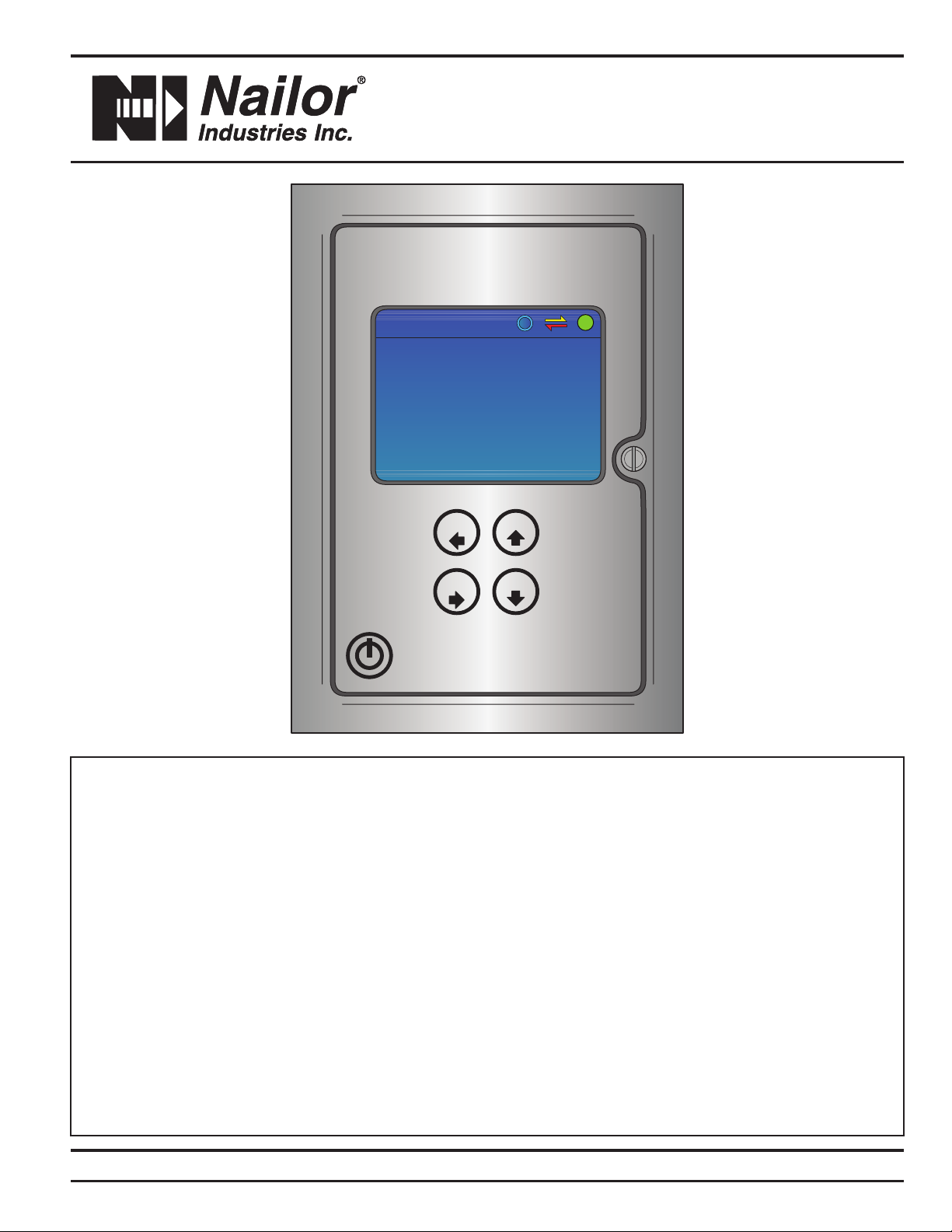
• (1) Airflow G5 Transmitter
• (1) Installation Instructions
Verify that the configuration recorded on the factory set-up sheet
is correct for your application.
Please contact the Nailor Application Engineering Department if
you have questions.
1.5 Working Environment
Airflow G5 transmitter enclosures are designed for use in indoor
installations that are free of condensing moisture. NEMA 4X
enclosures with display windows are designed for use in wet
indoor installations. Do not expose these transmitters to direct
sunlight, temperature extremes or excessive vibration.
The operating ambient air temperature range for both enclosures
is -20°F to 140°F (-29°C to 60°C).
Airflow G5 transmitter enclosures without windows are designed
for indoor or outdoor use. Do not expose these transmitters to
excessive vibration. Whenever possible, avoid exposure to direct
sunlight. The operating ambient air temperature range is -20°F to
140°F (-29°C to 60°C).
1.6 Serial and Sales Order Number
The serial number of your Airflow G5 transmitter is located
outside of the enclosure. The serial number and the sales order
number are a unique identifier for your product. Please have them
available when contacting Nailor for assistance regarding your
product.
The Nailor Airflow Measuring Control Damper should be installed
by experienced HVAC technicians and others with related
knowledge and experience with airflow systems. The installer
should use good trade practices and must adhere to all state and
local building codes.
Each unit is individually calibrated, configured and programmed
using customer specific application data.
Configuration and programming parameters are recorded on
the Factory Set-Up Information Sheet provided with the unit.
Review this information and verify that the set-up is correct for
your application. If any problems or discrepancies are detected,
contact Nailor’s Application Engineering Department prior to
proceeding.
2.1 Site Selection
Careful attention to the site selection for the system components
will help the installers with the initial installation, reduce start-up
problems, and make future maintenance easier. For example,
do not install the unit where it will be difficult for personnel to
perform periodic maintenance. When selecting a site for mounting
the system components, consider the criteria under Section 1.5:
WORKING ENVIRONMENT.
SECTION 2.0 INSTALLATION

Page 73/21 IOM-ELECTRA-FLO-INST
Nailor Industries Inc. reserves the right to change any information concerning product or specification without notice or obligation.
2.2 Transmitter Dimension
10.5"
(267)
10.9"
(277)
6.9"
(175)
7.4"
(188)
7.8"
(198)
10.3"
(262)
4.3"
(109)
10.8"
(274)
8.3" (211)
6.0" (152)
8.5" (216)
6.0" (152)
4.9" (124)
3.5" (89)
6.4"
(163)
2.3"
(58)
NEMA 4X - FIBERGLASS ENCLOSURENEMA 1 ENCLOSURE NEMA 4X - STAINLESS STEEL ENCLOSURE
Thermal Airflow Transmitter
ELECTRA-flo G5
UPESC
DNENT
Thermal Airflow Transmitter
ELECTRA-flo
UPESC
DNENT
3
4
6
6
5
5
2
1
1. Two (2) 0.188 mounting slots.
2. 1/2" conduit field power opening for connection.
3. Two (2) Mini-DIN connectors for probe.
4. 1/2" conduit analog output/network opening for connection.
5. Two (2) 1/2" NPT liquid tight cord grips.
6. Two (2) 1/2" conduit openings with knockouts.

Page 8 3/21 IOM-ELECTRA-FLO-INST
Nailor Industries Inc. reserves the right to change any information concerning product or specification without notice or obligation.
2.3 Transmitter Wiring Connections
1. Graphical LCD for user set-up, commissioning and real-time
data display.
2. User programming and display keys.
3. Micro USB connection location. This can only be used with Air
Monitor firmware update tools. Contact Air Monitor service for
assistance.
4. I/O, serial communication, alarm and power input terminal block
location. Refer to section 2.3.2 for additional information.
5. Termination resisitor / bias switch location. Refer to section 3.4
for additional information.
Thermal Airflow Transmitter
ELECTRA-flo G5
UPESC
DNENT
UPESC
BACnet
D+ D- GSHNOC NC LN
24 V INPUT PWR
J2J1 J3 J4
G
ALARMAO1 / AO2
+ COM / + COM
S1
TERM
BIAS
TERM
BIAS
ON
BACnet
D+ D- GSHNOC NC LN
24 V INPUT PWR
J2J1 J3 J4
G
ALARMAO1 / AO2
+ COM / + COM
S1
TERM
BIAS
J12
J12
J10
U7 U35
RESET
3
5
4
1
2

Page 93/21 IOM-ELECTRA-FLO-INST
Nailor Industries Inc. reserves the right to change any information concerning product or specification without notice or obligation.
2.3.1 G5 Power/Signal Connections
1. Input power requirements:
• 24 VAC (20 - 28 VAC), 16 - 90 VA, varies based on number of
sensors.
• 24 VDC (20 - 28 VDC), 16 - 50 W, varies based on number of
sensors.
2. Alarm can be set for either flow or temperature with upper and
lower limits. Refer to page 16 for more information.
2.3.2 G5 Analog Outputs and Serial Communication
IMPORTANT NOTE
Two (2) analog outputs (4 - 20 mA, 0 - 10 VDC or 0 - 5 VDC) are
available based on configuration. Refer to page 15 for more
information.
BACnet
D+ D- GSHNOC NC LN
24 V INPUT PWR
J2J1 J3 J4
G
ALARMAO1 / AO2
+ COM / + COM
S1
TERM
BIAS
TB - J4
INPUT POWER GROUND (G)
(-) COMMON (N)
(+) 24 V AC/DC (L)
NORMALLY CLOSED CONTACT (NC)
COMMON (C)
NORMALLY OPEN CONTACT (NO)
TB - J3
ALARM
CONNECTION
1
2
BACnet
D+ D- GSHNOC NC LN
24 V INPUT PWR
J2J1 J3 J4
G
ALARMAO1 / AO2
+ COM / + COM
S1
TERM
BIAS
TB - J2
SERIAL
COMMUNICATION SHIELD (SH)
RS485 COMMON (G)
(-) RS485 (D)
(-) AO2 COMMON
(+) AO2
(-) AO1 COMMON
(+) RS485 (D)
(+) AO1
TB - J1
AO OUT 1 & 2

Page 10 3/21 IOM-ELECTRA-FLO-INST
Nailor Industries Inc. reserves the right to change any information concerning product or specification without notice or obligation.
Section 3.0: Installation:
3.1 Start-Up / Operation After power and signal wiring has been verified in accordance
with Section 2.3, activate the 24 VAC / VDC power source.
Start-up
Press the power button located in the lower left corner of the
display. The display will show a bar graph as the program
loads. Once the program is loaded, the transmitter will scan for
sensors and display their status. The normal operating screen
will then be displayed.
Default Display Screen
The display screen provides three lines of process data. The
data shown is field configurable. The default configuration
indicates flow, velocity and temperature.
A field configurable Custom ID is also shown at the bottom of
the screen.
Default Dual Channel Display Screens
The true dual channel version of the Airflow G5 transmitter
has two display screens for process data. Sys1 Flow and Sys2
Flow are provided on the first screen. Sys1 Flow + Sys2 Flow
and Sys1 Flow - Sys2 Flow are provided on the second screen.
The Up arrow is used to toggle between the screens. The field
configurable Custom ID is also shown.
DNENT
Sys1 Flow
Sys1 Flow
Onicon
ACPM
ACPM
0
0
75.6F
74.7F
Sys1 + Sys2
Sys1 - Sys2
Onicon
ACPM
ACPM
0
0
75.6F
74.7F
Total Flow
Velocity
Temperature
Custom ID
SCFM
0
74.7 F
0.0 SFPM
fx
TOTAL SYSTEM SCAN
EXPECTED
DISPLAYED
ESC - LEAVE
2
0
EXPECTED
MISSING
2
0
87654321
161514131211109
2423222120191817
3231302928272625

Page 113/21 IOM-ELECTRA-FLO-INST
Nailor Industries Inc. reserves the right to change any information concerning product or specification without notice or obligation.
3.1 Start-Up / Operation - continued
3.2 User Interface / Device Configuration
Status Icons
The following icons will be displayed at the top of the normal
operating screen whenever the function is active. Refer to the
alert code table on page 30 for additional status codes.
Transmitter communicating normally on the BACnet or MODBUS
Network
Send/Receive arrows flashing indicates the sensor(s) and
transmitter are
Communicating normally
The Airflow G5 transmitter is fully field configurable. The
transmitter is configured using the display and 4-button
membrane keypad. Individual key functions are described
below.
ENT: Enters menu item from main or service menu; moves
cursor to next item below when in sub-menu
ESC: Exits current page or sub-menu item
UP Arrow: Toggles between display pages on dual channel
meters. In the menu mode, it moves cursor "up" through main
and service menus and changes character in sub-menu items.
DOWN Arrow: Moves cursor "down" through main and service
menu and changes character in sub-menu items.
Device configuration options are provided on individual display
pages shown in the main menu table below. A separate service
menu is also provided for diagnostic and product information.
The true dual channel main, service and network configuration
menus are shown on the next page in separate tables.
UP
ESC
DN
ENT

Page 12 3/21 IOM-ELECTRA-FLO-INST
Nailor Industries Inc. reserves the right to change any information concerning product or specification without notice or obligation.
Configuration Menus
Main Menu Selection Description
Density Compensation Select density compensation type for flow output (Actual or Standard CFM)
Select System of Units Select system of units (US or SI)
Select Units of Measure Select velocity and flow units
Flow Configuration Select and configure flow and application parameter (ducted or fan inlet, duct size, fan inlet dia., etc.)
Display Configuration Set brightness and inactivity timeout interval
Analog Output Configuration Configure analog output type, value and averaging filter
Display Averaging Filter Configure display averaging filter
Zero Lockdown Adjust zero lockdown (below a FPM set point, drives display and output to zero)
Alarm/Alert Configuration Configure alarm type, upper and lower limits
Network Configuration Configure BACnet MS/TP or MODBUS RTU network connection
Field Characterization For information on field characterization, please see page 28.
Service Menu Selection Description
Password Configuration Enable/disable and change password
Total System Scan Displays sensor enabled/disabled status
Sensor Enable/Disable Enable or disable system sensors
Sensor Data Scan Displays individual sensor data
Sensor Alert Scan Displays alert codes for each sensor
Custom ID Configure ID (tag) of unit (also device name displayed in BACnet)
Restore Factory Setting Restores display settings to original factory setup
Product Information Displays product information (Serial number, Work Order #, etc.)
Configure Probes vs. Nodes Configure number of probes and sensors per probe
Main Menus System 1 and System 2 (Dual Channel Version Only)
Main Menu Selection Description
Density Compensation Select density compensation type for flow output (Actual or Standard CFM)
Select System of Units Select system of units (US or SI)
Select Units of Measure Select velocity and flow units
Flow Configuration Select and configure flow and application parameter (ducted or fan inlet, duct size, fan inlet dia., etc.)
Display Configuration Set brightness and inactivity timeout interval
Analog Output Configuration Configure analog output type, value and averaging filter
Display Averaging Filter Configure display averaging filter
Zero Lockdown Adjust zero lockdown (below a FPM set point, drives display and output to zero)
Alarm/Alert Configuration Configure alarm type, upper and lower limits
Field Characterization For information on field characterization, please see page 28.

Page 133/21 IOM-ELECTRA-FLO-INST
Nailor Industries Inc. reserves the right to change any information concerning product or specification without notice or obligation.
Service Menu Selection Description
Password Configuration Enable/disable and change password
Total System Scan Displays sensor enabled/disabled status
Sensor Enable/Disable Enable or disable system sensors
Sensor Data Scan Displays individual sensor data
Sensor Alert Scan Displays alert codes for each sensor
Custom ID Configure ID (tag) of unit (also device name displayed in BACnet)
Restore Factory Setting Restores display settings to original factory setup
Product Information Displays product information (Serial number, Work Order #, etc.)
Configure Probes vs. Nodes Configure number of probes and sensors per probe
Service Menu System 1 and System 2 (Dual Channel Version Only)
Network Configuration Description
Network Configuration Configure BACnet MS/TP or MODBUS RTU Network Connection
3.3 MAIN MENU
Density Compensation - Density compensation can be
selected to be actual flow or flow corrected to standard
conditions. The default factory setting is for actual conditions.
The Airflow G5 also allows for inputting the site elevation,
which will add density compensation for average atmospheric
pressure based upon elevation above sea level.
Select System of Units - US or SI units can be selected. US
units will display in CFM and °F. SI units will display in L/s and °C.
IMPORTANT NOTE
When changing between US and SI units, the flow
configuration information will need to be converted and
updated. This is not done by the transmitter. The user must
convert and input.
Select Units of Measure - US and SI velocity and flow units
can be selected.
DENSITY COMPENSATION
CONDITIONS:
SITE ELEVATION:
ENT - ACCEPT ESC - DEL/LEAVE UP/DN - CHANGE
STANDARD
0
SYSTEM OF UNITS
SYSTEM:
ENT - ACCEPT ESC - DEL/LEAVE UP/DN - CHANGE
US
TEMPERATURE
VELOCITY
FLOW:
UNITS OF MEASURE
ENT - ACCEPT ESC - DEL/LEAVE UP/DN - CHANGE
DEG F
SCFMSFPM
SCFM

3.3 MAIN MENU continued
Flow Configuration
The flow configuration menu provides access to modify the
application specific parameters.
IMPORTANT NOTE
All transmitters are factory configured for the intended
application. Changes to the factory configuration should
not be required. A Factory Set-Up Sheet is provided with
each transmitter and provides the details for all factory
configured parameters.
Measurement Type
Indicates whether the probes are installed in a ducted or a
fan inlet application. Ducted applications can be rectangular,
circular or flat oval. For fan inlet applications, the transmitter
can be used with single fan inlets, double fan inlets or multiple
inlet (same size) fan walls. One transmitter accepts up to 32
sensors; typically, there are two sensors per fan inlet, optional
construction uses one sensor per inlet (for fan walls).
Flow Configuration - Ducted
Select the proper duct shape (rectangular, flat oval or circular).
Enter the duct dimensions (inches or millimeters).
Area (cross-sectional duct area) is automatically calculated.
Enter the Max Flow (maximum airflow) in CFM or L/s.
Flow Configuration - Fan Inlet
Select the number of fan inlets being measured (max = 32).
Shape is automatically set to Circular.
Enter the diameter of the fan inlet(s).
Area (cross-sectional duct area) is automatically calculated.
Enter the Max Flow (maximum airflow) in CFM or L/s.
Display Configuration
This screen allows the user to set parameters on various lines
of the display.
There are four display lines on the Airflow G5.
Line 1 - Flow (typical), Velocity or Temperature
Line 2 - Velocity, Flow or None
Line 3 - Temperature, Flow or None
Line 4 - Custom ID or None. This field is settable over BACnet
or through the Service Menu. It is typically used to describe the
transmitter location in the building.
Brightness
Allows the user to set the brightness of the display in real time.
Inactivity Timeout - The time period which holds the display in
menu mode. When the timer expires, the display is returned to
the main display screen showing the process values.
IMPORTANT NOTE
The optional true dual channel version of the Airflow G5
only displays flow.
Page 14 3/21 IOM-ELECTRA-FLO-INST
Nailor Industries Inc. reserves the right to change any information concerning product or specification without notice or obligation.
1.25
FLOW CONFIGURATION
MEAUREMENT TYPE:
SHAPE:
HEIGHT (IN.):
WIDTH (IN.):
AREA (FT2):
MASS FLOW (CFM):
ENT - ACCEPT ESC - LEAVE UP/DN - CHANGE
DUCTED
RECTANGULAR
6.0
30.0
2000.0
1.25
FLOW CONFIGURATION
MEAUREMENT TYPE:
FAN INLETS:
SHAPE:
DIAMETER:
AREA (FT2):
MASS FLOW (CFM):
ENT - ACCEPT ESC - LEAVE UP/DN - CHANGE
FAN INLET
CIRCULAR
6.0
2000.0
60 MIN.
DISPLAY CONFIGURATION
LINE 1:
LINE 1:
LINE 1:
LINE 1:
BRIGHTNESS:
INACTIVITY TIMEOUT:
ENT - ACCEPT ESC - DEL/LEAVE UP/DN - CHANGE
FLOW
TEMPERATURE
ID
100%
VELOCITY

Page 153/21 IOM-ELECTRA-FLO-INST
Nailor Industries Inc. reserves the right to change any information concerning product or specification without notice or obligation.
3.3 MAIN MENU continued
Analog Output Configuration -
The Airflow G5 transmitter is equipped with dual analog outputs.
The Analog Output Configuration menu configures the analog
output type, parameter and filter.
Output Type: 4 - 20 mA DC, 0 - 5 VDC or 0 - 10 VDC
Output 1 and 2: Flow, Velocity or Temperature
Optional True Dual Channel Version
Output 1: Flow, Temperature or SYS1 Flow Add
Output 2: Flow, Temperature or SYS2 Flow Subt
Airflow: Available on connector J1, terminals AO1+ and AO1-
or AO2+ and AO2-. The full scale output is equal to Max Flow as
programmed into the ELECTRA-flo G5 transmitter on the Flow
Configuration menu.
Temperature: Available on connector J1, terminals AO1+ and
AO1- or AO2+ and AO2-. The temperature analog output has a
fixed scale of -40°F to 140°F (-40°C to 60°C).
The filter has a minimum setting of 0 to a maximum setting of
10. To disable the filter, select Off.
IMPORTANT NOTE: Optional True Dual Channel Version
• Sys1 and Sys2 full scale flow values are set in the Sys1
and Sys2 flow configuration menus
• Sys1 Flow Add full scale = Sys1 max flow + Sys2 max flow
• Sys2 Flow Subt full scale = Sys1 flow max
ANALOG OUTPUT CONFIGURATION
OUTPUT TYPE:
OUTPUT 1:
OUTPUT 2:
FILTER:
ENT - ACCEPT ESC - LEAVE UP/DN - CHANGE
4-20 mA
TEMPERATURE
4
FLOW

Page 16 3/21 IOM-ELECTRA-FLO-INST
Nailor Industries Inc. reserves the right to change any information concerning product or specification without notice or obligation.
DISPLAY AVERAGING FILTER
FILTER:
ENT - ACCEPT ESC - DEL/LEAVE UP/DN - CHANGE
10
ZERO LOCKDOWN
LOCKDOWN:
VELOCITY (FPM):
ENT - ACCEPT ESC - LEAVE UP/DN - CHANGE
ON
30
ALARM/ALERT CONFIGURATION
TYPE:
UPPER LIMIT:
LOWER LIMIT:
ENABLE REG. ALERTS:
ENABLE GLOBAL ALERTS:
ENT - ACCEPT ESC - LEAVE UP/DN - CHANGE
NONE
805
ON
ON
865
3.3 MAIN MENU continued
Display Averaging Filter -
The Display Averaging Filter filters the data shown on the
display. It affects all elements of the display. The filter has 1 - 10
settings; 1 is the lightest filter, and 10 represents the heaviest
filter. It also has an Off setting.
Zero Lockdown
Zero Lockdown will drive the displayed flow and velocity, as
well as the associated outputs, to zero when the velocity is
below the set point. As very low air velocities tend to be noisy
and unstable, it may be best for control purposes to raise the
zero lockdown velocity to an appropriate threshold in which the
velocity is steady and reliable.
Alarm/Alarm Configuration
The Alarm/Alert Configuration menu provides access to select
and configure the transmitter alarm and alerts. Alarm type
can be either flow or temperature with Upper and Lower
limits. The transmitter alarm controls an on-board relay (see
the wiring diagram for Normally Open and Normally Closed
configurations). Alerts are messages possibly indicating issues
with sensors or the transmitter
Alarm/Alarm Operation: If the process value (Type) exceeds
the Upper or Lower Limit, the relay will change state from the
default of NO or NC and the Type will change to red. When
the process value recovers to be within the Upper and Lower
Limits, the relay will return to the default state and the Type
will return to black. Limit Units are shown in parentheses.
These units are controlled by the System of Units and the
Units of Measure. If the units are US and the flow is CFH,
CFH will be the units used in Limits.
Alert Operation: Enable Reg. Alerts will turn ON / OFF
Enable Global Alerts will turn ON / OFF

Page 173/21 IOM-ELECTRA-FLO-INST
Nailor Industries Inc. reserves the right to change any information concerning product or specification without notice or obligation.
3.4 NETWORK CONFIGURATION
Network Configuration -
The Airflow G5 is provided with BACnet MS/TP and Modbus
RTU as serial communications protocol options. BACnet is the
default setting. The field configurable serial communications
interface is described on the following pages. Refer to section
2.3 for detailed information on terminal locations and wiring
connections.
Nailor recommends that 3-wire network cables with a separate
shield be used for communications. The interface can be
operated as a 2-wire network with no common, but this
configuration is more susceptible to noise.
Type – Select BACnet MS/TP or Modbus RTU. Modbus
network configuration information begins on page 21.
BACnet MS/TP
Select appropriate Baud Rate, Address, ID and Max Masters.
BACnet MS/TP serial interface connections are made at J2
terminals labeled D+, D-, G and SH.
The positive RS485 connection is made to D+, the negative
connection is made to D-. The 3-wire common connection is
made to G and the shield drain is connected to SH.
CAUTION
Do not connect shield drains to the “G” terminal.
Transceiver: 3-wire, half duplex (1/3 unit load)
Recommended maximum units per segment: 32
Baud rate(s): 9600, 19200, 38400, 57600, 115200 (default
38400) unless specified by end user
MS/TP MAC Address range: 1 – 255
BACnet device instance number range: 0 – 4,194,303
Max master: 1 – 127
End of line termination: Jumper selectable 120 Ohms or
none. Only use on end of line.
Biasing: Jumper selectable 549 Ohms or none. Only one
device on the network should provide biasing.
Flow control: none
The Custom ID menu page provides the Device object
description property over BACnet and on the display. This
property is writable over the network.
BACnet Object Types
BACnet Object Type and number of Objects implemented:
Device: 1
Analog Input - Reports the average temperature or average
flow. Also reports
127
NETWORK CONFIGURATION
TYPE:
BAUD RATE:
ADDRESS:
ID:
MAX. MASTERS:
ENT - ACCEPT ESC - LEAVE UP/DN - CHANGE
BACnet
3
5
38400
J2
BACnet
SHGD-D+
8765

Page 18 3/21 IOM-ELECTRA-FLO-INST
Nailor Industries Inc. reserves the right to change any information concerning product or specification without notice or obligation.
PROTOCOL IMPLEMENTATION STATEMENT
BACnet Protocol Revision: 12
Device Profile (Annex L): BACnet Application Specific Controller
(B-ASC)
MS/TP master (Clause 9), baud rate(s): 9600, 19200, 38400,
56700, 76800, 115200
Device Address Binding: No
BBMD Support Registration By Foreign Devices: No
Character Set Supported: ANSI X3.4
BACnet Interoperability Building Blocks Supported (Annex K):
Data Sharing – Read Property-B (DS-RP-B)
Data Sharing – Read Property Multiple-B (DS-RPM-B)
Data Sharing – Write Property-B (DS-WP-B)
Device Management – Dynamic Device Binding-B (DM-DDB-B)
Device Management – Dynamic Object Binding-B (DM-DOB-B)
Device Management – Device Communication Control-B
(DM-DCC-B)
Device Management – Reinitialize Device-B (DM-RD-B)

Page 193/21 IOM-ELECTRA-FLO-INST
Nailor Industries Inc. reserves the right to change any information concerning product or specification without notice or obligation.
STANDARD OBJECT TYPES SUPPORTED – Device Object
Property Type
Read Only or Writable
Comment
Object Identifier 1 Writable 0 - 4,194,303
Object Name ELECTRA-flo Writable
Alpha-numeric; 16 char limit Linked to "Custom
ID" setting in the Service Menu. Also displays
on the bottom of the LCD display on transmitter.
Object Type Device Read-only
System Status Operational Read-only
Vendor Name Air Monitor Corporation Read-only
Model Name ELECTRA-flo Read-only
Location Default Location Writable
Description Thermal Writable
Protocol Version 1 Read-only
Protocol Revision 9 Read-only
Services Supported
readProperty, readPropertyMultiple,
writeProperty, deviceCommunicationControl,
reinitializedevice, who-has, who-is
Read-only
Object Types Supported
Analog-input, Device Read-only
Object List Varies: (device, 1), (analog input, 0 - X)
where X = 1 + (No. of sensors *2) Read-only
Max. ADPU Length 128 Read-only
Segmentation Supported
No Segmentation Read-only
APDU Time-Out 3000 Read-only
# of APDU Retries 3 Read-only
Max. Master 127 Writable
Device Address Binding
{} Read-only
Database Revision 3 Read-only
Property Default Value Read Only or Writable
Object Identifier Analog Input-0 to Analog Input-X Read-only
Object Name Various Read-only
Object Type Analog-Input Read-only
Present Value REAL Read-only
Status Flags F, F, F, F Read-only
Event State Normal Read-only
Out of Service FALSE Read-only
Description Various Writable
Location Various Writable
Units Various Read-only
STANDARD OBJECT TYPES SUPPORTED – Analog Inputs

Page 20 3/21 IOM-ELECTRA-FLO-INST
Nailor Industries Inc. reserves the right to change any information concerning product or specification without notice or obligation.
The Air Monitor BACnet stack supports the optional property
“DESCRIPTION”.
This is used to indicate the type of information in the object.
For example, for an ELECTRA-flo system, the description will
indicate as “Total Flow” for average flow, or “Avg Temp” for
average temperature. If the object belongs to a sensor in the
system, it will be indicated as “SensorN Velocity” or “SensorN
Flow”, where N is the sensor address. The number of AI objects
is determined by the total number of sensors in the system x
2 with an additional 2 AI objects for system average flow and
system average temperature. For example, an ELECTRA-flo
system with 8 sensors will have a total of 18 AI objects.
Usage of Status Flags
• Each object supports status bits IN_ALARM, FAULT, and
OUT_OF_SERVICE.
• The OOS property indicates the physical input to the object
is not in service.
This will be set by the transmitter if someone intentionally
removes the sensor from the network. If the transmitter
determines there is a problem with any sensor in question,
the OOS bit is set along with the FAULT bit. If the OOS
property is set, data from the physical device will not be
used in any calculation.
• IN_ALARM is set for values which exceed the predetermined
values set in the transmitter memory. This field only affects
the Avg Temp and Avg Flow Analog Input objects
BACnet Engineering Units for Analog Inputs (Defaults)
Flow Rates: Cubic feet per minute, Liters per minute
Temperatures: Degrees Fahrenheit, Degrees Celsius
Analog Input Objects
Object Identifier Function
Analog Input 1 Average Flow Rate
Analog Input 2 Average Temperature
Analog Input (2 + X) Sensor X Velocity
Analog Input (3 + X) Sensor X Temperature
Analog Input Objects (Dual Channel)
Object Identifier Function
Analog Input 0 Average Sys1 Flow
Analog Input 1 Average Sys1 Temperature
Analog Input 2 Average Sys2 Flow
Analog Input 3 Average Sys2 Temperature
Analog Input 4 Sys Flow Plus
Analog Input 5 Sys Flow Minus
Analog Input 6 Sys_1_Velocity_1
Analog Input 7 Sys_1_Temperature_1
The number of Sys_1_Vel & Sys_1_Temp objects will vary
depending on the number of sensors provided with the
channel 1 probe(s).
Analog Input X Sys_2_Velocity_1
Analog Input X + 1 Sys_2_Temperature_1
The number of Sys_2_Vel & Sys_2_Temp objects will vary
depending on the number of sensors provided with the
channel 2 probe(s).
Table of contents
Popular Transmitter manuals by other brands

MG
MG Mini-M M2CA instruction manual

ABB
ABB Navigator 540 instruction manual

Lectrosonics
Lectrosonics SMDB/E01 Series instruction manual

LYNXTechnik
LYNXTechnik Yellobrik OTX 1842 quick reference

Ascent
Ascent POLYTRON ACT AT5000 Quick reference guide

United Electronic Industries
United Electronic Industries DNA 429-512 user manual