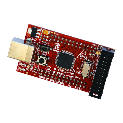
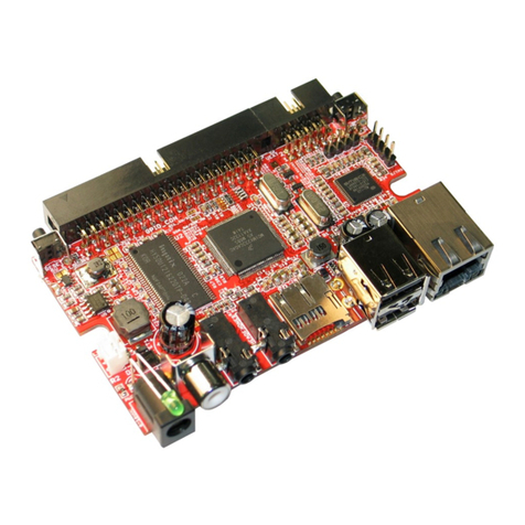
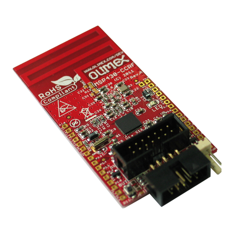
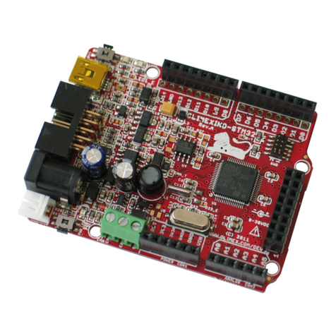
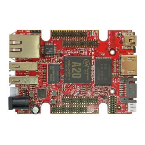
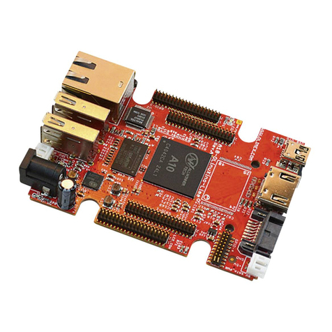
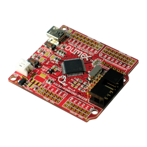
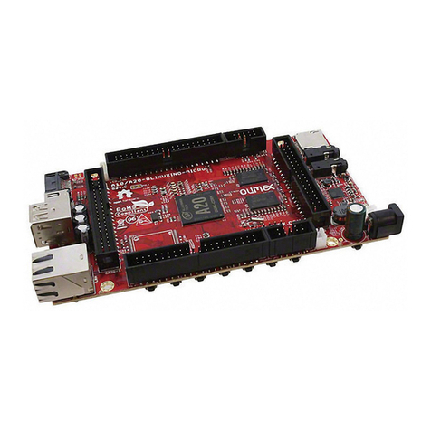
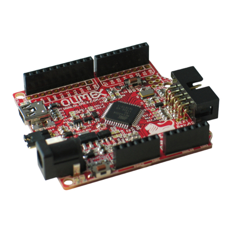
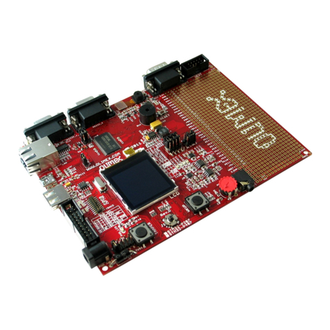
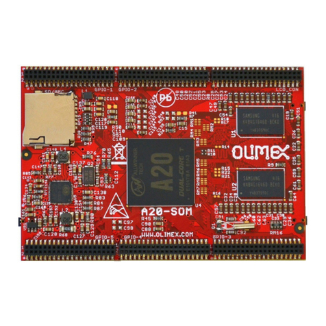
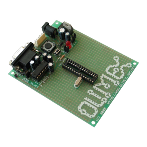
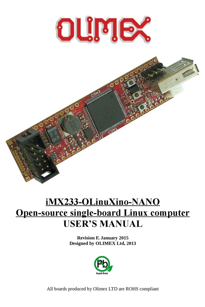
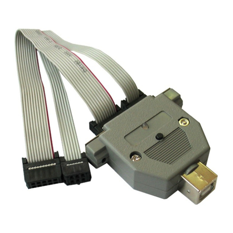
OLIMEX© 01 A13-OLinuXino-MICRO User's Manual
Table of Contents
DISCLAIMER ............................................................................................................. 2
CHAPTER 1: OVERVIEW ........................................................................................ 5
1. Introduction to the ch pter ....................................................................................................... 5
1.1 Fe tures ..................................................................................................................................... 5
1.2 T rget m rket nd purpose of the bo rd .............................................................................. 6
1.3 Bo rd v ri nts .......................................................................................................................... 6
1.4 Org niz tion ............................................................................................................................. 6
CHAPTER 2: SETTING UP THE OLINUXINO BOARD ..................................... 8
2. Introduction to the ch pter ....................................................................................................... 8
2.1 Electrost tic w rning ............................................................................................................... 8
2.2 Requirements ........................................................................................................................... 8
2.3 Powering the bo rd .................................................................................................................. 9
2.4 Prebuilt softw re .................................................................................................................... 10
2.5 Softw re instructions nd v il ble SD c rd im ges ........................................................ 10
CHAPTER 3: A13-OLinuXino-MICRO BOARD DESCRIPTION ..................... 11
3. Introduction to the ch pter ..................................................................................................... 11
3.1 L yout (top view) ................................................................................................................... 11
CHAPTER 4: THE ALLWINNER A13 MICROCONTROLLER ....................... 12
4. Introduction to the ch pter ..................................................................................................... 12
4.1 The microcontroller ............................................................................................................... 12
4.2 Block di gr m ........................................................................................................................ 14
CHAPTER 5: CONTROL CIRCUITY ................................................................... 15
5. Introduction to the ch pter ..................................................................................................... 15
5.1 Reset ........................................................................................................................................ 15
5.2 Clock ....................................................................................................................................... 15
5.3 Power supply circuit .............................................................................................................. 15
CHAPTER 6: CONNECTORS AND PINOUT ...................................................... 16
6. Introduction to the ch pter ..................................................................................................... 16
6.1 Communic tion with the A13 ............................................................................................... 16
6.1.1 USB communication ..................................................................................................................................... 16
6.1.2 UART1 interface ........................................................................................................................................... 16
6.2 SD/MMC slot .......................................................................................................................... 17
6.3 UEXT module ......................................................................................................................... 18
6.4 GPIO-1 (Gener l Purpose Input/Output) 10pin connector ............................................... 19
6.5 GPIO-2 (Gener l Purpose Input/Output) 40pin connector .............................................. 19
6.6 LCD_CON 40pin connector ................................................................................................. 21
6.7 PWR J ck ............................................................................................................................... 22
Page 3 of 30
