CURAEPULIZIA
MANUTENZIONEQUOTIDIANA
ATTENZIONE
Spegnere l’interruttore generale dell’impianto elettrico ogni
qualvolta si effettuano operazioni di pulizia, manutenzione o
sostituzione filtri.
•
Utilizzare un panno umido e soffice per pulire la superfice
della cover.
•
Non usare acqua troppo calda, solventi, benzina o altri
compositi chimici aggressivi, polvere di talco e spazzole:
potrebbero danneggiare la superficie o il colore della cover.
•
Per togliere eventuali macchie, usare acqua tiepida con poco
detergente neutro.
•
Non versare acqua direttamente sul sistema di VMC esulla
cover per pulirla: questo potrebbe danneggiare i componenti
interni o provocare un corto circuito
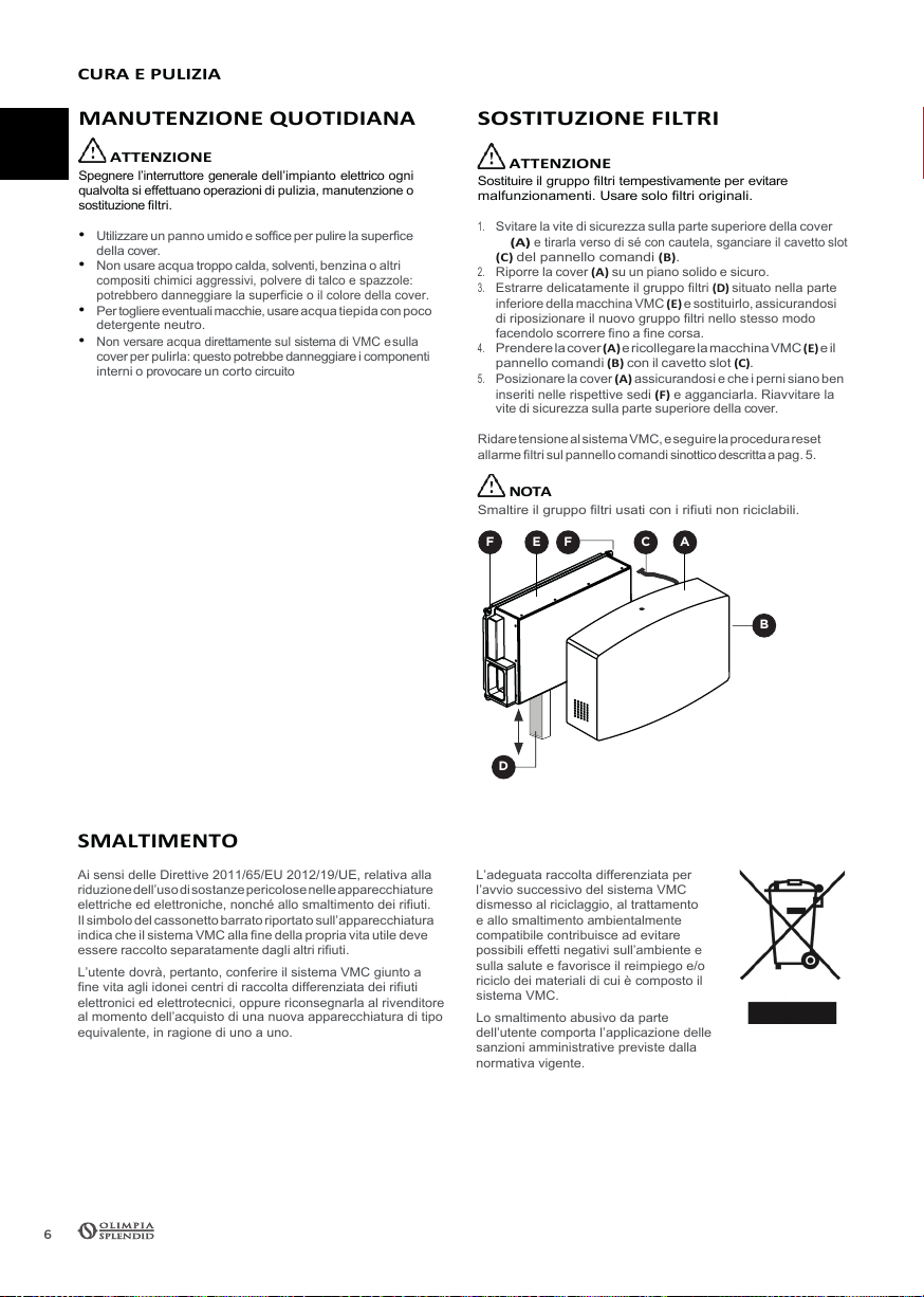
SOSTITUZIONEFILTRI
ATTENZIONE
Sostituire il gruppo filtri tempestivamente per evitare
malfunzionamenti. Usare solo filtri originali.
1.
Svitare la vite di sicurezza sulla parte superiore della cover
(A)
e tirarla verso di sé con cautela, sganciare il cavetto slot
(C)
del pannello comandi (B).
2.
Riporre la cover
(A)
su un piano solido e sicuro.
3.
Estrarre delicatamente il gruppo filtri
(D)
situato nella parte
inferiore della macchina VMC
(E)
e sostituirlo, assicurandosi
di riposizionare il nuovo gruppo filtri nello stesso modo
facendolo scorrere fino a fine corsa.
4.
Prenderelacover
(A)
ericollegarelamacchinaVMC (E)e il
pannello comandi
(B)
con il cavetto slot
(C).
5.
Posizionare la cover
(A)
assicurandosi e che i perni siano ben
inseriti nelle rispettive sedi
(F)
e agganciarla. Riavvitare la
vite di sicurezza sulla parte superiore della cover.
RidaretensionealsistemaVMC,e seguire la procedurareset
allarme filtri sul pannello comandi sinottico descritta a pag. 5.
NOTA
Smaltire il gruppo filtri usati con i rifiuti non riciclabili.
SMALTIMENTO
Ai sensi delle Direttive 2011/65/EU 2012/19/UE, relativa alla
riduzionedell’usodi sostanze pericolosenelleapparecchiature
elettriche ed elettroniche, nonché allo smaltimento dei rifiuti.
Il simbolo del cassonetto barrato riportato sull’apparecchiatura
indica che il sistema VMC alla fine della propria vita utile deve
essere raccolto separatamente dagli altri rifiuti.
L’utente dovrà, pertanto, conferire il sistema VMC giunto a
fine vita agli idonei centri di raccolta differenziata dei rifiuti
elettronici ed elettrotecnici, oppure riconsegnarla al rivenditore
al momento dell’acquisto di una nuova apparecchiatura di tipo
equivalente, in ragione di uno a uno.
L’adeguata raccolta differenziata per
l’avvio successivo del sistema VMC
dismesso al riciclaggio, al trattamento
e allo smaltimento ambientalmente
compatibile contribuisce ad evitare
possibili effetti negativi sull’ambiente e
sulla salute e favorisce il reimpiego e/o
riciclo dei materiali di cui è composto il
sistema VMC.
Lo smaltimento abusivo da parte
dell’utente comporta l’applicazione delle
sanzioni amministrative previste dalla
normativa vigente.
RICEVIMENTODELLAMERCE
Ogni sistema VMC viene controllato accuratamente prima di
essere spedito. All’atto del ricevimento occorre controllare
che il prodotto non abbia subito danni durante il trasporto, in
caso contrario esporre reclamo al trasportatore. Il vettore è
responsabile di eventuali danni derivanti dal trasporto.
I sistemi VMC vengono imballati in scatole di cartone
autoportanti avvolte da film protettivo e a seconda del caso
imballati su pallet e fissati allo stesso tramite regge e film
protettivo.
Dopo aver rimosso il prodotto dall’imballo, assicurarsi della sua
integrità. Non lasciare parti dell’imballo alla portata di bambini o
persone diversamente abili.
MOVIMENTAZIONE
Prima di spostare i sistemi accertarsi che il mezzo utilizzato sia
di portata adeguata.
Per il sollevamento dei pallet servirsi di sollevatore a forche.
In caso di sollevamento a mano il massimo peso consentito è
specificato nella norma 89/391/CEE e successive. Generalmente
è accettabile un peso di Kg 20 al di sotto della spalla ma al di
sopra del livello del suolo, quindi un singolo sistema di VMC per
volta.
STOCCAGGIO
ATTENZIONE
Conservare in luogo riparato, senza eccessiva umidità e non
soggetto a forti sbalzi termici al fine di evitare la formazione di
condensa all’interno dell’unità.
LUOGOD’INSTALLAZIONE
ATTENZIONE
Il sistema di VMC è stato progettato e realizzato per essere
installato e lavorare in ambienti chiusi e al riparo dagli agenti
atmosferici.
Installare il sistema VMC all’interno di edifici con temperatura
ambiente compresa tra 0° e +45°C.
Verificare l’assenza di ostacoli vicino al punto d’ingresso e di
uscita dell’aria.
Per installare i sistemi VMC nei seguenti tipi di ambiente,
contattare il Service:
•
luoghi con atmosfera oleosa o in cui è presente vapore o
fuliggine;
•
ambienti con presenza di salsedine, per esempio sulla costa;
•
luoghi in cui è presente gas solforato, per esempio nelle
vicinanze di fonti di acque termali;
•
luoghi in cui la neve potrebbe ostruire le bocchette esterne;
•
luoghi in cui l’unità si trova a meno di
1
m di distanza da
apparecchi televisivi o radiofonici (l’unità potrebbe causare
interferenze alle immagini oall’audio);
•
altri luoghi che presentano condizioni particolari.
ISTRUZIONIPERL’INSTALLAZIONE
INSTALLAZIONEE
COLLEGAMENTOELETTRICO
ATTENZIONE
I collegamenti elettrici e l’installazione devono essere eseguiti
solo da soggetti in possesso dei requisiti tecnico-professionali di
abilitazioneall’installazione,allatrasformazione,all’ampliamento
e alla manutenzione degli impianti ed in grado di verificare gli
stessi ai fini della sicurezza e della funzionalità.
Prima di collegare l‘apparecchio accertarsi che:
•
la linea di alimentazione dalla rete sia dotata di idoneo
dispositivodidisconnessioneonnipolareconunadistanza
di apertura dei contatti di almeno 3 mm (sezionatori di
linea, integrati alla rete);
•
l’impianto elettrico a cui è collegato il prodotto sia conforme
alle normative vigenti;
•
sia già predisposto il corrugato plastico (a filo muro) per il
passaggio dei cavi elettrici di alimentazione da portare nel
punto tracciato tramite la dima forature, usare filo dalla linea di
tipo H03VV-F/H05VV-F isolato con cavo minimo 2x0,75 mm
2
;
•
i dati sulla targhetta posta sulla macchina VMC (tensione e
frequenza) corrispondano a quelli della rete di distribuzione
elettrica; nel caso di utilizzo alimentatore 220Vac-24V - 50Hz
- IP67 fare riferimento ai dati riportati nell’etichetta;
•
l’alimentazione elettrica sia disinserita.
1.
Svitare la vite di sicurezza sulla parte superiore della cover
(A)
e sganciarla con cautela dalla macchina VMC con piastra
(E)
inserendo un cacciavite nella fessura tra cover e piastra
all’altezza dei perni (F). Fare attenzione a non fare leva sulla
cover stessa.
2.
Sganciare il cavetto slot
(C)
del pannello comandi
(B)
e riporre la cover
(A)
su un piano solido e sicuro.
3.
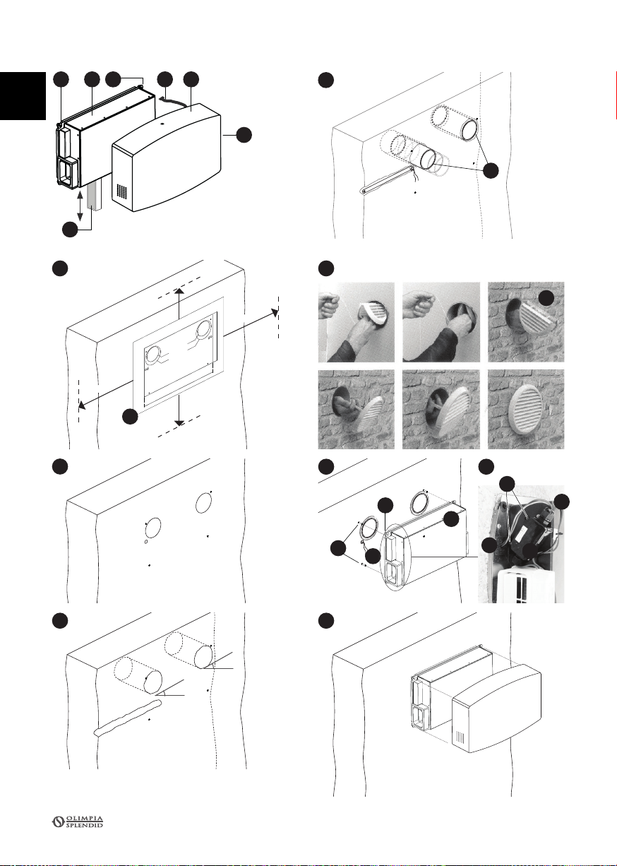
Ritagliareladimaforature(G)doveindicatoeposizionarla
sul muro dove desiderato rispettando gli ingombri minimi
indicati(lateralmente100cm,sopraesotto30cmpertuttii
modelli,daognialtrooggetto/ostacolo/muro),eavendocura
di metterla in bolla tramite una livella (fig.
1).
Tracciare con
una matita i fori di carotaggio, il centro dei fori di fissaggio
piastraeilpuntodiarrivodell’alimentazioneelettrica(fig.2).
4.
EseguireiforidicarotaggioØ100,passantisulmuro,pendenza
negativa esterna 3% (fig.3).
5.
Murare i condotti (H)nei fori di carotaggio tagliandoli a
misura, facendo attenzione a non farli fuoriuscire dal muro
da entrambe le parti ed eseguire le operazioni di rifinitura
muratura se previste (fig.4).
6.
Utilizzare le griglie pieghevoli
(I)
in dotazione, inserire le
suddette griglie nelle tubazioni dal lato interno fino a farle
fuoriuscire sul lato esterno per poi agganciarle tirando verso
di sè il filo (fig.5).
7.
Eseguire i fori per i tasselli di fissaggio
(L)
, da 6 mm forniti
in dotazione (fig. 6).
8.
Passare i fili Fase/Neutro (Marrone/Blu) (N)nel foro di
alimentazionedellapiastra (E), efarlifuoriuscireper una
lunghezza di circa 10 cm.
9.
Fissare la macchina VMC con la piastra
(E)
al muro tramite
le viti in dotazione, facendo attenzione a non pizzicare i cavi
di alimentazione, assicurandosi che la piastra comprima
la guarnizione posteriore. Le boccole viti (M)della
piastra devono essere in battuta con la muratura.
10.
Rimuovere il coperchio della scatola di derivazione (O)svitando
le viti (P), allentare il pressacavo (Q)e passare il filo (N)al
suo interno (facendolo passare dentro il pressacavo come in fig.
6b) collegandolo al morsetto interno. Stringere il pressacavo
avvitandolo e richiudere il coperchio riavvitando le viti.
11.
Prendere la cover (A)e collegare il pannello comandi (B)
sulla cover con il cavetto slot (C).
12.
Posizionare la cover
(A)
assicurandosi e che i perni siano ben
inseriti nelle rispettive sedi
(F)
e agganciarla. Riavvitare la
vite di sicurezza nella parte superiore della cover.
CURAEPULIZIA
MANUTENZIONEQUOTIDIANA
ATTENZIONE
Spegnere l’interruttore generale dell’impianto elettrico ogni
qualvolta si effettuano operazioni di pulizia, manutenzione o
sostituzione filtri.
•
Utilizzare un panno umido e soffice per pulire la superfice
della cover.
•
Non usare acqua troppo calda, solventi, benzina o altri
compositi chimici aggressivi, polvere di talco e spazzole:
potrebbero danneggiare la superficie o il colore della cover.
•
Per togliere eventuali macchie, usare acqua tiepida con poco
detergente neutro.
•
Non versare acqua direttamente sul sistema di VMC esulla
cover per pulirla: questo potrebbe danneggiare i componenti
interni o provocare un corto circuito
SOSTITUZIONEFILTRI
ATTENZIONE
Sostituire il gruppo filtri tempestivamente per evitare
malfunzionamenti. Usare solo filtri originali.
1.
Svitare la vite di sicurezza sulla parte superiore della cover
(A)
e tirarla verso di sé con cautela, sganciare il cavetto slot
(C)
del pannello comandi (B).
2.
Riporre la cover
(A)
su un piano solido e sicuro.
3.
Estrarre delicatamente il gruppo filtri
(D)
situato nella parte
inferiore della macchina VMC
(E)
e sostituirlo, assicurandosi
di riposizionare il nuovo gruppo filtri nello stesso modo
facendolo scorrere fino a fine corsa.
4.
Prenderelacover
(A)
ericollegarelamacchinaVMC (E)e il
pannello comandi
(B)
con il cavetto slot
(C).
5.
Posizionare la cover
(A)
assicurandosi e che i perni siano ben
inseriti nelle rispettive sedi
(F)
e agganciarla. Riavvitare la
vite di sicurezza sulla parte superiore della cover.
RidaretensionealsistemaVMC,e seguire la procedurareset
allarme filtri sul pannello comandi sinottico descritta a pag. 5.
NOTA
Smaltire il gruppo filtri usati con i rifiuti non riciclabili.
SMALTIMENTO
Ai sensi delle Direttive 2011/65/EU 2012/19/UE, relativa alla
riduzionedell’usodi sostanze pericolosenelleapparecchiature
elettriche ed elettroniche, nonché allo smaltimento dei rifiuti.
Il simbolo del cassonetto barrato riportato sull’apparecchiatura
indica che il sistema VMC alla fine della propria vita utile deve
essere raccolto separatamente dagli altri rifiuti.
L’utente dovrà, pertanto, conferire il sistema VMC giunto a
fine vita agli idonei centri di raccolta differenziata dei rifiuti
elettronici ed elettrotecnici, oppure riconsegnarla al rivenditore
al momento dell’acquisto di una nuova apparecchiatura di tipo
equivalente, in ragione di uno a uno.
L’adeguata raccolta differenziata per
l’avvio successivo del sistema VMC
dismesso al riciclaggio, al trattamento
e allo smaltimento ambientalmente
compatibile contribuisce ad evitare
possibili effetti negativi sull’ambiente e
sulla salute e favorisce il reimpiego e/o
riciclo dei materiali di cui è composto il
sistema VMC.
Lo smaltimento abusivo da parte
dell’utente comporta l’applicazione delle
sanzioni amministrative previste dalla
normativa vigente.
Spegnere l’interruttore generale dell’impianto elettrico ogni
qualvolta si effettuano operazioni di pulizia, manutenzione o
sostituzione filtri.
•
Utilizzare un panno umido e soffice per pulire la superfice
della cover.
•
Non usare acqua troppo calda, solventi, benzina o altri
compositi chimici aggressivi, polvere di talco e spazzole:
potrebbero danneggiare la superficie o il colore della cover.
•
Per togliere eventuali macchie, usare acqua tiepida con poco
Non versare acqua direttamente sul sistema di VMC esulla
cover per pulirla: questo potrebbe danneggiare i componenti
interni o provocare un corto circuito
Sostituire il gruppo filtri tempestivamente per evitare
malfunzionamenti. Usare solo filtri originali.
1.
Svitare la vite di sicurezza sulla parte superiore della cover
e tirarla verso di sé con cautela, sganciare il cavetto slot
(C)
del pannello comandi (B).
2.
Riporre la cover
(A)
su un piano solido e sicuro.
3.
Estrarre delicatamente il gruppo filtri
(D)
situato nella parte
inferiore della macchina VMC
(E)
e sostituirlo, assicurandosi
di riposizionare il nuovo gruppo filtri nello stesso modo
facendolo scorrere fino a fine corsa.
4.
Prenderelacover
(A)
ericollegarelamacchinaVMC (E)e il
pannello comandi
(B)
con il cavetto slot
(C).
5.
Posizionare la cover
(A)
assicurandosi e che i perni siano ben
inseriti nelle rispettive sedi
(F)
e agganciarla. Riavvitare la
vite di sicurezza sulla parte superiore della cover.
RidaretensionealsistemaVMC,e seguire la procedurareset
allarme filtri sul pannello comandi sinottico descritta a pag. 5.
Smaltire il gruppo filtri usati con i rifiuti non riciclabili.
SMALTIMENTO
Ai sensi delle Direttive 2011/65/EU 2012/19/UE, relativa alla
riduzionedell’usodi sostanze pericolosenelleapparecchiature
elettriche ed elettroniche, nonché allo smaltimento dei rifiuti.
Il simbolo del cassonetto barrato riportato sull’apparecchiatura
indica che il sistema VMC alla fine della propria vita utile deve
essere raccolto separatamente dagli altri rifiuti.
L’utente dovrà, pertanto, conferire il sistema VMC giunto a
fine vita agli idonei centri di raccolta differenziata dei rifiuti
elettronici ed elettrotecnici, oppure riconsegnarla al rivenditore
al momento dell’acquisto di una nuova apparecchiatura di tipo
equivalente, in ragione di uno a uno.
L’adeguata raccolta differenziata per
l’avvio successivo del sistema VMC
dismesso al riciclaggio, al trattamento
e allo smaltimento ambientalmente
compatibile contribuisce ad evitare
possibili effetti negativi sull’ambiente e
sulla salute e favorisce il reimpiego e/o
riciclo dei materiali di cui è composto il
sistema VMC.
Lo smaltimento abusivo da parte
dell’utente comporta l’applicazione delle
sanzioni amministrative previste dalla
normativa vigente.
CURAEPULIZIA
MANUTENZIONEQUOTIDIANA
ATTENZIONE
Spegnere l’interruttore generale dell’impianto elettrico ogni
qualvolta si effettuano operazioni di pulizia, manutenzione o
sostituzione filtri.
•
Utilizzare un panno umido e soffice per pulire la superfice
della cover.
•
Non usare acqua troppo calda, solventi, benzina o altri
compositi chimici aggressivi, polvere di talco e spazzole:
potrebbero danneggiare la superficie o il colore della cover.
•
Per togliere eventuali macchie, usare acqua tiepida con poco
detergente neutro.
•
Non versare acqua direttamente sul sistema di VMC esulla
cover per pulirla: questo potrebbe danneggiare i componenti
interni o provocare un corto circuito
SOSTITUZIONEFILTRI
ATTENZIONE
Sostituire il gruppo filtri tempestivamente per evitare
malfunzionamenti. Usare solo filtri originali.
1.
Svitare la vite di sicurezza sulla parte superiore della cover
(A)
e tirarla verso di sé con cautela, sganciare il cavetto slot
(C)
del pannello comandi (B).
2.
Riporre la cover
(A)
su un piano solido e sicuro.
3.
Estrarre delicatamente il gruppo filtri
(D)
situato nella parte
inferiore della macchina VMC
(E)
e sostituirlo, assicurandosi
di riposizionare il nuovo gruppo filtri nello stesso modo
facendolo scorrere fino a fine corsa.
4.
Prenderelacover
(A)
ericollegarelamacchinaVMC (E)e il
pannello comandi
(B)
con il cavetto slot
(C).
5.
Posizionare la cover
(A)
assicurandosi e che i perni siano ben
inseriti nelle rispettive sedi
(F)
e agganciarla. Riavvitare la
vite di sicurezza sulla parte superiore della cover.
RidaretensionealsistemaVMC,e seguire la procedurareset
allarme filtri sul pannello comandi sinottico descritta a pag. 5.
NOTA
Smaltire il gruppo filtri usati con i rifiuti non riciclabili.
SMALTIMENTO
Ai sensi delle Direttive 2011/65/EU 2012/19/UE, relativa alla
riduzionedell’usodi sostanze pericolosenelleapparecchiature
elettriche ed elettroniche, nonché allo smaltimento dei rifiuti.
Il simbolo del cassonetto barrato riportato sull’apparecchiatura
indica che il sistema VMC alla fine della propria vita utile deve
essere raccolto separatamente dagli altri rifiuti.
L’utente dovrà, pertanto, conferire il sistema VMC giunto a
fine vita agli idonei centri di raccolta differenziata dei rifiuti
elettronici ed elettrotecnici, oppure riconsegnarla al rivenditore
al momento dell’acquisto di una nuova apparecchiatura di tipo
equivalente, in ragione di uno a uno.
L’adeguata raccolta differenziata per
l’avvio successivo del sistema VMC
dismesso al riciclaggio, al trattamento
e allo smaltimento ambientalmente
compatibile contribuisce ad evitare
possibili effetti negativi sull’ambiente e
sulla salute e favorisce il reimpiego e/o
riciclo dei materiali di cui è composto il
sistema VMC.
Lo smaltimento abusivo da parte
dell’utente comporta l’applicazione delle
sanzioni amministrative previste dalla
normativa vigente.
IT