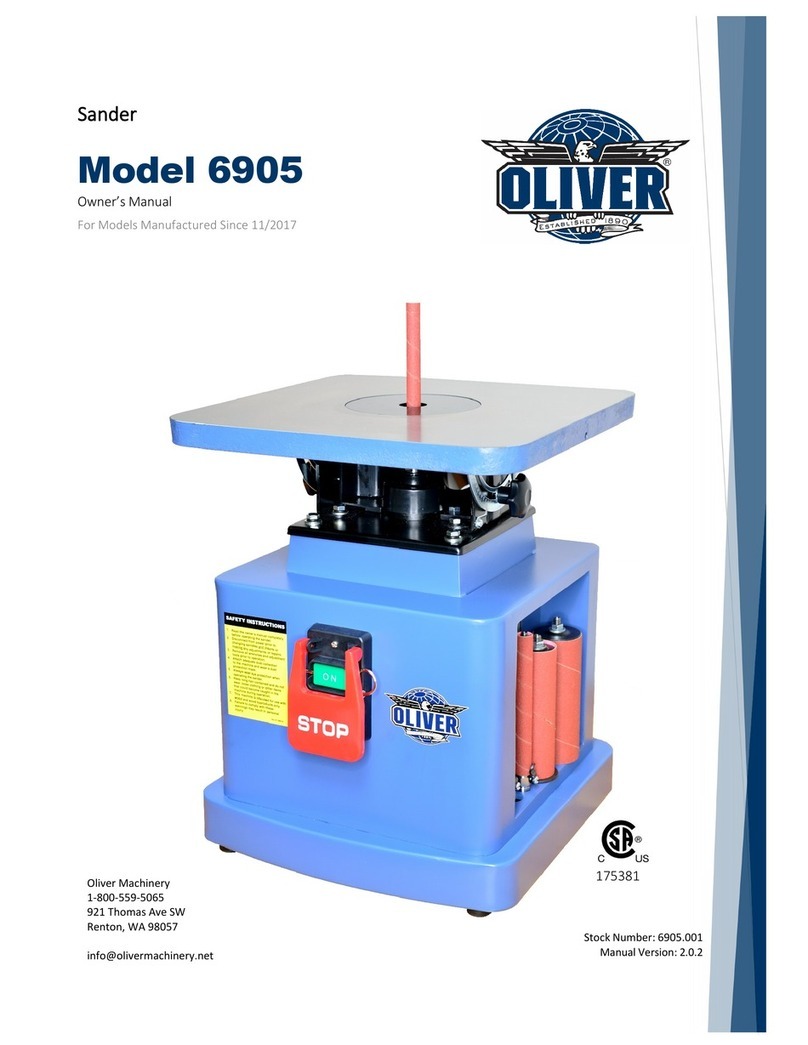
Oliver 6305 User manual

6305 6” x 89” Edge Sander
Owner’s Manual
Oliver Machinery M-6305 10/2014
Seattle, WA Copyright 1999-2014

WARNING
Safety Note: Thoroughly Read Instruction Manual Prior to Operating Sander
1. WEAR eye protection.
2. SUPPORT work piece with backstop or worktable.
3. KEEP GUARDS IN PLACE and in working order.
4. REMOVE ADJUSTNG KEYS AND WRENCHES. Form habit of checking to see that keys and
adjusting wrenches are removed from tool before turning it on.
5. KEEP WORK AREA CLEAN. Cluttered areas and benches invite accidents.
6. DON’T USE IN DANGEROUS ENVIRONMENT. Don’t use power tool in damp or wet locations,
or expose them to rain. Keep work area well lit.
7. KEEP CHILDREN AWAY ALL visitors should be kept safe distance from work area.
8. MAKE WORKSHOP KID PROOF with padlocks, master switches, or by re moving starter keys.
9. DON’T FORCE TOOL. It will do the job better and safer at the rate for which it was designed.
10. USE RIGHT TOOL. Don’t force tool or attachment to do a job for which it was not designed.
11. WEAR PROPER APPAREL. Wear no loose clothing, gloves, neckties, rings, bracelets, or other
jewelry which may get caught in moving parts. Nonslip footwear is recommended. Wear
protective hair covering to contain long hair. Exception: the reference to gloves may be omitted
from the instructions for a grinder.
12. ALWAYS USE SAFETY GLASSES. Also use face or dust mask if cutting operation is dusty.
Everyday eyeglasses only have impact resistant lenses, they are NOT safety glasses.
13. SECURE WORK. Use clamps or a vise to hold work when practical. It’s safer than using your
hand and it frees both hands to operate tool.
14. DON’T OVERREACH. Keep proper footing and balance at all times.
15. MAINTAIN TOOLS WITH CARE. Keep tools sharp and clean for best and safest performance.
Follow instructions for lubricating and changing accessories.
16. DISCONNECT TOOLS before servicing changing accessories, such as blades, bits, cutters,
and the like.
17. REDUCE THE RISK OF UNINTENTIONAL STARTING. Make sure switch is in off position
before plugging in.
18. USE RECOMMENDED ACCESSORIES. Consult the owner’s manual for recommended
accessories. The use of improper accessories may cause risk of injury to persons.
19. NEVER STAND ON TOOL. Serious injury could occur if the tool is tipped or if the cutting tool is
unintentionally contacted.
20. CHECK DAMAGED PARTS. Before further use of the tool, a guard or other part that is
damaged should be carefully checked to determine that it will operate properly and perform its
intended function – check for alignment of moving parts, binding of moving parts, breakage of
parts, mounting, and any other conditions that may affect its operation. A guard or other part
that is damaged should be properly repaired or replaced.
21. DIRECTION OF FEED. Feed work into a blade or cutter against the direction of rotation of the
blade or cutter only.
22. NEVER LEAVE TOOL RUNNING UNATTENDED, TURN POWER OFF. Don’t leave tool until it
comes to a complete stop.

GROUNDING INSTRUCTIONS
1. All grounded, cord-connected tools: in the event of a malfunction or breakdown, grounding
provides a path of least resistance for electric current to reduce the risk of electric shock. This tool is
equipped with an electric cord having an equipment grounding conductor and a grounding plug. The
plug must be plugged into a matching outlet that is properly installed and grounded in accordance with
all local codes and ordinances.
Do not modify the plug provided - if it will not fit the outlet, have the proper outlet installed by a
qualified electrician. Improper connection of the equipment grounding conductor can result in a risk of
electric shock. The conductor with insulation having an outer surface that is green with or without yellow
stripes is the equipment-grounding conductor. If repair or replacement of the electric cold or plug is
necessary, do not connect the equipment-grounding conductor to a live terminal.
Check-with a qualified electrician or service personnel if the grounding instructions are not
completely understood or if in doubt as to whether there tool is properly grounded. Use only 3-wire
extension cords that have 3-prong grounding plugs and 3-pole receptacles that accept the tool’s plug.
Repair or replace damage or worn cord immediately.
2. Grounded, cord-connected tools intended for use on a supply circuit having a nominal rating
less than 150 volts. This tool is intended for use on a circuit that has an outlet that looks like the one
illustrated in Sketch A in Figure the tool has a grounding plug that looks like the plug illustrated in
Sketch A in Figure A temporary adapter, which looks like the adapter illustrated in Sketches B and C,
may be used to connect this plug to a 2-pole receptacle as shown in Sketch B if a properly grounded
outlet is not available. The temporary adapter should be use only until a properly grounded outlet can
be installed by a qualified electrician. The green-colored rigid ear, plug, and the like extending from the
adapter must be connected to a permanent ground such as a properly grounded outlet box.
3. Grounded, cord-connected tools intended for use on a supply circuit having a nominal rating
between 150-250 volts, inclusive: This tool is intended for use on a circuit that has an outlet that looks
like the one illustrated in Sketch D in Figure. The tool has a grounding plug that looks like the plug
illustrated in Sketch D.
Make sure the tool is connected to an outlet having the same configuration as the plug. No
adapter is available or should be used with this tool. If the tool must be reconnected for use on a
different type of electric circuit, the reconnection should be made by qualified service personnel; and
after reconnection, the tool should comply with all local code and ordinances.

3
HEX NUT
WASHER
SPRING WASHER
5/16 Hex. Hd. Scr
A
B
Fig: 1 Fig: 3
The way to change sand band
B
A
Fig: 2 Fig: 4
1. STAND ASSEMBLY : CLAMP PART(A)
AND PART(B) BY HEX NUT , WASER,
SPRING WASER AND SCREW. SEE.FIG.1
2. STAND ASSEMBLY ,SEE FIG.2
1. SANDING TABLE CAN BE ADJUSTED 90°-
180°,SEE FIG.4
2. ADJUST CLAMP HANDLE (B) AT DESIRED TO
CHANGE NEW BELT. SEE FIG.4
3. LOOSEN ANGLE LOCK KNOB(A) TO SET AND
TIGHTEN THE ANGLE.

4
Fig: 5
1.MITER GAUGE (A) CAN BE ADJUSTED 45°-90°
AND CLAMPED BY HEX. HANDLE (B), SEE FIG.5
2.ADJUST MITER GAUGE(A)2.ADJUST MITER
GAUGE(A) TO GET REQUIRED ANGLE GAUGE.
Fig: 6
ADJUST ROLLER TO TARCK BELT SEE FIG. 6
Fig: 6A
ADJUST ROLLER TO TRACK BELT SEE FIG.6
Fig: 7
FOR CONTOUR SANDING SEE FIG. 7
Fig: 7A
FOR CONTOUR SANDING SEE FIG. 7
Fig: 8
1.MOUNT LOCATING PLATE(A) FOR FLAT SANDING.
2.ADJUST KNOB TO CLAMP BRACKET(C) FOR
SECURING JOB. SEE FIG. 8
3.ANGLE LOCK KNOB(A) TO SET ANGLE AT CERTAIN
POSITION.

5

6
A
B
Fig: 9
MAKE SURE DUST HOOD(A) AND HOSE(B) ARE CLAMPED.

PART NO. DESCRIPTION REF. NO. Q'TY
1 BASE 20101001B 1
2 SWITCH W0000000 1
3 SWITCH BOX 10105052n 1
4 PAN HEAD SCREW 3/16"-24UNC*1-1/2" S0030324 3
6 NUT 3/16"-24UNC S0110300 5
7 STRAIN RELIEF S1017W-2 2
8 WORK TABLE BRACKET 20101005 1
9 LOCK NUT 3/8"-24UNC S0120380 1
10 CAM ECCENTRIC 20101007 1
10A NUT 3/8"-16UNC S0110600 1
11 PIN S0310525 1
12 LOCK HANDLE 10102024 1
13 HAND KNOB 10102023 1
14 KEY S0410525 1
15 HEX.HD.SCR. 1/4"-20UNC*1"L S0020416 1
16 WASHER 1/4" S0210404 1
17 TABLE 20101011A 1
17A HEX.HD.SCR. 5/6"-18UNC*5/8"L S0020510 4
18 SPECIAL SCREW 20101065 2
19 NUT M10*P1.5 S0111000M 2
19A SPRING WASHER 3/8" S0210600 2
20 GUIDE BLOCK 20101013 2
21 FENCE 20101014 1
22 KNOB 20101015 3
23 MOTOR ROLLER 20101016 1
24 GUIDE BAR 20102017 1
25 ROLL PIN S0310306 1
26 SOCKET SET SCREW 1/4"-20UNC*1/4"L S0050404 1
27 LOCATING PLATE 10104049 1
28 POINTER 10104050 1
28A LOCATING BLOCK 20102020 1
29 SANDING BELT 6*89 20101021 1
30 MITER GAUGE BODY 10104046 1
31 Rd. Hd. Scr. 5/32"-32UNC*1/2"L S0030108 3
32 HEX. NUT 5/32"-32UNC S0110100 3
33 HAND KNOB 10104045 1
34 SANDING TABLE 20101048 1
34B SANDING TABLE STAND 20101049 1
35 TENSION BAR 20103023 1
36 KNOB 20101039 1
37 PIN S0310640 1

PART NO. DESCRIPTION REF. NO. Q'TY
38 SPRING 20103025 1
39 SPACER 20101055 1
40 HEX. CAP BOLT 5/16"-18UNC*5/16"L S0020510a 1
41 ROLLER ARM 20103050A 1
42 SHAFT 20103051 1
43 ANTI-LOOSE NUT 1/4"-20UNC S0120200 1
43B STEEL BALL 20103029B 1
44 BEARING C1106004 2
45 DRIVEN ROLLER 20103028 1
46 RETAINING RING S0520017 1
47 MICRO-ADJUSTING SCREW 20103029C 1
47A MICRO-INCHING SCREW 20103029A 1
48 INCHING PROTECTION COVER 20201013 1
49 ROUND CROSS HEAD SCREW 3/16"-24UNC*1/4" S0030304 4
50 SPRING WASHER 3/16" S0230300 6
51 BELT REPLACING PLATE 20101031 1
54 SAND CLAMP HANDLE 20101032a 1
55 HEX. HD. SCR. 5/16"-18UNC*1 3/4"L S0020530 1
56 HEX. NUT 5/16"-18UNC S0120201 1
57 TILE SCALE 20101033 1
58 ROUND CROSS HEAD SCREW 3/16"-24UNC*3/4" S0030318 1
59 WIDTH POINTER 10102022 1
60 ROUND CROSS HEAD SCREW 3/16"-24UNC*3/8" S0030304 2
61 MOTOR M000010 1
62 HEX. HD. SCR. 5/16"-18UNC*1 1/4"L S0020520 4
63 FLAT WASHER 5/16" S0210500C 21
64 SPRING WASHER 5/16" S0230506 8
65 HEX. HD. SCREW 5/16"-18UNC S0110500 6
67 MOTOR WIRE L000000M 1
68 POWER WIRE L0000000 1
69 BELT COVER 20101038A 1
69A BELT COVER (SHORT) 20101038a 1
70 LIFTING PLATE 20101002 2
71 KNOB M8*20L 20101024 4
72 BRACKET 20101040 1
73 STAND 30300036 2
74 PARTITION BOARD 30300037 2
77 WASHER 5/16" S0210500 18
78 SPRING WASHER 5/16" S0230506 10
79 HEX. NUT 5/16"-18UNC S0110500 8
80 CAP SCREW 5/16"-18UNC*5/8"L S0020510 10

PART NO. DESCRIPTION REF. NO. Q'TY
81 BELT TENSION DRIVER 20103044 1
82 CROSS HD. SCREW M5*0.8P*12 S0040512M 8
83 TEETH WASHER 3/16" S0220300 8
87 CAP SCREW 5/16"-18UNC*1/4"L S0020520 2
88 RUBBER FEET 10401029 4
89 ROUND HEAD SCREW 5/16"-18UNC*5/8"L S0090512 4
90 HEX. NUT 5/16"-18UNC S0110500 4
91 WASHER 1/4" S0210403 3
92 SPRING WASHER 1/4" S0230400 2
93 HEX. HEAD SCREW M6*1.0P*16 S0020616M 1
94 EXTENSION TABLE 20101051 1
96 SUPPORTING ROD 20101050 1
97 MOUNTING BRACKET 40101016B 1
98 BRACKET 20101052 1
99 CAP SCREW 1/4"-20UNC*5/8"L S0020410 5
100 ANGLE LABLE J0000102 1
101 WARNING LABEL J2000011 1
104 SOCKET SET SCREW 1/4"-20UNC*3/8"L S0050406 2
Other manuals for 6305
1
Table of contents
Other Oliver Sander manuals
Popular Sander manuals by other brands

Bosch
Bosch GET75-6N Operating/safety instructions

Bauer
Bauer 21107E-B Owner's manual & safety instructions

Ingersoll-Rand
Ingersoll-Rand 8448-A1C-EU Operator's manual

General International
General International 15-155 M1 Setup & operation manual

Ryobi
Ryobi PSD101 Operator's manual

Black & Decker
Black & Decker KA300 manual