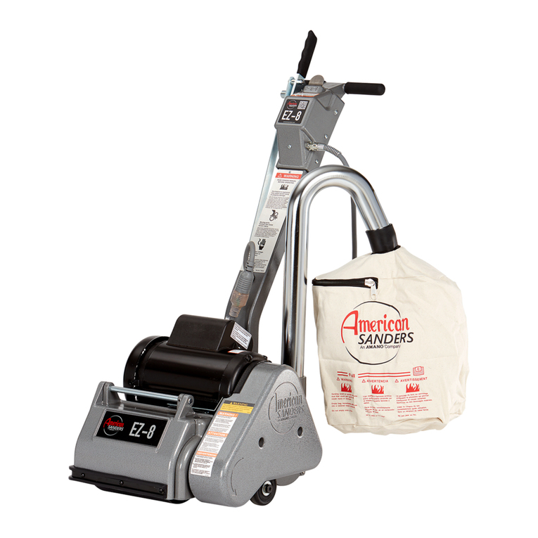
Amano American SANDERS EZ Sand - HDTR User manual

Orbital Sander
EZ-Sand
Operator’s Manual

5
Operator Safety Instructions
DANGER means:Severe bodily injury or death can occur to you or other personnel if the DANGER statements found on this machine
or in this Owner’s Manual are ignored or are not adhered to. Read and observe all DANGER statements found in this
Owner’s Manual and on your machine.
WARNING means:Injury can occur to you or to other personnel if the WARNING statements found on your machine or in this Owner’s
Manual are ignored or are not adhered to. Read and observe all WARNING statements found in this Owner’s Manual
and on your machine.
CAUTION means:Damage can occur to the machine or to other property if the CAUTION statements found on your machine or in this
Owner’s Manual are ignored or are not adhered to. Read and observe all CAUTION statements found in this Owner’s
Manual and on your machine.
DANGER: Failure to read the Owner’s Manual prior to operating or servicing your Clarke American Sanders machine could result in
injury to you or to other personnel; damage to the machine or to other property could occur as well. You must have training
in the operation of this machine before using it. If you or your operator(s) cannot read this manual have it explained fully
before attempting to operate this machine.
DANGER: Sanding/nishingwoodoorscancreateanexplosiveorcombustibleenvironment.Donotoperatethismachinearound
solvents,thinners,alcohol,fuels,oornishes,wooddustoranyotherammablematerials.Cigarettelighters,pilotlights,
electrical sparks and all other sources of ignition should be extinguished or avoided. Keep work area well ventilated.
DANGER: Electrocution could occur if the machine is being serviced while the machine is connected to a power source. Disconnect the
power supply before servicing.
DANGER: Electrocutionorrecouldoccurifthemachineisbeingoperatedwithadamagedpowercord.Keepthepowercordclearofthe
pad. Always lift the cord over the machine. Do not move the machine by the power cord.
DANGER: To avoid injury keep hands, feet, and loose clothing away from all moving parts on the machine. Disconnect the power cord
before replacing the pad, changing the abrasive, or when servicing. Do not operate the machine unless all guards are in place.
Never leave the machine unattended while connected to a power source.
DANGER: Dustgeneratedfromsandingwoodoorscanspontaneouslyigniteorexplode.Promptlydisposeofanysandingdustinametal
containerclearofanycombustibles.Donotdisposeinare.
WARNING: This sander is not to be used on pressure treated wood. Some pressure treated woods contain arsenic and sanding pressure
treated wood produces hazardous dust. Inhaling hazardous dust from pressure treated wood can cause serious injury or death.
Sanding pressure treated wood decks or uneven surfaces can damage the sander which is not covered under warranty or
damage waiver.
WARNING: This machine should be grounded while in use to protect the operator from electric shock. This machine is provided with a
three-conductorcordandathree-contactgroundingtypeattachmentplugtotthepropergroundingtypereceptacle.Thegreen
(or green and yellow) conductor in the cord is the grounding wire. Never connect this wire to anything other than the grounding
pin of the attachment plug.
WARNING: Shock hazard. Do not use the machine if it has been rained on or sprayed with water.
WARNING: Injury can occur if protective clothing or equipment is not used while sanding. Always wear safety goggles, protective clothing,
and dust mask while sanding.
WARNING: Any alterations of modications of this machine could result in damage to the machine or injury to the operator or other
bystanders.Alterationsormodicationsnotauthorizedbythemanufacturervoidsanyandallwarrantiesandliabilities.
***THIS MACHINE IS INTENDED FOR COMMERCIAL USE ONLY***
English - EN Section - A

Introduction & Machine Specications
6
Model EZ Sand - HDTR
Code Number 07163A
Voltage Frequency 115V / 60Hz
Amperage (A) 12
Motors (3) 1/3 hp each
Pad Size (3) 7” O.D. each
Power Cable 40 Ft. 12/3 Ga. Gray Rubber Jacketed
Orbits Per Minute 5000 Each Motor
Orbit Diameter 1/4 inch
Shipping Weight 110 lbs
Noise (dBA) 74
Vibration (m/s/s) 16
Section - A English - EN

To transport the machine, follow this procedure:
1. Unplug machine from wall outlet and wrap cord.
2. Raise and lock the handle to the vertical and upright
position. To lock the handle, unhook the knurled
collar by raising and twisting it (See Figure 1), and
then allow it to slide into the black cast iron weight
(See Figure 1A).
3. Unlock the three levers that attach the black cast iron
weight to the base machine by lifting up.
4. Unplug the interconnect cord from the base machine.
Now the handle can be lifted separately and placed in
the cargo hold.
5. The base machine can be lifted by grasping both the
front lift handle and underneath the axle area (See
Figure 2).
WARNING:
The machine is heavy (67 lbs./34kg). The handle
weight is 35 lbs./16 kg. To avoid injury or damage
to the machine use a rm grip and proper lifting
technique. Get assistance if necessary.
6. Always transport the machine with sandpaper
attached to the drivers. Damage to the grip face will
occur if sandpaper is not in place during transport or
storage.
7. Secure machine to prevent movement in cargo area.
7
Machine Transportation
Figure 2
Figure 1A
Figure 1
English - EN Section - A

To prepare the machine for use follow this procedure:
1. Familiarize yourself with the machine. Read all
danger, warning, and caution statements and the
Operator’s and Parts Manual before operating the
machine. If you or the operator are unable to read
English, have this manual fully explained before
attempting to operate this machine.
2. Attach the handle to the base machine by following
these instructions:
A. The handle label should be pointing towards the
front of the machine and the black iron casting
should drop down into the top of the base machine
securely.
B. Snap the three latches down to the base machine.
The hooks on the latches should slip over the
keepers that are attached to the base machine.
The latches should require a slight push to snap
them into place (See Figure 3).
C. Plug the cord at the bottom of the handle into cord
coming out of the machine base and slightly twist
to lock it in place (See Figure 3A).
3. Install or replace sandpaper. The sandpaper should
be replaced if it is ripped, torn or the hook material is
too worn to allow attachment of sandpaper. To install
or replace the sandpaper follow these instructions:
A. Make sure the power cord is not connected to a
wall outlet or any power source.
B. Lock handle in the upright position.
C. Tilt the machine back until it fully rests on the
handle.
D. While kneeling and facing the bottom of the
machine, remove the existing sandpaper (See
Figure 4).
E. Press the new sandpaper against the grip face until
the hooks in the driver have set into the sandpaper
(See Figure 4A).
F. Return machine to the upright position.
CAUTION:
Damage to the grip face on the driver will occur if the
machine is operated without sandpaper installed.
CAUTION:
Always store the machine with sandpaper installed on
all of the drivers to prevent damage to the grip face.
WARNING:
Never put yourself or let others be in a position to get
injured if the machine should tip or fall while replacing
the pad or changing abrasive.
8
Machine Set-Up
Figure 3
Figure 3A
Figure 4
Figure 4A
Section - A English - EN

This sanding machine is designed to be operated with a
remote vacuum dust collection system or with the included
dust bag.
Preparing Remote Vacuum Dust Collection Systems
To prepare the machine for remote vacuum dust
collection systems that have a 2” hose end, install 2”
hose end (Figure 5 - “A”) directly over the exhaust tube
(Figure 5 - “B”).
To prepare the machine for remote vacuum dust
collection systems that have a 1 ½” hose end, follow this
procedure:
1. Install the 2” x 1½” hose end adaptor (Part No.
30563A) (Figure 5 - “C”) over the exhaust tube (Figure
5 - “B”).
2. Insert 1 ½” hose end (Figure 5 - “D”) into the adaptor
(Figure 5 - “C”).
NOTE: Start the remote vacuum collection system
before operation.
Preparing to use the included dust bag
To prepare the machine for use with the included dust
bag (Part No: 53544C), follow this procedure:
1. Install the dust bag by pressing the end onto the
exhaust tube until the ring locks into the groove
(Figure 6).
2. To remove the dust bag from the exhaust tube, pry
up the end of the bag opening to partially release the
internal rib from the groove, then pull.
3. To empty the dust bag, unzip the disposal ap and
force contents out by inverting the bag.
NOTE: For best results, empty frequently. Follow all
warnings posted in this manual and on the dust bag.
WARNING:
Never leave sanding dust unattended!
DANGER:
Dust generated from sanding wood oors can
spontaneously ignite or explode. Promptly
dispose of any sanding dust in a metal container
clear of any combustibles. Do not dispose in a
re.
9
Dust Collection
Figure 5
A
D
C
B
1.5” Hose From
Vacuum System
(Not Included)
2” Hose From
Vacuum System
(Not Included)
Exhaust Tube (Part # 30563A)
2” Tube x 1.5”
Hose Adapter
(Not Included)
Figure 6
Install the dust bag by
pressing the end onto the
exhaust tube until the ring
locks into the grove.
English - EN Section - A

Follow this procedure for sanding oors:
1. Move machine to work location. Decide the best
approach to sanding the desired area. When sanding
the area, work so that you are moving away from the
power supply. This will help to avoid entanglement
with the power cord and reduce the need to move the
power cord as frequently.
2. Install the sandpaper. Use the same procedure
outlined in MACHINE SETUP to install the sandpaper.
The sandpaper uses a hook and loop system which is
identical to how the pads attach to the drivers. Center
the sandpaper over the driver and press it against the
driver until the grip face has set into the sandpaper.
WARNING:
Injury can occur if the machine is connected to
a power source while installing the sandpaper.
Disconnect the machine before installing the
sandpaper.
3. Connect the machine to an appropriately fused and
grounded circuit.
4. While holding the handle, reach down and slide the
knurled locking collar up the handle tube and hook
it to the pin in the tube by rotating it (See Figure 7).
Lower the handle down to a comfortable position.
5. To run the machine, push the interlock button (See
Figure 8 - “1”), and apply pressure to the levers (See
Figure 8 - “2”). To stop the machine, release the
levers (See Figure 8 - “2”).
CAUTION:
To prevent damage to the ooring and to reduce
swirling, keep the machine in motion while the motor
is running.
NOTE: For sanding cuts and sandpaper, see page A9
10
Operating Instructions
Figure 8
1
2
2
Figure 7
Section - A English - EN

11
Troubleshooting
Problem Possible Cause Solution
No Power. Check power supply and connection.
Interlock not depressed. Depress Interlock before activating control lever.
Defective switch / Bad Connection Contact an authorized American Sander Technology Dealer.
Low voltage from excessive length or
undersized extension cord. Use a 14 Ga extension cord, not to exceed 50’ length.
Defective start switch. Contact an authorized American Sander Technology Dealer.
Defective motor. Contact an authorized American Sander Technology Dealer.
Eliminate extension cord. Locate power source closer to work site.
Have voltage checked by a qualified electrician.
Bad Connection. Contact an authorized American Sander Technology Dealer.
Defective Motor. Contact an authorized American Sander Technology Dealer.
Handle feels loosely connected to
machine base. The latches have loosened up. To tighten latches, loosen the lock nut, screw in the latch hook and then
tighten the lock nut.
Low Voltage.
Motor will not start.
Motor fails to start / runs sluggish.
Fuse / Circuit Breaker repeatedly
trips.
Sanding Cuts and Sandpaper
Initial Cut
The purpose of the initial cut is to remove old nish and gross imperfections on the oor surface. Use a course (20-
36 grit) grain abrasive.
Final Cuts
The purpose of a nishing cut is to remove the scratches produced during the initial cut. Use a ne (60-80 grit) grain
abrasive.
If the surface remains rough after a nishing cut, it may be necessary to use an even ner grain of abrasive (80-
100grit). Care should be taken in selecting the grit size of the abrasive. A very ne grain will close the pores on a
wood oor making admission of a stain difcult.
Note: If glazing or burning should occur the abrasive has dulled and must be replaced.
English - EN Section - A
Taylor Rental Center
1560 Hwy 1 S/MLK Blvd.
Greenville, MS 38701
662-335-3535 Phone
662-335-3533 Fax
www.taylorrentalgreenville.com
Table of contents
Other Amano Sander manuals

Amano
Amano American Sanders Epoch HD User manual
Amano
Amano American SANDERS FloorCrafter User manual

Amano
Amano American Sanders OBS-18DC User manual

Amano
Amano American Sanders 3DS User manual

Amano
Amano American Sanders American 12 User manual

Amano
Amano American SANDERS FloorCrafter User manual
Amano
Amano American Sanders American 8 User manual
Amano
Amano American Sanders OSB-18 User manual

Amano
Amano Pioneer Eclipse 225FP16TR User manual

Amano
Amano Pioneer Eclipse PE225FP User manual
