Oliver 6320 User manual


READ AND UNDERSTAND ALL INSTRUCTIONS IN THIS MANUAL BEFORE
ATTEMPTING TO ASSEMBLE OR OPERATE THE MACHINE.
FOLLOW THE INSTRUCTIONS AND THINK SAFETY!
THE OWNER OF THIS MACHINE IS SOLELY RESPONSIBLE FOR THE SAFETY OF ANYONE USING
THIS MACHINE. SUCH RESPONSIBILITY INCLUDES BUT NOT LIMITED TO THE FOLLOWING:
•PROPER ASSEMBLY, OPERATION, INSPECTION, MAINTENANCE, AND RELOCATION OF
THE MACHINE.
•PROPER TRAINING FOR THE OPERATORS AND ENSURES THIS MANUAL IS AVAILABLE AT
ALL TIMES.
•USAGE AUTHORIZATION.
•USAGE OF SAFETY AND PROTECTION DEVICES.
OLIVER MACHINERY DISCLAIMS ANY LIABILITY FOR MACHINES THAT HAVE BEEN ALTERED OR
ABUSED. OLIVER MACHINERY RESERVES THE RIGHT TO EFFECT AT ANY TIME, WITHOUT PRIOR
NOTICE, THOSE ALTERATIONS TO PARTS, FITTINGS, AND ACCESSORY EQUIPMENT WHICH THEY
MAY DEEM NECESSARY FOR ANY REASON WHATSOEVER.
** SAVE THIS MANUAL FOR FUTURE REFERENCE. **
PROP 65 NOTICE
WARNING: Drilling, sawing, sanding, or machining wood products can expose you to wood dust
and/or other chemicals that are known to the State of California to cause cancer, birth defects,
or other reproductive harm.
Some examples of these chemicals are:
•Lead from lead-based paints.
•Crystalline silica from bricks, cement, and other masonry products.
•Arsenic and chromium from chemically treated lumber.
Avoid inhaling wood dust and other harmful chemicals. Use a dust mask and/or other safety
devices for personal protection.
For more information, go to http://www.P65Warnings.ca.gov/wood

Table of Contents
Introduction············································· 5
Specifications ·········································· 6
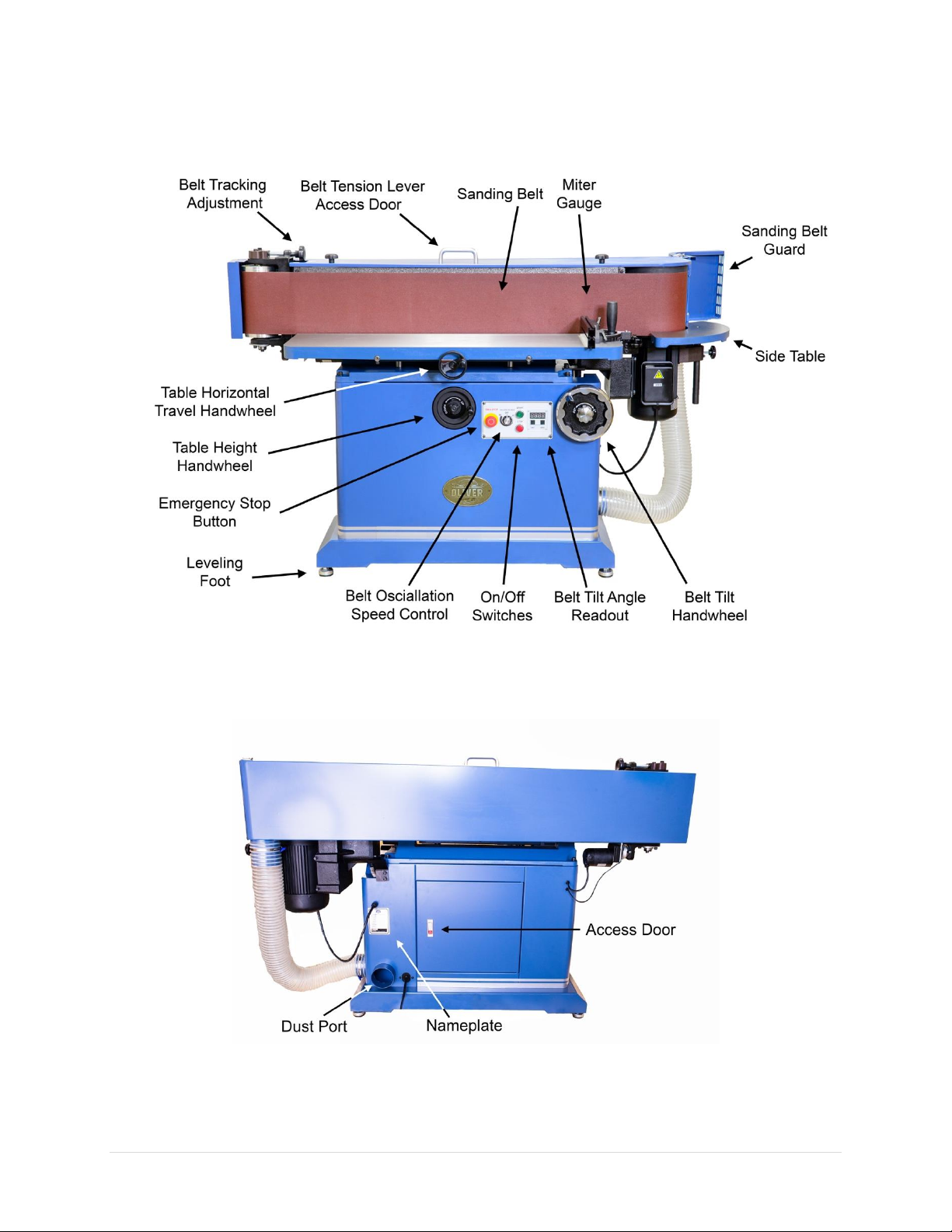
Identification ··········································· 8
Safety······················································ 9
General Safety Guidelines···························9
Safety Guidelines Specific to Sander··········11
Electricals ···············································12
Minimum Circuit Size Required for Model
6320 Sander·············································12
Grounding················································12
Electrical Wiring ·······································13
Setup······················································14
Shop Preparation······································14
Receiving··················································15
Inventory ·················································16
Lifting the Sander from the Pallet··············17
Cleaning···················································17
Sanding Belt Installation ···························18
Side Table Installation ······························19
Leveling the Sander ··································20
Dust Collection·········································20
Test Run···················································21
Mechanical Parts Inspection ···························21
Electronic & Electrical Components Testing ···22
Operation···············································23
Preparation Work·····································23
Adjustments·············································24
Belt Tilt Digital Readout Initialization··············24
Sanding Belt Tilt Adjustment···························24
Table Height Adjustment ································25
Edge Sanding············································26
Contour Sanding with Side Table···············27
Accessories ············································ 28
Maintenance ········································· 29
Lubricating Machine ·································30
Changing Sanding Belt ······························31
Belt Tracking Adjustment··························32
Troubleshooting····································· 33
Wiring Diagrams···································· 35
For Stock 6320.001 (230V 1Ph)··················35
For Stock 6320.003 (230V, 3Ph)·················36
Parts List················································ 37
Cabinet Stand···········································37
Head Plate················································38
Safety Guard System ································39
Table························································40
Miter Gauge·············································41
Maintenance Record······························ 50
Notes····················································· 52
Warranty and Service····························· 54

6320 Sander OLIVERMACHINERY.NET 5|Page
Introduction
Thank you for choosing Oliver! This manual contains important information on how to safely set up,
operate, and maintain this machine. Please take the time to read through this manual and make sure you
understand all instructions.
While this manual may provide tips on optimizing the result of your workpiece, the manual is not intended
as a substitute for formal woodworking training. If you need to know how to safely complete a
woodworking task, please consult knowledgeable and qualified sources before proceeding further.
We made every effort to keep this manual up-to-date. Instructions, specifications, drawings, and
photographs in this manual should match the machine delivered. If you find any differences or anything
that seems confusing in this manual, please check our website for an updated version:
WWW.OLIVERMACHINERY.NET/MANUALS
Alternatively, you can contact our technical support for help:
1-800-559-5065
Before calling, please note down the manufacture date and the
serial number of the machine. You can find the information on a
nameplate located on the back of the machine cabinet. This
information is needed to provide proper technical support and to
determine if an updated manual is available for your machine.
Please let us know how well this manual serves you. If you have any
suggestions, please call the number above or email us at:
We love to hear from our customers and make improvements.

6 | Page Oliver Machinery 6320 Sander
Specifications
Quick View
Model
6320 Sander
Stock Number
6320.001
6320.003
Power Requirement
230V 1Ph, 60Hz
230V, 3Ph, 60Hz
Motor
TEFC 3HP
Sanding Belt Size
9” x 138-1/2”
Sanding Belt Tilt
0° - 45°
Dimensions
84“(W) x 40”(D) x 44”(H)
Footprint
17”(W) x 42-1/8”(D)
Fully Assembled Weight
623 lbs.
Warranty
1 Year (Motor and electronics)
2 Years (All other parts)
Product Dimensions
Width x Depth x Height
(Min. Space Needed)
84“(W) x 40”(D) x 44”(H)
Footprint
17”(W) x 42-1/8”(D)
Fully Assembled Weight
623 lbs.
Shipment Info
Packaging
Wood Crate with Pallet Base
Content
Sander with Included Accessories
Dimensions
76-1/2”(L) x 30”(W) x 52-1/2”(H)
Weight
773 lbs.
Approx. Assembly Time
30 Minutes
Must Ship Upright
YES
Stackable
NO
Electricals
Stock Number
6320.001
6320.003
Power Requirement
230V, 1Ph, 60Hz
230V, 3Ph, 60Hz
Full Load Current Rating
12.5A
TBD
Recommended Circuit
Size
15A
TBD
Power Switch Type
ON/OFF Button Switch
Connection Type
NEMA 6-15 Plug with
6’14AWG Cord
Cord and plug are not included.
Electrical hookup by licensed
electrician required.

6320 Sander OLIVERMACHINERY.NET 7|Page
Motor
Motor Type
TEFC
Horsepower
3HP
Power Requirement
230V, 1Ph, 60Hz
230V, 3Ph, 60Hz
Full Load Current Rating
12.5A
TBD
Speed
1720 RPM
Efficiency / Power Factor
81% / 95.68%
TBD
Power Transfer Mechanism
Direct Drive
Bearing type
Permanently Sealed Ball Bearing
Sander
Sanding Belt Size
9” x 138-1/2”
Sanding Belt Speed
Approx. 4100FPM
Sanding Belt Tilt
0° - 45°
Sanding Belt Oscillation Stroke
13/64” – 25/64”
Oscillation Per Minute
0, 40-60
Sanding Belt Drive Wheel
9”Rubber Coated Aluminum
Sanding Belt Idler
5”Aluminum
Platen Construction
Precision Ground Cast Iron with Graphite Coated Backing
Platen Dimensions
45-1/2” x 10”
Table
Material
Precision Ground Cast Iron
Main Table Dimensions
46“(W) x 13”(D)
Main Table Height from Floor
33”–40-1/2”
Main Table Horizontal Travel
5”
Side Table Dimensions
19-3/8”(W) X 6”(D)
Side Table Height from Floor
33-1/2”–40”
Contour Sanding Drum Radius
4-1/2”
Miter Gauge
Angle Range
-60° to 60°, with detents at -45°, -30°, 0°, 30°, 45°
Miter Fence Length
12-3/4”
Safety
Number of Dust Ports
1
Dust Port Size
4”
Minimum CFM Required
650 CFM
Sound Rating @ 2’distance
107 dB
Others
Serial Number Location
On the back of the machine cabinet.
Certification
CSA 175370
Country of Origin
Taiwan

8 | Page Oliver Machinery 6320 Sander
Identification

6320 Sander OLIVERMACHINERY.NET 9|Page
Safety
Oliver Machinery has made every attempt to provide a safe, reliable, easy-to-use piece of machinery.
Safety, however, is ultimately depending on the individual machine operator. Before operating this
machine, please become familiar with the following safety labels and guidelines.
DANGER
This indicates an imminently hazardous situation which, if not avoided, WILL cause
death or serious injury.
WARNING
This means if the warning is not taken seriously, it CAN cause death or serious injury.
CAUTION
This means if the precaution is not taken, it MAY cause minor or moderate injury.
IMPORTANT
This is a tip for properly operating the machine to avoid machine damage.
General Safety Guidelines
1. FAMILIARIZE yourself with all safety instructions found in this manual. Know the limitations and
hazards associated with this machine. Do not operate/service this machine until you are properly
trained.
2. ELECTRICAL GROUNDING, when done properly, reduces the risk of electrocution, shocks, and fire.
Make certain that the machine frame is electrically grounded and that a ground lead is included in the
incoming electrical service. In cases where a cord and a plug are used, make certain that the grounding
plug connects to a suitable ground. Follow the grounding procedure indicated in the electrical code
of your area.
3. DISCONNECT the machine from power before performing any service, maintenance, adjustments, or
changing cutters. A machine under repair should be RED TAGGED to show it should not be used until
the maintenance is complete.
4. EYE PROTECTION: Always wear an approved safety face shield, goggles, or glasses that comply with
ANSI Z87.1 and CSA Z94.3 standards. Common eyeglasses are not safety glasses and may not provide
adequate protection.
5. EAR PROTECTION: Use hearing protective devices where the noise exceeds the level of exposure
allowed in Section 1910.95 of the OSHA Regulations. When in doubt, use it.
6. OTHER PERSONAL PROTECTION: Before the operation, remove tie, rings, watch, and other jewelry.
Roll up sleeves above elbows. Remove all loose outer clothing and confine long hair. Protective
footwear should be used. Do not wear gloves unless it is instructed to perform a particular step(s) in
the manual.
7. GUARDS: Keep machine guards in place for all applicable operations. If any guards are removed for
maintenance, DO NOT OPERATE the machine until all guards are reinstalled. Check clearance between
the guards and the cutter before starting the machine.

10 | Page Oliver Machinery 6320 Sander
8. WORKPLACE SAFETY: Keep the floor around the machine clean. Scrap material, sawdust, oil, and
other liquids increase the risk of tripping or slipping. Be sure to clean up the table before starting the
machine. Make certain the work area is well-lighted and that a proper exhaust system is used to
minimize dust. Use anti-skid floor strips on the floor area where the operator normally stands and
mark off the machine work area. Provide adequate workspace around the machine.
9. ACCESS CONTROL should be enforced so only trained personnel can access the work area and operate
the machine. Use a childproof power switch when applicable.
10. STAY ALERT at all times. Do not operate this machine while under the influence of drugs/alcohol or
when not feeling well.
11. NEVER STAND ON THE MACHINE. This prevents injuries from tipping-related accidents and accidental
contact with cutters.
12. REPLACEMENT PARTS: Use only genuine Oliver Machinery replacement parts and accessories
recommended for this machine. Generic parts made by other manufacturers may create a safety
hazard and WILL void the factory warranty and other guarantees.
13. PROPER USE: Do not use this machine for anything other than its intended use. If used for other
purposes, Oliver Machinery disclaims any real or implied warranty and holds itself harmless for any
injury or damage which may result from that use.
14. ADDITIONAL SAFETY INFORMATION:
•National Safety Council –Accident Prevention Manual for Business and Industry:
https://shop.nsc.org/apm-admin-program-14ed
•ANSI 01.1: https://webstore.ansi.org/standards/wmma/ansio12013
•OSHA 1910.213: https://www.osha.gov/laws-regs/regulations/standardnumber/1910/1910.213

6320 Sander OLIVERMACHINERY.NET 11 |Page
Safety Guidelines Specific to Sander
Before Work Begins:
1. Inspect the sanding belt for signs of failure. Replace damaged, overstretched, or worn sanding belts.
2. Ensure the sanding belt is tensioned.
3. Inspect the workpiece. Do not process workpieces with loose parts and/or containing dangerous
chemicals. Do not sand wood with high moisture content.
4. Ensure the table is positioned at least 1/16”above the bottom edge of the sanding belt.
5. Ensure the sanding belt guard, platen, and table are locked into position.
When Sanding:
1. Maintain control of the workpiece. Hold the workpiece firmly with both hands and apply light
pressure against the sanding belt. Use the sander table and miter gauge to support the workpiece.
2. Keep hands away from the sanding belt and other moving parts. Use special jigs to hold down small
workpieces as needed.
3. To avoid kickbacks and damaging the sanding belt, do not feed the workpiece with sharp corners
pointing against the moving direction of the sanding belt.
Correct
Wrong
After Operation
1. STOP THE MACHINE when the operator leaves the machine for any reason.
2. WAIT until both the main motor and oscillation motor come to a complete stop.
3. CLEAN UP before departure.

12 | Page Oliver Machinery 6320 Sander
Electricals
WARNING
All electrical work must be done by a licensed electrician and must meet the
electrical code in your area. Otherwise, the warranty is void.
Minimum Circuit Size Required for Model 6320 Sander
Stock
Number
Voltage
Phase
Minimum Circuit Size Required
6320.001
230V
1Ph
15A
6320.003
230V
3Ph
TBD
Please ensure the electrical circuit for this machine meets the minimum circuit size requirement. The
minimum circuit size requirement applies to a dedicated circuit that provides power to one 6320 Sander.
If more machines are sharing the same circuit, consult a licensed electrician to ensure the designated
circuit is properly sized for safe operation.
If a circuit is available but not meeting the minimum circuit size requirement listed above, a new circuit
must be installed for this machine.
Grounding
WARNING
Improper grounding can cause electric shock, fire, and equipment damage.
Proper grounding reduces the risk to the operator in the event of electrical malfunction or breakdown.
This machine must be connected to the grounding conductor when available, and all grounding
connections must meet or exceed the electrical code requirements in your area. Furthermore, all grounds
must be verified and must meet or exceed the electrical requirement of the machine.
For workshops that have a single phase system, If grounding is not available, consider the use of a GFCI
protection device as an alternative if this complies with the electric code in your area.
For workshops that have an ungrounded 3-phase system, a ground detector must be present according
to NEC 250.21(B).
Consult a licensed electrician to ensure this sander can operate safely before using this sander with an
ungrounded electrical system.

6320 Sander OLIVERMACHINERY.NET 13 |Page
Electrical Wiring
The single phase variant of his machine is pre-wired with a cord and a NEMA 6-15 plug. See “Wiring
Diagrams”on page 35 for wiring the three phase variant.
To connect the machine directly to the electrical panel (“Hardwiring”), ensure an electrical disconnect is
installed near the machine so the operator or service person can easily disconnect the machine from
power.
To connect this machine with a plug and a cord, use a UL/CSA listed plug that meets the power
requirements. Organize the power cord so it does not create a tripping hazard.
The use of an extension cord is not recommended. If you need to use an extension cord to connect to a
power source, select a durable cord type with a high-temperature rating (90C° or above). Use the
minimum amount of extension cord as needed.
Minimum cord size (AWG) required based on amperage draw and length of the cord:
Amps
Power Cord Length
25 feet
50 feet
75 feet
100 feet
8 to 12
14
14
12
10
12 to 15
12
12
10
10
15 to 20
10
10
10
NR
21 to 30
10
NR
NR
NR
*NR: Not Recommended
WARNING
Use properly sized wires that meet or exceed the power requirement of your
machine. Using undersized wires may cause overheating and increase the risk of fire
and machine damage.

14 | Page Oliver Machinery 6320 Sander
Setup
Shop Preparation
Space Requirement
The dimensions of this machine are 84“(L) x 40”(D). You will
need additional space for manipulating your workpiece,
electrical connection, and dust collection.
Keeping this sander several feet away from the wall allows
easy access to the backside of the machine for maintenance.
This also allows the sanding belt to tilt backwards.
Load Limits
This machine has a shipping weight of 773 lbs. and a net weight of 623 lbs. Please ensure all lifting tools
and building structures have adequate load capacity for transporting and supporting the total weight of
this machine, the operator, and related items.
Electricals
Make sure a properly sized circuit and electrical outlet are available near the machine. See “Electricals”
on page 12 for details regarding electrical requirements.
Lighting
Adequate lighting is needed for operating this machine. Overhead, non-glare lighting should be installed.
Safety Labels
If this machine introduces a new safety hazard to your workplace, display proper warning signs in highly
visible locations.
Dust Collection
Wood dust created by this sander is a health hazard. High-quality dusk masks should be available for using
the sander.
Connect this machine to a dust collection system. Check air suction strength regularly to ensure dust and
shavings are effectively removed.
CAUTION
Air resistance and leakage in a dust collection system impact its effectiveness. Use
a dust collection system that is rated above 650 CFM at the dust port. Doing so
improves air quality in the workplace and prevents the machine from jamming.

6320 Sander OLIVERMACHINERY.NET 15 |Page
Receiving
Your shipment should come in one crate. Upon receiving your shipment, check for any
significant damages before signing the delivery confirmation. If the crate is damaged,
or if the crate has a TILTWATCHTM indicator and the indicator turns RED:
1. Accept the shipment.
2. Make notes on the Bill of Lading before signing it.
3. Inspect for damage immediately and thoroughly. Document and take photos of all
damages found.
IMPORTANT
If the machine arrived damaged, please call us immediately at 1-800-559-5065.
Keep all the items, including the packaging, for damage inspection.
CAUTION
Always wear safety goggles and gloves when removing straps for securing your
package. Straps may spring back violently when released and cause injury.
Moving the Machine into the Shop
Your machine will be delivered by freight service, and it will be left outside of your workshop by default.
On the day of delivery, please be sure help is available to move the machine to its final location.
WARNING
6320 Sander has a gross weight of 773 lbs. and a net weight of 623 lbs.
Safe moving techniques and proper lifting equipment are required, or serious
personal injury may occur.
WARNING
Your machine may be secured by the packing straps. Do not lift your shipment by
the strap. They are not designed to hold the total weight of your shipment. They
may snap without warning and cause serious injury and machine damage.
Unboxing
Upon removing the crate cover, you should find the sander that is mostly assembled and protected by a
plastic bag. There is also a paper box that contains all loose parts and accessories.

16 | Page Oliver Machinery 6320 Sander
Inventory
Carefully unwrap the packaging and make sure all components are included in the shipment. Inventory all
items received and put them in groups.
Group 1 –Sanding Belt
Group 2 –Side Table
Group 3 –Knobs for Belt Tension Lever Access
Door
Group 3 –Side Table Knob
NOTICE: If you cannot find an item in the list above, please check if it is still attached to the packaging.
Occasionally, the item may have been pre-installed in the factory. See “Parts List” on page 37 to check if
a component is included or installed.
NOTICE: This machine comes with various standard-sized, non-proprietary parts. If any of these parts are
missing, we are happy to deliver them to you. To have the machine up and running as soon as possible,
you can also find these parts at your local hardware store.
Additional Items Needed for Machine Assembly
Item
Purpose
Safety glasses
Protection
Disposable gloves
Protection
Paper Towel
Cleaning
WD-40
Cleaning
Rust Inhibitor
Cast iron table top rust protection.

6320 Sander OLIVERMACHINERY.NET 17 |Page
Lifting the Sander from the Pallet
The sander is mounted on the pallet to stabilize
the machine during transport. Remove the two
retaining brackets from each side of the sander
before lifting the sander from the pallet.
Connect the lifting slings to the lifting eye bolts
and ensure the slings are balanced, then lift the
sander from overhead and move to the
designated location for operation.
Lower the sander gently to the floor to prevent
damaging the leveling feet and the cabinet.
Cleaning
To prevent rusting during shipment, the
unpainted cast iron main table and end table are
covered with rust protectant and plastic film.
A part of the plastic film is held in between the
main table and the miter gauge. Remove two
socket cap screws to unmount the miter gauge
temporarily to release the plastic film and clean
the entire table.
Wipe off the rust protectant with paper towels.
Using WD-40 can help to dissolve the rust
protectant and make it easier to remove.
Once all rust protectant is removed, routinely
coat the tabletops with rust preventive such as
Boeshield® T-9 or paste wax. Do not use rust
preventives that contain silicone, which is known
to interfere with certain finishes and glues.
After the tables are cleaned, wipe off the excess
oil at the bottom of the miter gauge and re-
mount the miter gauge.

18 | Page Oliver Machinery 6320 Sander
Sanding Belt Installation
1. Remove the eye bolts for lifting the sander
and open the belt tension lever access door.
2. Pull up the belt tension lever to install a
sanding belt.
3. The sanding belt runs in a counter-clockwise
direction. Make sure the arrows on the back
of the sanding belt align with the belt
running direction.
4. Loosen the lock knob under the belt guard to
open the guard.
5. Slip the belt evenly and gradually into both
drums until the belt is sitting in the middle of
the drums.
6. Tighten the sanding belt by moving the belt
tensioning lever back to its original position.
When the sanding belt is properly tensioned,
it should not slip off from the drums.
7. Close the belt guard and lock the guard with
the lock knob.
8. Close the belt tension lever access door.
Instead of reinstalling the eye bolts, install
the pair of knobs provided to lock the door.
Keep the eye bolts so the sander can be
safely moved in the future.

6320 Sander OLIVERMACHINERY.NET 19 |Page
Side Table Installation
1. To maximize dust collection efficiency, only
install the side table for contour sanding
work.
2. Loosen the lock knob to unlock the sanding
belt guard.
3. Use the buckle on top of the sanding belt
guard to keep the guard in the open position.
4. Install the side table lock knob onto the
mounting bracket.
5. Insert the end table post into the mounting
bracket. Align the groove of the post with
the lock knob.
6. Make sure the table is not catching the
sanding belt and the table is set above the
bottom edge of the belt. Then tighten the
lock knob to secure the table.
7. After using the side table, remove it from the
sander. Close and lock the sanding belt
guard.

20 | Page Oliver Machinery 6320 Sander
Leveling the Sander
This sander should be positioned on a level, stable floor. If
the machine is rocking on the floor or if it vibrates
excessively during operation, please adjust the rubber
leveling feet with a 19mm wrench to level the machine.
Test the adjustments to make sure the machine does not
rock on the floor.
Dust Collection
This sander can generate a lot of dust. Connect this
machine to a dust collection system. Whenever possible,
use the sander with the sanding belt guard closed to
maximize dust collection efficiency.
The minimum CFM requirement for this sander is 650 CFM
at the dust port, which means the dust collection system
should have a rating greater than 650 CFM, as air friction
and leakage can reduce effective CFM at the dust port.
IMPORTANT
Running this sander without a dust collection system or using a dust collection
system with inadequate suction may damage the machine and cause other
hazardous situations. Check your dust collection system regularly to make sure it
is not jammed or filled up.
Table of contents
Other Oliver Sander manuals
Popular Sander manuals by other brands

DeWalt
DeWalt DWE6421 instruction manual

King Canada
King Canada KC-702CN instruction manual

Fast Mover
Fast Mover FT1075 Product instruction manual

Westfalia
Westfalia 85 88 46 instruction manual

Craftsman
Craftsman 21181 - 8 in. Bench Buffer Operator's manual

Porter-Cable
Porter-Cable 7435 instruction manual