Olsen Flex Quality User manual


Index
1 - Introduction............................................................................................................................................................5
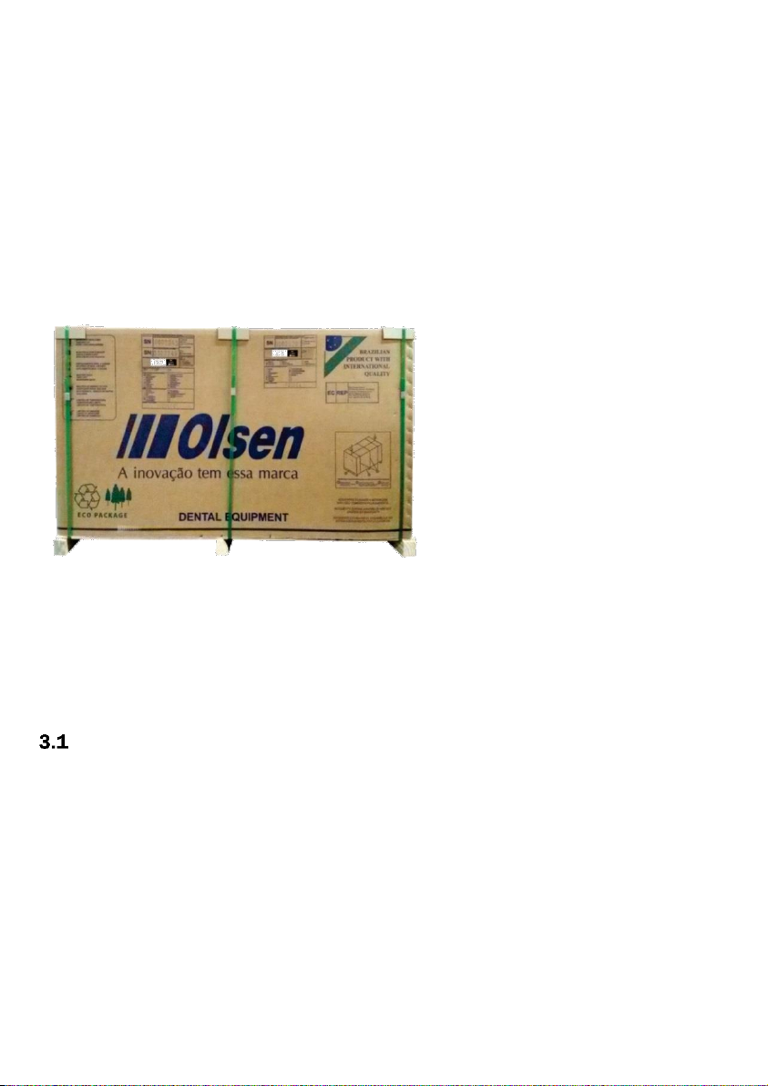
2 - Package Contents..................................................................................................................................................5
3 - Equipment Presentation........................................................................................................................................5
- Standard Configuration................................................................................................................................5
3.1.1 - Dental Chair........................................................................................................................................5
3.1.2 - Operating Light...................................................................................................................................5
3.1.3 - Delivery System..................................................................................................................................5
3.1.4 - Water Unit...........................................................................................................................................5
- Optional Items..............................................................................................................................................6
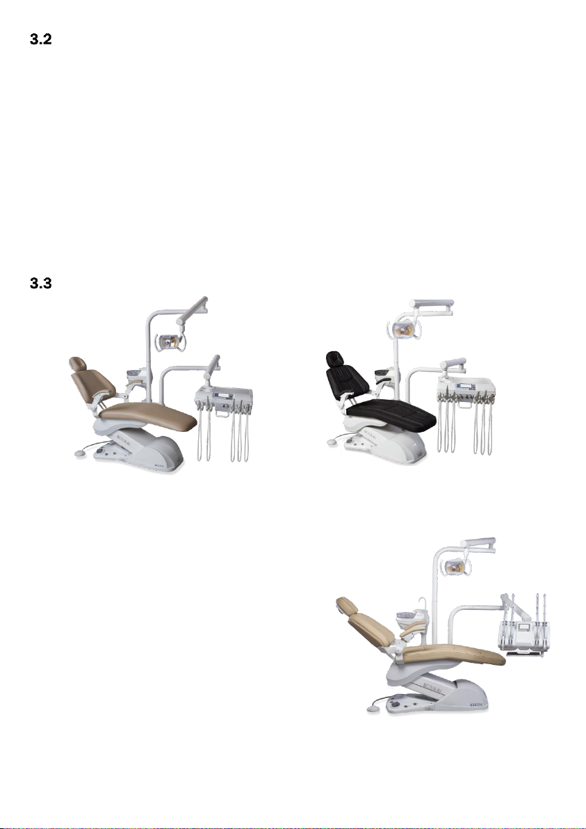
- Quality Models..............................................................................................................................................6
3.3.1 - Quality Flex .........................................................................................................................................6
3.3.2 - Quality EX............................................................................................................................................6
3.3.3 - Quality Cross Flex ...............................................................................................................................6
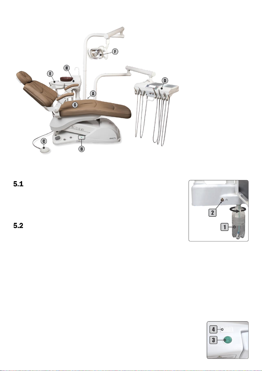
4 - Parts Identification.................................................................................................................................................7
5 - Equipment Operating and Description..................................................................................................................7
- Before Turning On the Equipment...............................................................................................................7
- Turning On the Equipment...........................................................................................................................7
5.2.1 - Delivery System..................................................................................................................................7
5.2.2 - Electric Panel......................................................................................................................................7
- Base and Progressive Pedal Controls (Operation)......................................................................................8
5.3.1 - Remote Foot Pedal Commands (Opcional) .......................................................................................8
- Working Table...............................................................................................................................................8
5.4.1 - Quality Working Table ........................................................................................................................8
5.4.2 - Working Table Quality Cross Flex.................................................................................................... 10
- Operating Lights........................................................................................................................................ 11
5.5.1 - Concept LED.................................................................................................................................... 11
5.5.2 - Concept Plus (Optional) .................................................................................................................. 11
5.5.3 - Premium LED (Optional).................................................................................................................. 11
- Water Unit and Assistant Module (Optional)............................................................................................ 11
- Dental Chair .............................................................................................................................................. 12
5.7.1 - Zero Position.................................................................................................................................... 12
5.7.2 - Work Position .................................................................................................................................. 12
5.7.3 - Headrest .......................................................................................................................................... 12
5.7.4 - Swivel Right Armrest (Optional) ...................................................................................................... 13
6 - Instruments Operation........................................................................................................................................ 13

- Pneumatic Handpiece Couplings ............................................................................................................. 13
- Optical Fiber Handpiece (Optional) .......................................................................................................... 13
- Electrical Micromotor (Optional)............................................................................................................... 13
6.3.1 - Electrical Micromotor Basic Adjustments....................................................................................... 13
6.3.2 - Brushless Electrical Micromotor - Built in (Optional) ..................................................................... 14
6.3.3 - Brushless Electrical Micromotor - Side Panel (Optional) ............................................................... 14
- Scaler......................................................................................................................................................... 15
6.4.1 - Standard Scaler............................................................................................................................... 15
6.4.2 - Scaler with LED Light (Optional) ..................................................................................................... 15
6.4.3 - Scaler Adjustments - Operation and Basic Adjustments............................................................... 16
6.4.4 - Scaler Tips ....................................................................................................................................... 16
- Curing Light (Optional) .............................................................................................................................. 16
- 3-Way Syringe............................................................................................................................................ 16
- Venturi Saliva Ejector................................................................................................................................ 17
- High Power Saliva Ejector Vórtice (Optional)............................................................................................ 17
- Vacuum Pump Adaptor (Optional) ............................................................................................................ 17
Prophylaxis System................................................................................................................................... 17
6.10.1 - Bicarbonate Jet (Optional) ............................................................................................................ 17
6.10.2 - Prophy-Jet System (Optional)........................................................................................................ 17
- Air Jet System (Optional)......................................................................................................................... 18
- X-Ray Viewer............................................................................................................................................ 18
- Thermo Comfort System (Optional)........................................................................................................ 18
- Anti-Stress System (Optional)................................................................................................................. 18
- Monitor Holder (Optional)....................................................................................................................... 19
- Cart System (Optional)............................................................................................................................ 19
7 - Symbology ........................................................................................................................................................... 20
8 - Olsen Accredited Technical Assistance Network............................................................................................... 21
9 - Warranty Terms................................................................................................................................................... 22
10 - Message from the President............................................................................................................................ 23

5
1- Introduction
Congratulations on choosing Olsen equipment!
You have acquired high-tech equipment developed to offer the best performance in dental procedures
ensuring ergonomics and comfort, for both professional and the patient.
The purpose of this guide is to present instructions for operating the dental equipment of the Quality line.
The images are merely illustrative and do not represent the configuration of models or the availability of items
and accessories.
The User Manual Dental Line is supplementary to this guide and should be read before operating the
equipment. It is provided in digital format (PDF) along with the order confirmation for your equipment. The user
manual presented the descriptive and technical information, installation instructions, maintenance, cleaning,
precautions of use and regulatory guidelines.
2- Package Contents
Check out the equipment package contents:
Standard Items:
1 Dental Chair Quality
1 Delivery Unit Quality
1 Operating Light
1 Packing Support
1 Dental Stool
1 Quality Quick Operation Guide
Optional Items:
Handpieces and Accessories
Separated Junction Box
Cart System
Additional Stool
Monitor Holder
Note:
1 -Items availability in the packaging may change in the case of the customer order.
2 -Handpieces: dental instruments acquired with the equipment described in the purchase order and invoice of
the product, according to customer request.
3- Equipment Presentation
- Standard Configuration
3.1.1 - Dental Chair
3 programmable Work Positions
Automatic Zero Position
Joystick and Commands on the Chair Base
Integrated Junction Box
Multi-articulated Headrest
Swivel Right Armrest
3.1.2 - Operating Light
Concept LED 8.000 to 30.000 Lux
On/Off on the Base and Control Panels
Side Handles
Multifaceted Mirror
3.1.3 - Delivery System
Coupling for Low and High-speed Handpiece
3-Way Syringe
Stainless Steel Tray
Flex Arm with Pneumatic Lock and Capacitive
Sensor
Instruments Water Tank with Solids Filter
X-Ray Viewer
3.1.4 - Water Unit
Swivel at 90º
Translucent Spittoon Bowl
Cup Filler
Venturi Saliva Ejector of Ø6,5 mm and Ø9,5 mm

6
- Optional Items
Leather Upholstery
Anti-Stress System
Automatic Vapor Drain
Ambidextrous Delivery System
Additional Handpiece Coupling
LED Curing Light
Blue Touch Panel
Air Jet System
Prophy-Jet System
Electrical Micromotor
Brushless Electrical Micromotor
Coupling for Optical Fiber Handpiece
Premium LED Operating Light 8.000 to 30.000 Lux
Concept Plus Operating Light 8.000 to 30.000 Lux
Scaler with LED Light
Standard Scaler
Thermo Comfort System
Monitor Holder
Assistant Module
Porcelain Spittoon Bowl
Spittoon Cup Filler with timer
Additional 3-Way Syringe on the Water Unit or
Assistant Module
High Power Vórtice Saliva Ejector
Vacuum Pump Adaptor Set
Midwest Couplings
Cart System
Prophylaxis System with Bicarbonate Jet
Remote Foot Pedal
Note: optional items are defined on the customer's order.
- Quality Models
3.3.1 - Quality Flex
It presents the standard items of the Quality line
(section 3.1).
3.3.2 - Quality EX
It presents, in addition to the standard items of the
Quality line (section 3.1):
Additional Handpiece Position
Standard Scaler
Prophylaxis System with Bicarbonate Jet
Blue Touch Panel
Bowl Flush Water Control and Cup Filler with Timer
3.3.3 - Quality Cross Flex
It presents, in addition to the standard items of the
Quality line (section 3.1):
Cross Flex Working Table with Jointed Stainless Steel Tray
Additional Handpiece Position
Bowl Flush Water Control and Cup Filler with Timer
Quality Flex
Quality EX
Quality Cross Flex

7
4- Parts Identification
A - Delivery System
(Item 5.2.1 - pg. 7)
B - Electrical Panel
(Item 5.2.2 - pg. 7)
C -Progressive Pedal
(Item 5.3 - pg. 8)
D - Working Table
(Item 5.4 - pg. 8)
E -Assistant Module
(Item 5.6 - pg. 11)
F - Operating Light
(Item 5.5 - pg. 11)
G - Dental Chair
(Item 5.7 - pg. 12)
H - Water Unit
(Item 5.6 - pg. 11)
5- Equipment Operating and Description
- Before Turning On the Equipment
1º - Check if the equipment is properly installed in accordance to the instructions
in the chapter 6 (Installation) of the User Manual Dental Line;
2º - Turn On the air compressor that supplies the equipment;
3º - Open the main water supply valve of the equipment;
4º - Turn On the equipment's power circuit breaker.
- Turning On the Equipment
1º - Turn the On / Off switch (3), its LED indicator will light;
2º - Activate the "Seat Up" command (section 5.3) on the chair base until the
seat reaches its maximum height limit;
3º - Close the pressure valve (2);
4º - Remove the water tank (1) and make sure it filled with water. If necessary, fill it with drinkable water up to
the limit indicated in tank and reattach it again. If you wish to place prophylactic products (low
concentration);
5º - Open the pressure valve (2) and check if the water tank (1) is well attached and free of leaks;
6º - Before starting the use equipment, verify the operation of all instruments and commands available and
perform the cleaning and sterilization of the instruments (chapter 7 of the User Manual Dental Line –
Cleaning and Disinfection).
5.2.1 - Delivery System
1 -Water Tank
2 -Pressure Valve
5.2.2 - Electric Panel
3 -On/Off Switch with LED Indicator
4 -Fuse Holder

8
- Base and Progressive Pedal Controls (Operation)
1 -Zero Position
2 -Work Position
3 -Backrest Up ( )
4 -Seat Down ( )
5 -Backrest Down ( )
6 -Seat Up ( )
7 -On/Off Operating Light
8 -Spittoon Bowl Flush
9 -On/Off Vórtice Saliva Ejector
10 -Progressive/Activation Pedal
To activate each command simply press the
respective button or in the case of the movements
of the chair, press the joystick at the points
indicated in the side image (3to 6).
In case of the equipment has the high-power
Vórtice saliva ejector, the spittoon bowl flush command (8) will be placed on the water unit, and the command
for Vórtice ejector (9) will be available on the chair base.
To activate the handpieces: press the progressive/activation pedal (10).
5.3.1 - Remote Foot Pedal Commands (Opcional)
1 -Seat Up ( )/Position 1
2 -Backrest Up ( )/Position 2
3 -Seat Down ( )/Position 3
4 -Backrest Down ( )
5 -Work Position
6 -Zero Position
7 -Propulsion/Activation Pedal
8 -Cup Filler
9 -On/Off Vórtice Saliva Ejector
10 -On/Off Operating Light
11 -Spittoon Bowl Flush
12 -Metal Handle
- Working Table
5.4.1 - Quality Working Table
1 -Command Panel
2 -Instruments Control Panel
3 -On/Off Optical Fiber/Air Jet System
4 -On/Off Thermo Comfort System
The layout of the controls and panels may vary according customer order and available handpieces.

9
Command Panel Models (1)
Instruments Control Panel (2):
* The pneumatic brake valve of the flex arm is an optional item that is available when the system does not have
the capacitive system.
Blue Touch Panel with X-Ray Viewer
1 -Seat Up/Position 1
2 -Backrest Up/Position 2
3 -Seat Down/Position 3
4 -Backrest Down
5 -Work Position
6 -Zero Position
7 - Spittoon Bowl Flush
8 -Cup Filler
9 -On/Off Operating Light
10 -X-Ray Viewer
11 -On/Off X-Ray Viewer
X - Ray Viewer
1 -Electrical Micromotor Speed Control
2 -Electrical Micromotor Direction Control
3 -Scaler Power Control and Function Selector - General-Perio/Endo
4 -Scaler Water Control
5 -On/Off Thermo Comfort LED
6 -Optical Fiber Water Control
7 -Brushless Micromotor Water Control
8 -Pneumatic Brake Valve*

10
5.4.2 - Working Table Quality Cross Flex
1 -Top Panel Cross
2 -Command Panel
3 -Instruments Control Panel
The layout of the controls and panels may
vary according customer order and
available handpieces.
These controls are provided below the instrument to which they refer.
1 -Seat Up/Position
2 -Backrest Up/Position
3 -Seat Down/Position
4 -Backrest Down
5 -Work Position
6 -Zero Position
Command Panel (2):
7 -Spittoon Bowl Flush
8 -Cup Filler
9 -On/Off Operating Light
10 -On/Off Optical Fiber Light
11 - On/Off Air Jet System
12 - On/Off Thermo Comfort System
1 -X-Ray Viewer
2 -On/Off X-Ray Viewer
Top Panel Cross (1):
1 -Electrical Micromotor Speed Control
2 -Electrical Micromotor Direction Control
3 -Scaler Power Control and Function Selector - General-Pério/Endo
4 -Scaler Water Control
5 -Optical Fiber Water Control
Instruments Control Panel (3):

11
- Operating Lights
5.5.1 - Concept LED
To turn On/Off the operating light: press the operating light
control (1) on the chair base (section 5.3) or command panel
(section 5.4).
To change the light intensity: hold the operating light control button pressed
for more than 2 seconds.
5.5.2 - Concept Plus (Optional)
To activate the operating light: press the
operating light command (1) on the chair base
(section 5.3) or on the command panel
(section 5.4) to enable sensor (3) and control
lever (2).
To turn On/Off the operating light: pass
the hand in front of the sensor (3)
approximately 5 cm away or turn to left or right
the control lever (2).
To change the light intensity: hold your hand in front of the sensor (3) or
hold the control lever (2) to the left or to the right until the operating light shows the desired intensity.
5.5.3 - Premium LED (Optional)
To activate the operating light: press the operating light command (1)
on the chair base (section 5.3) or on the command panel (section 5.4) to
enable sensor (5) and control knob (4).
To turn On/Off the operating light: pass the hand in front of the
sensor (5) approximately 5 cm away or press the control knob (4).
To change the light intensity: hold your hand in front of the sensor (5)
or turn the control knob (4) until the operating light shows the desired
intensity.
- Water Unit and Assistant Module (Optional)
The water unit may display water controls for the bowl flush and cup filler according to the equipment
configuration. The cup filler water spout is removable.
To control the flow of water for cup filler (2) and spittoon bowl (1), the water unit provides a needle
valve (3).
The availability of commands and instruments on water unit
or assistant module may vary according customer order and
available handpieces.
When the equipment has assistant module, the instruments of the
water unit are transferred to the module, facilitating access for the operator, through the extension arm.
1 -Cup Filler Control
2 -Spittoon Bowl Control
3 -Water Unit Valve
4 - Assistant Module
5 - Vacuum Pump Adaptor
3 -Venturi Saliva Ejector

12
- Dental Chair
1 -Seat Up ( )
2 -Seat Down ( )
3 -Backrest Down ( )
4 -Backrest Up ( )
To move backrest and seat: use the joystick buttons 1 to 4, located on
the chair base (section 5.3) o panel Blue Touch (optional).
5.7.1 - Zero Position
Press the Zero Position key to automatically adjust the seat to the lowest position and
backrest in the highest position simultaneously, to facilitate patient entry and exit.
5.7.2 - Work Position
To save a work position:
1º - Press the Zero Position key;
2º - Adjust the backrest to the desired position;
3º - Adjust the seat to the desired position;
4º - Press the Work Position key for 5 seconds. The equipment will emit 2 long beeps;
5º - Press command 1 (Seat Up) while the equipment beeps; The equipment will emit 2 short beeps to confirm
the procedure;
Note: the time to record the working position is only 2 seconds between steps 4 and 5, then when you hear the
first long beep (step 4), quickly press one of the available commands (1 to 3) to record the working position. If
none of the available commands are pressed during this time, the equipment will emit 3 short beeps, canceling
the operation.
6º - Press the Zero Position key.
Repeat the previous steps by replacing the command 1 by the command 2 (Backrest Up) to record the
working position 2 or by the command 3 (Seat Down) to save the working position 3.
To perform a working position:
1º - Press the Work Position key; The equipment will emit a short beep;
2º - Press the command for the desired saved working position (1 to 3); The equipment beeps twice confirming
the operation.
The dental chair moves the backrest and seat simultaneously to the previously saved position and lights
the operating light at the last intensity used.
Note: after pressing the Work Position key, the time for position selection is 4 seconds. If no key is pressed
within this time, the equipment cancels the operation.
5.7.3 - Headrest
To adjust the headrest (2) position: turn the knob (1) counterclockwise,
adjust the headrest (2) in the desired position. Turn the knob (1) clockwise to lock
the headrest in the set position.
To adjust the height of the headrest (3): move the bar (3) until you reach the
position. The headrest bar allows adjustment with up to 17 cm from the backrest.

13
5.7.4 - Swivel Right Armrest (Optional)
To move the swivel armrest: press the trigger (1) and push the armrest down.
6- Instruments Operation
- Pneumatic Handpiece Couplings
Before starting the operation connect the handpiece (1) to
the coupling by attaching it to the coupling ring (2), ensuring that
it is properly connected and that there is no leakage of air or
water.
To activate the rotation: press the propulsion/activation
pedal (5). The higher the pressure applied to the pedal, the more
speed in the handpiece, until reaching the pressure limits of the
equipment.
To adjust the spray: turn the adjusting ring (4) until the desired volume of water. To
adjust the maximum flow of water, bring the spray adjustment indicators (3) closer to each
other. To decrease the flow of water, rotate the ring so it distances one indicator from the other. The completely
opposite points indicate the minimum water regulation for the spray.
- Optical Fiber Handpiece (Optional)
Before starting the operation connect the optical fiber
handpiece to the coupling by attaching it to the coupling
ring (1), ensuring that it is properly connected and there is
no leakage of air or water.
To activate the rotation: press the
propulsion/activation pedal (2). The higher the pressure
applied to the pedal, the more speed in the handpiece, until
reaching the pressure limits of the equipment.
To turn the coupling’s light On/Off: use the On/Off
optical fiber light (3) on the command panel (section 5.4) or
the On/Off key (4) on the left side of the working table (section 5.4).
To adjust the spray: use the optical fiber water control knob (5) on the
instruments control panel.
- Electrical Micromotor (Optional)
Before starting the operation, connect the handpiece to
the electrical micromotor (2).
To activate the rotation: press the progressive/activation
pedal (1).
6.3.1 - Electrical Micromotor Basic Adjustments
To adjust the speed: turn the control knob (3) until the desired speed
is reached.
To change the rotation direction: use the rotation direction control (4).
FWD: clockwise; OFF: Off; REV: counterclockwise.

14
6.3.2 - Brushless Electrical Micromotor - Built in (Optional)
Before starting the
operation, connect the handpiece to
the electrical micromotor (8).
To activate the rotation: press the
propulsion/activation pedal (7).
To select the transmission: use the Select key (5). The
selection is indicated by LED’s (3): 20: 1; 1: 1 and 1: 5.
To reverse the rotation: use the Reverse key (1).
To adjust speed: use the adjustment key (4) The speed relation of each transmission with the value of the
display (2) is indicated in the side table.
Example:
Display value: 15
Selected gear ratio: 1:1 Factor: x1.000
Rotation speed: 15 x 1000 = 15.000 rpm
To activate memory: press the desired Memory key (6). The display will show the speed and the LED will
indicate the present transmission.
To record memory: select the transmission and adjust the speed of rotation to store. Press and hold one
of the Memory key (6) until the system emits 2 beeps, indicating that the memory has been recorded.
To save the second available memory repeat the same procedure.
To adjust the electrical micromotor water: use the water control knob (9) on the instruments control
panel.
6.3.3 - Brushless Electrical Micromotor - Side Panel (Optional)
Before starting the operation, connect the
handpiece to the electrical micromotor (16).
To activate the rotation: press the
propulsion/activation pedal (14) or the Manual
Start key (11).
To select a preset program: use the Program
key (8). There is 7 programs available, according
the table below:
The selected program is shown on the display (1).
To record program: select program P1 or P2, then select the desired
gear ration and adjust the speed. Press and hold the Program key (8) until the confirmation of the system.

15
To adjust speed: use the adjustment keys (13) to increase or decrease speed. Please see the table below
for speed range for each gear ration value.
The selected program is shown on the display (5).
To select the gear ratio: use Gear Ratio key (10). There are the
following values available: 1:5, 1:1, 4:1, 10:1, 16:1 and 20:1.
The selected gear ratio is shown on the display (4).
To change the rotation direction: use the Direction key (9).
The selected direction is shown on the display (3).
To adjust the micromotor water: use the water control
knob (15) on the instruments control panel.
To access setup menu: press and hold the Setting key (12).
Use the Setting key (12) to select the desired option.
To adjust LED options: use the adjustment keys (13) to set
the parameter.
To adjust pneumatic activation method: use the adjustment keys (13) to set the parameter.
To adjust Input pneumatic pressure: use the adjustment keys (13) to set the parameter.
Note: the micromotor system preset by the factory according to the internal equipment pressure. It is not
recommended to change the pressure parameters.
- Scaler
6.4.1 - Standard Scaler
To start the use of scaler it is necessary to first install
the tip that will be used, according to the instructions in
section 6.4.2.
To activate the scaler: it is necessary to remove the
scaler from the support and press the propulsion/activation
pedal (6).
Observe the settings for scaler in section 6.4.3.
The standard scaler is not removable.
6.4.2 - Scaler with LED Light (Optional)
For the use of scaler, it is necessary to connect the
transducer (1) to the coupling (3) and install the tip on the
transducer (1).
To attach the transducer (1) to the coupling: align the
adjustment indicators (2) of the two parts and carefully insert them.
To install the scaler tips: insert the tip into the transducer (1) by threading it carefully,
then insert the Torque wrench (4) into the tip and then rotate it clockwise until it is tight. To
remove the tip, turn it counterclockwise with the Torque wrench (4).
To install a file adapter (not supplied with scaler): attach the adapter to the transducer (1) and screw it
gently. Insert the file into the tip of the adapter, thread the tip and then use the Endo wrench (5) to tighten. To
remove the adapter, use the Endo wrench (5) to loosen it and then carefully unscrew.
LED Off
LED On
without delay
LED On
with 10s delay
When pedal (14) is pressed micromotor
performs the maximum speed adjusted
Micromotor performs speed according to
the pressure on the pedal (14)
Set minimum activation pressure
from 0.03 to 0.10 MPa
Set maximum input pressure
from 0.20 to 0.40 MPa
Reverse
Forward

16
6.4.3 - Scaler Adjustments - Operation and Basic Adjustments
To activate the scaler: push the propulsion/activation
pedal (6).
To adjust the vibration power: turn the control knob (7)
until the desired power is reached.
To toggle functions: push the control knob (7) in
direction of the table for "GP" function (General - Perio). Pull the
knob gently in the opposite direction of the table for "E" (Endo)
function.
To adjust the water: use the control button (8) on the instrument control panel.
6.4.4 - Scaler Tips
The tips GD1, PD1 and PD3 accompany the scaler. The power and application information for each tip is
available in the table below.
Note:
1 -Do not use the tip on features other than those specified by the manufacturer.
2 -Do not exceed the power limit for each tip. That could damage the tip and the scaler.
- Curing Light (Optional)
Before starting the curing light use, install the
tip (1) and the light hood (2).
To install the tip: first, attach the light hood (2)
to the tip and then attach it to the curing light
unit (3). The tip must be pushed all the way to the fitting end.
To activate/deactivate the curing light: press the On/Off button (5) twice. The
green LED (4) indicates that the curing light is operating. The curing light unit will
run for 20 seconds and will turn Off automatically.
To toggle the operating mode: each tap on the selection button (9) switches
the operation mode. Press the selection button (9) until the orange LED indicates
the desired mode.
The curing light operates in the following modes:
−Continuous (6): turns on the maximum power for 20 seconds;
−Ramp (7): turns on the minimum power, gradually increasing. In 5 seconds
reaches its maximum power until the cycle of 20 seconds is finished;
−Pulse (8): the device blinking for 20 seconds.
- 3-Way Syringe
Before beginning the use of the 3-way syringe (5), connect the
syringe tip (3) by pressing the locking ring (4) into the correct fit.
To emit air jet: press the air button (1).
To emit water jet: press the water button (2).
To emit spray jet: press simultaneously the air and water
buttons (1and 2).

17
- Venturi Saliva Ejector
To activate the suction: remove the ejector (2) from the holder (1).
To deactivate the suction: place the ejector in its holder (1).
The cannula adapter (3) is removable for cleaning.
- High Power Saliva Ejector Vórtice (Optional)
Before starting the operation with the Vórtice saliva
ejector (2), insert the cannula into the adapter (3).
To enable/disable suction: use the On/Off Vórtice saliva
ejector button (1) on the chair base.
The cannula adapter (3) is removable for cleaning.
- Vacuum Pump Adaptor (Optional)
To activate suction: remove the vacuum pump suction (2) from its
holder (1).
To adjust suction flow: to decrease the suction flow, turn the
adaptor's body (3) away from the indicators (4). The more distant, the
smaller the suction. For the maximum suction flow, align the indicators (4).
To deactivate the suction: place the vacuum pump in its holder (1).
The cannula adapter (5) is removable for cleaning.
Prophylaxis System
6.10.1 - Bicarbonate Jet (Optional)
Before starting use of the bicarbonate jet,
its necessary deposit bicarbonate sodium in the
reservoir (4), check for moisture in the filter (8) and
connect the bicarbonate jet handpiece (3) to its
coupling (2).
To fill the bicarbonate reservoir: open the reservoir (4) by
turning the cover (6) anticlockwise and deposit the bicarbonate
sodium until to the red line (5). Close the reservoir.
To remove condensed water in the filter: press the valve (7)
on the base of the filter (8) to drain the water.
To activate/deactivate the bicarbonate jet: press the
progressive/activation pedal (1). The more pressure on the pedal,
the greater the volume of the jet emitted by the handpiece. until
reaching the pressure limits of the equipment.
To adjust the spray: see section 6.1.
Clean the sodium bicarbonate tank (4) at the end of each procedure.
6.10.2 - Prophy-Jet System (Optional)
Before starting the Prophy-Jet system (3) use, deposit up
to 15g of sodium bicarbonate for dental use in the sodium
bicarbonate reservoir (4) and attach the Prophy-Jet to the
pneumatic coupling available on the assistant module or
pneumatic coupling (2) for low-speed handpiece in the working
table.
To activate/deactivate: press the progressive/activation
pedal (1). The higher the pressure applied to the pedal, the
higher the air volume of the jet emitted by the Prophy-Jet system,
until reaching the pressure limits of the equipment.
Clean the sodium bicarbonate tank (4) at the end of each procedure.

18
- Air Jet System (Optional)
To activate/deactivate the Air Jet system: press the button (2) on the left side of the
working table. (section 5.4).
Note: if the working table is provided with optical fiber coupling, the button for Air Jet system
activation is the same switch for On/Off optical fiber coupling light.
On the working tables with Blue Touch panel, use the Air Jet key (1).
To activate/deactivate the Air Jet system on the Blue Touch panel: use the On/Off Air
Jet key (1) on the command panel. When Air Jet system is activated, the continuous air jet
starts as soon as the handpiece is removed from the holder.
When pressing the propulsion/activation pedal, the system is interrupted, and the handpiece operates
normally. When releasing the pedal, the air jet will restart until the system is turned Off or the handpiece is
placed in its holder.
- X-Ray Viewer
To turn On the x-ray viewer: press the On/Off key (1) on the command panel.
- Thermo Comfort System (Optional)
To activate the Thermo Comfort: press the button (1) on the right side of
the working table (section 5.3). The green LED (2) on the instrument panel will
light up.
To activate the on working tables with Blue Touch Panel: use the Thermo
Comfort key (3). Above the button, the green LED (2) will light to indicate that
device is operating. (section 5.4).
When the device is started, wait for approximately 10 minutes for the
initial heating of the water.
- Anti-Stress System (Optional)
To activate/deactivate Anti-Stress system: press the “On/Off” key (5).
To enable the automatic massage system: press the “AUT” key (3). The
system will start executing 14 types of massage combinations, alternating
one combination every minute.
To toggle massage combinations: use the “AJUSTES” keys (8) while
performing automatic massage to advance or repeat the desired massage
combination.
To adjust the massage time: press the “TEMPO” key (6) and then use
the “AJUSTES” key (8) to adjust the duration of the massage (from 5 to
45 minutes).
To adjust the vibration power: press the “POTÊNCIA” key (7) and then
use the “AJUSTES” key (8) to adjust up to 10 levels of vibration intensity for
the massager’s motors.
To enable/disable massagers: use the “PONTO” key (4) to define which
massagers should work during the massage. Use the “AJUSTES” key (8) just
after the “PONTO” key (4) to customize the running massages. The LED’s (2)
indicated the motor that will be active.
To restore factory settings: press the “AUT” key (3) twice quickly.
20 seconds after the last command executed, the display (1) will
show the initials AU, but without affecting the programming in
progress.

19
- Monitor Holder (Optional)
The monitor holder features a rotation on the axis, tilt
adjustment and lateral rotation for the monitor.
The monitor is not part of the monitor holder.
Do not use on the monitor holder:
1 -Equipment powered with more than 24 Volts;
2 -Equipment with weight more than 1 kg.
- Cart System (Optional)
See the User Manual Dental Line.

20
7- Symbology
The symbology complies with IEC 60601-1 and IEC 60878.
This manual suits for next models
2
Table of contents
Languages:
Other Olsen Dental Equipment manuals
Popular Dental Equipment manuals by other brands

EKOM
EKOM DO 2.1 user manual

Dentsply Maillefer
Dentsply Maillefer WaveOne endo motor user manual

Kodak
Kodak RVG 6500 IPS System Safety, Regulatory & Technical Specification User Guide

EMS
EMS PIEZON 150 Operation instructions

vita
vita Easyshade LITE Instructions for use

DMG
DMG DentaMile Cure MC user manual